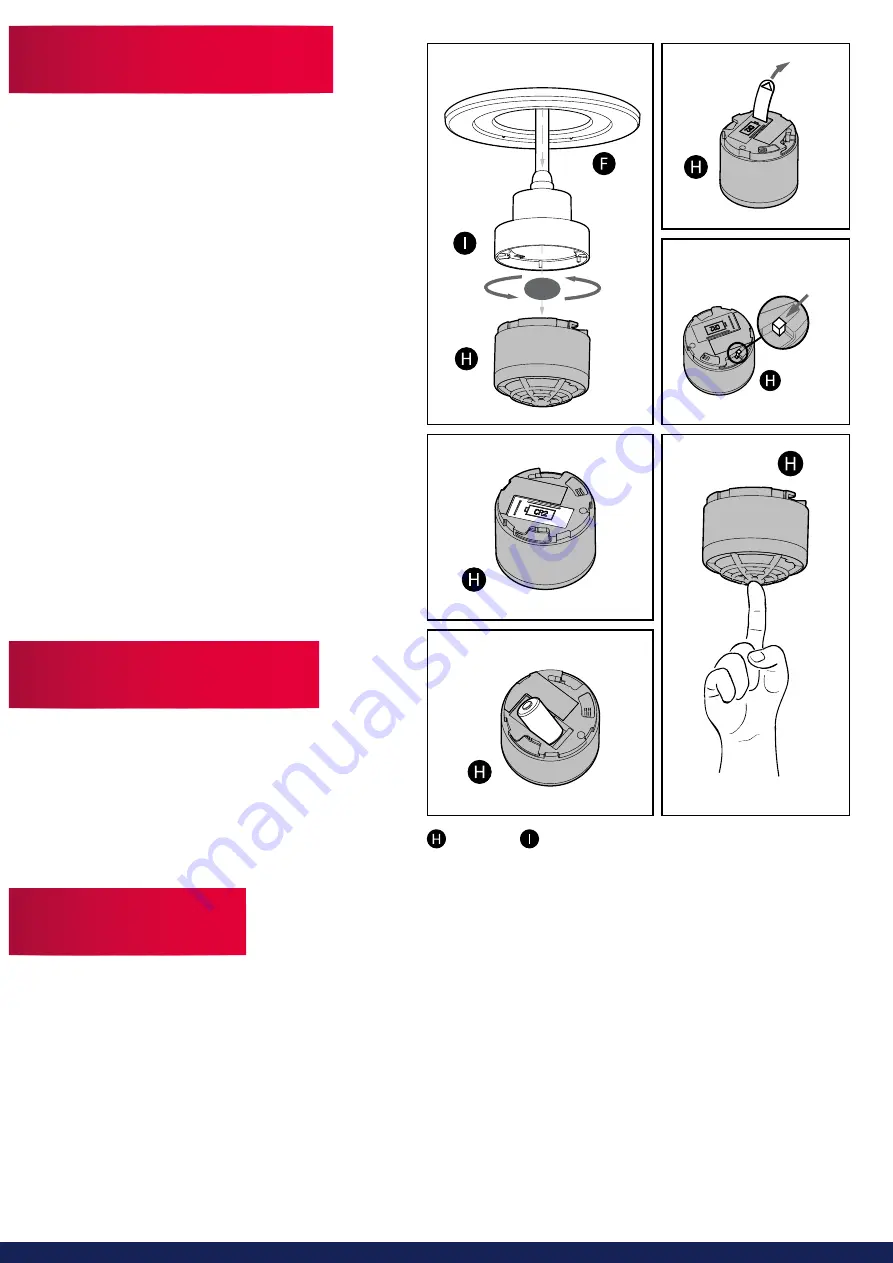
1) Pull down the heat alarm away from the luminaire so the
magnets are not connected anymore. (Diagram 5)
2) Twist the heat alarm anti clockwise to release the alarm
from the mains power.
3) Pull out the battery isolation strip in the battery
compartment as shown (Diagram 6)
Please note: RF connection is done with the device
powered with the battery only. You do not have to
connect the power supply. The product label must not be
removed as it contains important information regarding
the product.
4) All alarms to be connected in the house should be put
into ‘Learn Mode’ by sliding the switch on the back of the
alarm to the ‘Learn Mode’ position. (Diagram 7)
Please note: The learn switch placed on the back of
the alarm can only be in learn position when the alarm
is disassembled from the power supply unit. The learn
switch will automatically switch to normal position when
the alarm head is fitted to the power supply.
5) The red LED will light up to indicate that ‘Learn Mode’ has
been selected. Do not remove the battery during ‘Learn
Mode’ as this will interrupt the learn process.
6) Press and hold the test button on one alarm only, until
It beeps and the red LED flashes. This alarm will then
become the master and will start sending out a specific
house code to the other alarms. As the other alarms
receive the specific house code, their red LED will also
flash. When all alarms are flashing, they are connected
and can be switched out of ‘Learn Mode’ and installed
back within the luminaires.
1) Pull down the heat alarm so the magnets are not
connected to the luminaire. (Diagram 5)
2) Twist the heat alarm anti clockwise to release the alarm
from the mains power.
3) On the back of the alarm remove the cap over the battery
(Diagram 8)
4) Remove the battery and replace with a new battery
(Diagram 9)
Please note: You will not be able to install the heat alarm
without a battery being in the alarm and a CR2 battery is the only battery that can be used.
After installation, and at least once a month, test all of your alarms to ensure they are operating correctly and are within range of each
other (Diagram 10).
It is recommended to check visually every week if the LED flashes correctly (Every 48 seconds).
Press the test button on any alarm (This is on the front plate of the alarm) for at least 10 seconds. This will send out a test signal from
the alarm; all other connected alarms will receive the signal within a short time and the LED will flash every 8 seconds for two minutes.
Please note: Test function also transmits a weaker RF signal to ensure an optimal operation in normal conditions.
When the test signal is sent out, the alarms will respond in two ways:
1. A single beep every 8 seconds indicates that the alarms are connected and functioning.
2. Three short beeps every 8 seconds indicates a heat sensor fault. The alarm should be cleaned by running the vacuum (on a low
setting) around the heat alarm chamber and tested again.
If required this indication can be stopped early on each alarm by a short press of the test button.
If the problem continues please contact Lumi-Plugin.
5
6
Click!
Learn
Mode
Set / Test
10
7
Heat Alarm
Power Supply
8
9


