


2
NOTICE
Exercise caution as the reverse pliers may damage the
threads in valve chamber or spring retainer.
5. If the inlet spring retainer separates from the inlet seat, remove the spring and valve from
the valve chamber. Thread an M8 screw into the inlet seat and remove from valve chamber.
6. To separate valve assemblies use the same M8 screw and thread
into bottom of seat until screw contacts bottom of valve. Continue
threading in screw until spring retainer separates from seat.
7. Remove o-rings from both seats and valve plug.
Reassembly
NOTE: Reassembly can done by either using the pre-assembled stacked valve
assembly (see step 1) or can be done on a piece part basis (see step 2).
1. Press in new pre-assembled stacked valve assembly into valve
chamber until fully seated, then go to step 16.
2. If replacing by piece parts continue with step 3.
3. Examine spring retainers for internal wear or breaks in the structure and replace as needed.
4. Examine springs for fatigue or breaks and replace as needed.
5. Examine valves and seats for grooves, pitting or wear and replace as needed.
6. Examine seat and valve plug o-rings for cuts or wear and replace as needed.
NOTE: Inlet valve seat, valve seat o-ring and inlet spring retainer are different than
discharge valve seat, valve seat o-ring and discharge spring retainer.
7. Lubricate and install new o-ring onto outside diameter of discharge seat.
8. Place discharge seat on work surface with small diameter side down.
9. Place valve onto seat with concave side down, then spring on valve.
10. Install short spring retainer with deep stepped end over spring and snap onto seat.
11. Lubricate and install new o-ring onto outside diameter of small inlet seat.
12. Place inlet seat on work surface with o-ring side down.
13. Place valve onto seat with concave side down, then spring on valve.
14. Install tall spring retainer with deep stepped end over spring and snap onto seat.
15. Snap discharge valve assembly onto inlet valve assembly and then press
entire assembly into valve chamber until completely seated.
16. Lubricate and install new o-ring onto hex valve plug.
17. Thread in hex valve plug with pressure regulator by hand.
Torque to 310 in-lbs, 25.8 ft-lbs (35 Nm).
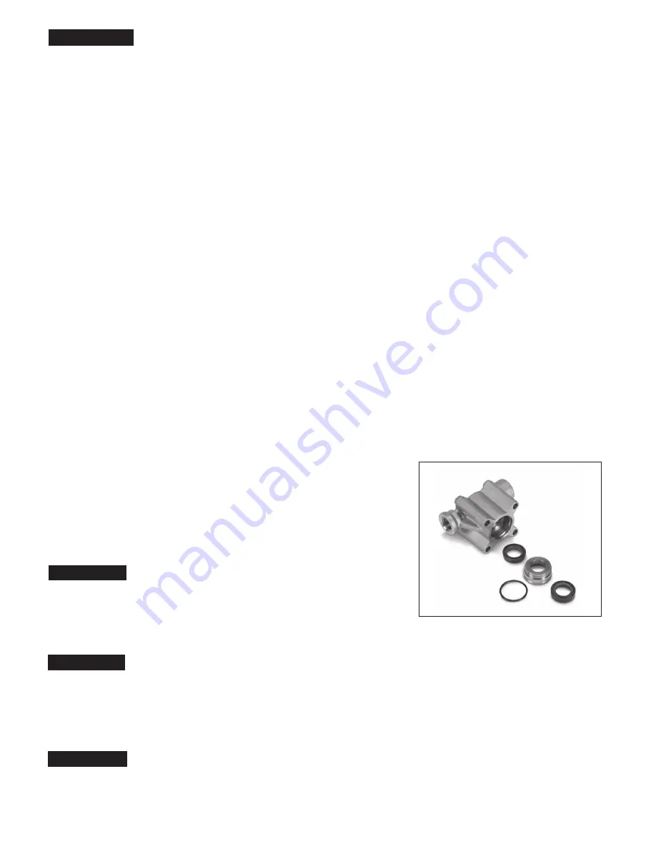
SERVICING THE SEAL
Disassembly
NOTE: All pump models require one (1) seal kit to repair pump.
1. Use a M5 allen wrench to remove the four (4) hex socket
head (HSH) screws from the manifold head.
2. Support the manifold head from the underside and pull
the manifold head away from the crankcase.
NOTICE
Keep the manifold head properly aligned with the ceramic plunger
when removing to avoid damage to the plunger.
3. Place manifold head on work surface with crankcase side up.
4. Remove seal retainer from plunger rod.
5. Use a screwdriver to pry out the Lo-Pressure seal from seal case.
NOTICE
Screwdriver may damage seal during removal.
6. Insert a reverse pliers into the second lip of the seal case and pull seal case from seal chamber.
NOTE: Do not insert reverse pliers into the first lip of the seal case because this
may damage the sealing surface area for the Lo-Pressure seal.
7. Carefully insert a small screwdriver under the o-ring and roll the o-ring off seal case.
NOTICE
Exercise caution as the screwdriver may score o-ring sealing surface.
8. Remove Hi-Pressure seal either by hand or with a reverse pliers from seal chamber.


