— 18 —
Removing the OPM unit
1
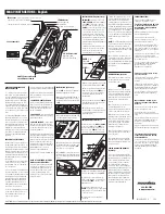
Remove three screws (S9) and then the OPM unit.
Note: There is a place where FPC and connectors are located closely with one another. Pay good attention
not to damage them.
Screws (S9)
FPC and connectors
Note: There is a wing for the encoder between the zoom and the focus.
Bending this wing may touch the reader part and cause noise.
Do not hold this wing part even though there is enough space for a finger to put in.
Do not hold this part by a
finger.
Содержание XJ-450
Страница 1: ...R XJ 450 MAR 2004 without price Ver 7 Feb 2006...
Страница 9: ...7 3 3 Basic structure...
Страница 51: ...49 131 112 113 116 120 123 124 133 135 137 127 129 130 131 131 117 118 134 111 128 136 119...
Страница 56: ...54 13 Schematic Diagrams Main PCB 1 7 PW BLOCK...
Страница 57: ...55 Main PCB 2 7 VGA INTERFACE...
Страница 58: ...56 Main PCB 3 7 VIDEO BLOCK...
Страница 59: ...57 Main PCB 4 7 MEMORY CONNECTOR BLOCK...
Страница 60: ...58 Main PCB 5 7 DMD INTERFACE...
Страница 61: ...59 Main PCB 6 7 SUB CPU BLOCK...
Страница 62: ...60 Main PCB 7 7 IP00C782 BLOCK...
Страница 63: ...61 Jack PCB PWB G790 C 3 Connector PCB PWB G790 C 7 Infrared PCB PWB G790 C 4...
Страница 64: ...62 Key PCB 1 2 PWB G790 C 5...
Страница 65: ...63 Key PCB 2 2 PWB G790 C 6...


