background image

– 1 –

SPECIFICATIONS

11 

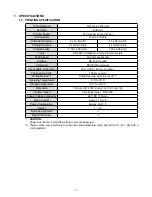
PRINTING SPECIFICATION

1111 

Printing Method

Direct Line Thermal

Dot Pitch

8 dot/mm

Printing Speed

210 mm per second (max.)

Printing Width

72 mm/576 dots

Character Structure

8 x 16 (font B)

12 x 24 (font A)

Printing Columns

64 columns/line

44 columns/line

Character Size

1.00 x 2.00 (mm)

1.50 x 3.00 (mm)

Fonts

US-ASCII, Katakana, international characters

Feed Speed

220 mm per second

Interface

RS-232C (serial)

Command

ESC/POS compliant

Paper Width & Diameter

80 mm (W) x 80 mm Dia. Max.

Thermal Head Life

100 km or more

Cutting Method *1

Partial cut (one point left uncut) *1

Operating Temperature

5 °C to 35 °C

Storage Temperature

-20 °C to 60 °C

Dimension

145 mm (W) x 193.2 mm (L) x 120.1 mm (H)

Transfer Speed

38.4 kbps (max.) : RS-232C

Supply Voltage In Standby

24 V DC / 100 mA

Mean Current

Approx. 1.3 A *2

Power Consumption

Approx. 40 W *2

Weight

1.1 kg

Barcode Alignment

Near End Sensor

*1: 

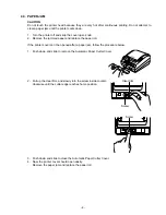
CAUTION:


Paper must be fed 3 mm after cutting to prevent paper jam.

*2:  These values vary according to environmental temperature when printed font A (12 × 24) with a 

rolling pattern.

Содержание UP-370

Страница 1: ...SERVICE MANUAL UP 370 MAY 2009 INDEX ...

Страница 2: ...NTERFACE SPECIFICATION 2 2 DISASSEMBLY 4 3 CIRCUITRY 7 3 1 POWER SUPPLY CIRCUIT 7 4 MAINTENANCE TROUBLESHOOTING 8 4 1 INSTALLING OR REPLACING PAPER ROLL 8 4 2 ADJUSTING THE PAPER NEAR END SENSOR 8 4 3 PAPER JAM 9 4 4 TROUBLESHOOTING 10 4 5 SELF TEST 11 5 THE DIP SWITCHES 12 5 1 Dip switch 1 setting 12 5 2 Dip switch 2 setting 12 5 3 For changing DIP switch setting 13 6 CIRCUIT DIAGRAMS 14 7 PARTS ...

Страница 3: ...and ESC POS compliant Paper Width Diameter 80 mm W x 80 mm Dia Max Thermal Head Life 100 km or more Cutting Method 1 Partial cut one point left uncut 1 Operating Temperature 5 C to 35 C Storage Temperature 20 C to 60 C Dimension 145 mm W x 193 2 mm L x 120 1 mm H Transfer Speed 38 4 kbps max RS 232C Supply Voltage In Standby 24 V DC 100 mA Mean Current Approx 1 3 A 2 Power Consumption Approx 40 W ...

Страница 4: ... finished It must not be NNNNNN adhesively attached or attached in another semi permanent manner INTERFACE SPECIFICATION 11111 RS 232C SPECIFICATION 1111111 Data Transmission Serial EIA RS 232C compliant Synchronization Asynchronous Handshaking DTR DSR or XON XOFF control Signal Levels MARK 3 to 15 V Logic 1 OFF SPACE 3 to 15 V Logic 0 ON Baud Rate 4800 9600 19200 38400 bps Data Word Length 8 bits...

Страница 5: ... Drawer kick out drive signal 1 3 Input Drawer open close signal 4 Output 24 V 5 Output Drawer kick out signal 2 6 Signal ground Two drawers can be used with a Y cable that meets the following specifications Pin 1 Frame ground Pin 2 Drawer kick out drive signal 1 Pin 3 Drawer open close signal Pin 4 24 V Pin 5 Drawer kick out signal 2 Pin 6 Signal ground Pin 6 Pin1 Pin2 Pin3 Pin4 Pin6 Pin1 Pin2 Pi...

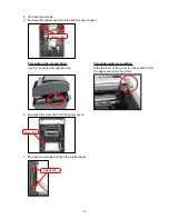
Страница 6: ...22 Remove four screws at the bottom of the printer unit 111 Remove five connectors CN1 CN2 CN3 CN5 CN6 and the FFC J1 222 Screws S11 CN3 CN2 J1 CN1 CN5 CN6 Remove three screws and then remove the main PCB 333 Screws S3 ...

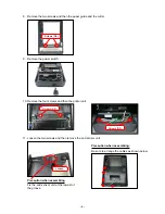
Страница 7: ...g Slide the lever of the cover to close and then fit the upper cover into the printer Remove two screws 444 Remove the upper cover while the printer cover is open 555 Screws S7 Remove two screws and then the control panel 777 Screws S4 Remove the screw and then the printer cover 666 Screw S9 ...

Страница 8: ...s and then the printer unit 1111 Remove the power switch 999 Screws S3 Screws S3 Loosen the two screws and then remove the end sensor unit 1111 Precaution when assembling Fix the end sensor unit at the lowest of the groove Precaution when assembling Be sure to arrange the cables as shown below Loosen ...

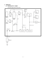
Страница 9: ...is a DC 24 V AC ADAPTOR CPU VCC3 ROM RAM U1 U2 U3 21 U13 U14 DRIVER DRIVER DC 24 V POWER SW U18 U19 U11 VP 24 V Q5 FET VP HVP VCC VCC VCC VCC VP AUTO CUTTER PRINTER MOTOR PRINTER HEAD BUFFER LATCH U7 LED DS1 VCC3 VCC3 VCC3 OTHER IC REGULATOR REGULATOR VCC 5 V VCC3 3 3 V ...

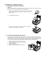
Страница 10: ...the excess paper on the cutter edge ADJUSTING THE PAPER NEAR END SENSOR 44444 A sensor detects when the paper roll is running out Due to variation in the width of paper roll cores it is difficult to measure the exact length of the paper left on the roll when the detector is triggered The factory setting is based on a paper roll core with an outside diameter of 18 mm and an inside diameter of 12 mm...

Страница 11: ...e paper roll 222 If the printer cover can t be opened after a paper jam follow the procedure below Push down and slide to remove the Automatic Paper Cutter Cover 111 Pull up the clear film and slowly turn the screw inside counter 222 clockwise until the cutter edge reaches home position Push down and slide to close the Automatic Paper Cutter Cover 333 Now the printer cover should open easily 444 R...

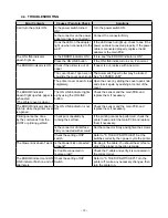
Страница 12: ... paper is exhausted The printer cover is close The ON LINE indicator lights up by using the ON LINE button Check the sensor and the main PCB and replace them if necessary The ERROR indicator doesn t light up while the printer cover is opened The ON LINE indicator is not ON Check the sensor and the main PCB and replace them if necessary Printing cannot be done by the commands from the HOST or print...

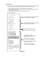
Страница 13: ...test starts The self test will end automatically and detach the self test print out 333 Self Print Japanese CG Cut Printing quality is confirmed 24 dot font ANK one byte characters Page 1 20 h FF h 24 dot font Chinese characters 30 h 21 h 90 characters total 16 dot font ANK one byte characters Page 1 20 h FF h 16 dot font Chinese characters 30 h 7B h 176 characters total The number changes accordi...

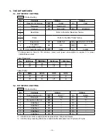
Страница 14: ...0 mm sec max and power consumption to approx 8 A max instantaneous value Table Baud rate No 4800 bps 9600 bps 19200 bps 38400 bps 4 off off on on 5 off on off on Table Parity No NON EVEN ODD NON 6 off off on on 7 off on off on DIP SWITCH 2 SETTING 55555 Default setting No Contents Status Status 1 Data reception error Off Print On Ignore 2 Bit length Off 8 bit On 7 bit 3 Reception buffer full Off 1...

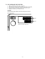
Страница 15: ... metal plate at the bottom of the printer 222 Change the status of DIP switch by using something with a point 333 Replace the metal cover and fasten the screw 444 CAUTION The new status becomes effective when the printer power is turned on DIP Switch Position ON ON 1 1 OFF DIP 1 DIP 2 ON OFF ON Remove the screw and metal cover ...

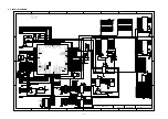
Страница 16: ...IV RTCCL 40 P34 TIAA10 TOAA10 TOAA1OFF INTP09 PPON 41 P35 TIAA11 TOAA11 RTC1HZ OCI 42 P36 TXDC3 SCL00 UDMARQ0 43 P37 RXDC3 SDA00 UDMAAK0 44 EVSS 45 EVDD 46 P50 TIAB01 KR0 TOAB01 RTP00 UDMARQ1 47 P51 TIAB02 KR1 TOAB02 RTP01 UDMAAK1 48 DDI 49 DDO 50 DCK 51 DMS 52 DRST 53 P90 KR6 TXDC1 SDA02 A0 54 P91 KR7 RXDC1 SCL02 A1 55 P92 TENC01 TIT01 TOT01 A2 56 P93 TECR0 TIT00 TOT00 A3 57 P94 TIAA31 TOAA31 TEN...

Страница 17: ... R67 0 R71 0 R69 0 R70 0 R68 0 R66 0 7 6 5 U12B uPC393G 2 1 2 3 4 5 6 7 8 9 10 11 12 13 14 15 16 17 18 19 20 21 22 23 24 25 26 27 28 J1 28FE BT VK N R5 470 C22 0 1uF 1 2 3 4 CN2 53047 0410 R35 10K R181 1 2 CN3 B2B EH C26 0 1uF R6 470 R40 10K R182 VCC3 VCC VP VCC3 VCC3 HVP VCC VCC3 VCC3 VCC3 VCC3 VCC3 VCC3 VP VCC3 HVP VCC VCC VP VCC3 VCC3 RMT0 HEADUP PEND RMT1 RMT2 RMT3 RMT4 RMT5 RTH HLAT HCLK HDAT...

Страница 18: ...35 0 1uF R72 0 R73 0 VCC3 VP VCC3 VCC3 VCC3 VCC VCC3 VP VCC VP VCC VCC3 VCC3 VP VCC3 DRW1 DRW2 DRWSENS ST0 ST1 ONLINE_SW RFEED BUZZER LDSR DSRRS T RES DRAW ER OP Pannel ONLINE ERRER POWE RSW 0251005 025101 5 CB 1 SS 2 SYNC 3 FB 4 ON OFF 5 GND 6 VIN 7 VSW 8 U18 LM2672MX 5 0 C73 0 01uF OUT 3 IN 2 GND 1 U19 SPX1117_3 3 VCC3 C36 0 1uF C37 0 1uF D5 MCL355 D6 MCL355 D7 EC31QS06 EC3 100uF 50V EC4 1000uF ...

Страница 19: ... VCC SA0 SA1 SA2 SA3 SA4 SA5 SA6 SD0 SD1 SD2 SD3 SD4 SD5 SD6 SD7 SD8 SD9 SD10 SD11 SD12 SD13 SD14 SD15 SA3 SA4 SA5 SD0 SD1 SD2 SD3 SD4 SD5 SD6 SD7 SD15 SD14 SD13 SD12 SD11 SD10 C235 0 47uF 16V EC200 10uF 16V C234 0 47uF 16V C233 0 47uF 16V C232 0 47uF 16V CS 1 SK 2 DI 3 DO 4 VCC 8 NC 7 NC 6 GND 5 U201 C225 VCC3 VCC18A 5 EEDIO 19 TPI 4 TPI 3 GND3A3 2 VCC3A3 1 SD9 33 EECK 20 SA1 49 GND 18 RSTn 17 EE...

Страница 20: ... column corespond to the same numbers in drawing 4 CASIO does not supply the spare parts without parts code 5 Remarks Q ty Quantity used per unit RANK A Essential B Stock recommended C Less recommended X No stock recommended PARTS LIST 777 PARTS LIST MODEL UP 370 CONTENTS EXPLODED VIEW 19 1 MAIN BOARD UNIT 20 2 CONTROL PANEL 20 3 I F PWB UNIT 20 4 POWER SW ASSY 20 5 NEAR END SENSOR UNIT 20 6 CASE ...

Страница 21: ...NTER To MAIN PWB CN1 To MAIN PWB CN2 To MAIN PWB CN6 To MAIN PWB CN5 1 2 S4 3 4 30 32 31 S3 S11 32 41 42 43 6 39 7 40 S13 S6 S6 S7 S3 8 38 10 11 12 13 17 19 S4 20 21 S5 S3 24 S2 26 S1 14 22 S9 S9 S9 S9 S9 25 23 29 27 33 34 28 16 S2 S3 S3 S3 S3 S3 18 35 36 37 15 9 5 S10 S10 S12 S8 21 ...

Страница 22: ...4791270LF 1 DD A 19 LEVER 03 45300870LF 1 20 10328158 F F C 00 62200555LF 1 AR C 21 ASSY HARNESS 03 47410550LF 2 22 SHEET PVC 03 13170200BLF 1 23 10328152 CASE TOP 03 24190898BLF 1 BB C 24 10328153 PAPER CUTTER 01 24301030LF 1 AE A 25 10328154 PAPER GUIDE 03 46001130CLF 1 AO C 26 SPRING 03 10400410BLF 1 27 10328155 KNOB 03 10602129LF 1 AC C 28 HOOK ARM 03 41502450CLF 1 29 LABEL CONTROL SW 00 31113...

Страница 23: ...0010LF 2 S3 SCREW 03 55191250LF 17 S4 SCREW 03 55190710LF 3 S5 SCREW 03 55101260BLF 2 S6 SCREW 03 55104020LF 4 S7 SCREW 03 55100440LF 2 S8 SCREW 03 55180045LF 2 S9 SCREW 03 55100420LF 14 S10 SCREW 03 55100121LF 2 S11 SCREW 03 55100430LF 4 S12 SCREW 2 S13 SCREW 03 55100150LF 1 10328160 ADAPTOR 02 22620150LF 1 DK A ...

Страница 24: ...CASIO COMPUTER CO LTD Overseas Service Division 6 2 Hon machi 1 Chome Shibuya ku Tokyo 151 8543 Japan ...

Отзывы: