background image

— 9 —

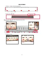
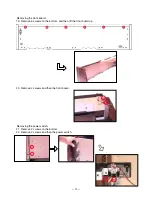
* Caution while assembling the key cover.

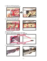
18. Remove 24 screws and then the KEY-BOARD ASSY.


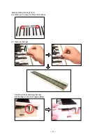
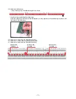
Removing the key board.

17. Remove 3 screws and then the CN-PANEL ASSY.

Содержание Privia PX-700

Страница 1: ...ELECTRONIC KEYBOARD PX 700 SEP 2005 PX 700 Ver 9 Jan 2010 INDEX...

Страница 2: ...CONTENTS Specifications 1 Block Diagram 2 Circuit Description 3 Printed Circuit Board 4 Disassembly 6 Diagnostic Program 14 Schematic Diagrams 16 Exploded View 20 Parts List 22...

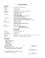
Страница 3: ...Hz 50 cents adjustable MIDI 16 multi timbre receive Input Output Headphones Stereo standard jacks 2 Output Impedance 170 Output Voltage 5 5V RMS MAX Power 12V DC MIDI OUT IN Pedal connector Speakers 1...

Страница 4: ...t IC1 MR27V6402G19RTN03D MA0 MA20 MD0 MD15 MA0 MA3 MD0 MD15 KEY CONTROLLER IC14 TC190C020AF 001 Keyboard Power Supply Circuit IC202 Q206 Q207 D206 D207 12V VA12 5V VD5 5V VA5 5V VI5 MA0 MA16 25 Speake...

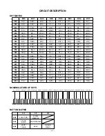
Страница 5: ...2 C2 2 D22 D2 2 E22 F22 F2 2 G22 G2 2 FI3 A21 A2 1 B21 C31 C3 1 D31 D3 1 E31 SI3 A22 A2 2 B22 C32 C3 2 D32 D3 2 E32 FI4 F31 F3 1 G31 G3 1 A31 A3 1 B31 C41 SI4 F32 F3 2 G32 G3 2 A32 A3 2 B32 C42 FI5 C4...

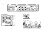
Страница 6: ...4 PRINTED CIRCUIT BOARDS MAIN PCB M404 MDA1 Bottom view Top view SUB PCB M404 PSA1...

Страница 7: ...5 CONSOLE PCB M406 CNA1 CONSOLE PCB M406 CNA2 CONSOLE PCB M406 CNA3 CONSOLE PCB M406 CNA4...

Страница 8: ...6 DISASSEMBLY 1 Remove 14 screws and then the lower panel 2 Remove the T BRD UNIT Removing the PCBs M404 MDA1 M406 CNA4 M404 PSA1 3 Remove 13 screws 3 Remove 4 screws T BRD UNIT...

Страница 9: ...7 5 Remove 11 screws 6 Remove the PCB case 7 Remove 3 connectors 8 Remove 4 screws 9 Remove the FPC and then the main PCB M404 MDA1 CN6 CN7 CN2...

Страница 10: ...connectors and 6 screws 13 Remove the sub PCB M404 PSA1 CN405 CN407 CN408 CN206 CN212 CN207 CN203 CN201 Removing the key cover 14 Remove 2 screws and then both sides of the stoppers 15 Remove 2 screws...

Страница 11: ...9 Caution while assembling the key cover 18 Remove 24 screws and then the KEY BOARD ASSY Removing the key board 17 Remove 3 screws and then the CN PANEL ASSY...

Страница 12: ...t board 19 Remove 6 screws on the bottom and then lift the front board up Removing the power switch 21 Remove 2 screws on the bottom 22 Remove 2 screws and then the power switch 20 Remove 2 screws and...

Страница 13: ...11 Removing the power switch 23 Remove 2 screws on the bottom 24 Remove 2 screws and then the PCB M406 CNA2 25 Remove the volume knob and 2 screws and then the PCB M406 CNA1...

Страница 14: ...12 Disassembling the key board 26 Remove 2 screws and then the bracket 27 Remove the keys Caution while assembling the keys Set the key as shown in figures below...

Страница 15: ...ength from others Caution while assembling the rubber keys Push the rubber keys with the tool like the tweezers so the projections of the rubber keys matches with the holes of the lower case 29 Remove...

Страница 16: ...UNCTION button to perform BUTTON check The confirmation chord C6 sounds 2 Press buttons in the order following NG tone sounds when an error is found in the buttons or when the buttons are pressed in a...

Страница 17: ...2sents 6 Remove the tuning meter from the jack PLAY LED lights 7 Press FUNTION button to finish the headphone check The confirmation chord C6 sounds 6 MIDI check If there is no MIDI cable this check c...

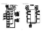
Страница 18: ...16 SCHEMATIC DIAGRAMS MAIN PCB M404 MDA1 NOTE The portions marked as UNUSED are not used on this model...

Страница 19: ...17 SUB PCB M404 PSA1 NOTE The portions marked as UNUSED are not used on this model...

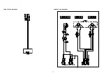
Страница 20: ...18 CONSOLE PCB M406 CNA1 CONSOLE PCB M406 CNA2...

Страница 21: ...19 CONSOLE PCB M406 CNA3 CONSOLE PCB M406 CNA4...

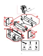
Страница 22: ...55 56 57 2 33 27 71 28 28 29 30 31 31 29 28 3 34 4 71 23 24 32 36 37 38 39 40 46 50 48 46 32 47 47 3 47 4 47 1 47 2 47 1 47 3 47 4 49 41 42 45 43 44 8 6 5 7 1 35 9 13 22 21 20 19 18 17 16 15 11 14 10...

Страница 23: ...4 Butterfly bolt x 2 Screw x 4 Screw cap Brown x 4 Screw x 2 Screw cap Black x 2 Clip x 2 53 74 54 74 40 36 37 38 39 67 51 52 72 73 52 3 52 2 52 1 51 3 51 1 51 2 55 59 66 68 65 64 63 61 57 56 58 58 62...

Страница 24: ...our spare parts department if you need these parts for refurbish 1 Prices and specifications are subject to change without prior notice 2 As for spare parts order and supply refer to the GUIDEBOOK for...

Страница 25: ...3200GS E1 A 1 AX X Q1 22592764 TRANSISTOR 2SB1188T100Q 1 AB X Q4 22530715 TRANSISTOR 2SD1664T100Q 1 AA X Q2 10202670 TRANSISTOR KTA2014 GR RTK P 1 AA X Q3 10207675 TRANSISTOR KTC4075 GR RTK P 1 AA X X...

Страница 26: ...MMER ASSY B4 TK RJM506042 001 9 AE C N 23 10204304 CHASSIS KEY RJM505515 001V01 1 BX C N 24 10213920 KEY UNIT TK RJM506362 001 1 EC B MAIN CASE UNIT N 25 10213944 BOARD ASSY TOP TK RJM505995 001 1 CI...

Страница 27: ...52 10213940 BOARD ASSY RIGHT TK RJM506116 001 1 CM C N 52 1 10195926 BOLT MU 0386353 1 AB C N 52 2 10214311 BRACKET ST RJM505788 002V01 1 AM C N 52 3 10195925 CROSS NUT MU 0370163 1 AD C N 53 10213951...

Страница 28: ...ts Code Parts Name Specification QTY Price Code R Remarks ACCESSORY 10128659 AC ADAPTOR AD 12UL TC2 D 1 CE C 120V 10168517 AC ADAPTOR AD 12FL TC3 D 1 CD C 230V N 10213941 STAND MUSIC TK RJM506318 001...

Страница 29: ...Correction of the PARTS LIST P25 Ver 4 Oct 2007 Correction of the EXPLODED VIEW P20 21 Correction of the PARTS LIST P25 Ver 5 Dec 2007 Correction of the DIAGNOSTIC PROGRAM P14 Correction of the EXPLOD...

Отзывы: