


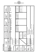

(3) Real-time Sampling Channel (Use CH)
•
1
(CH1) ........ Channel 1
•
2
(CH2) ........ Channel 2
•
3
(CH3) ........ Channel 3
•
4
(SONIC) .... Sonic channel
• Note that the above options appear only when real-time sampling is turned on (by
pressing
1
(YES) for the Real-Time item).
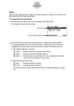
(4) Filter Settings (Filter)
•
1
(None) ....... No setting
•
2
(S-G) ......... S-G Smoothing
b
(5-p): 5-point
c
(9-p): 9-point
d
(17-p): 17-point
e
(25-p): 25-point
•
3
(MED) ....... Median Filter
b
(3-p): 3-point
c
(5-p): 5-point
• Note that the above options appear only when real-time sampling is turned off (by
pressing
2
(NO) for the Real-Time item).
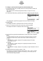
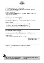
3. After all the settings are the way you want, press
w
to return to the Advanced Setup
menu.
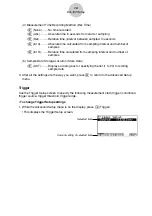
u
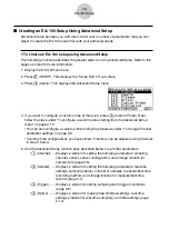
To configure a custom probe
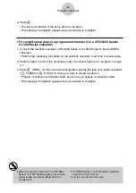
You can use the procedures in this section to configure a custom probe*
1
for use with the
EA-100.
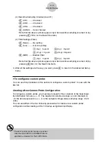
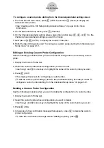
Creating a New Custom Probe Configuration
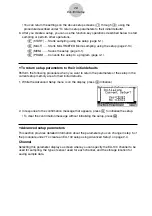
To configure a custom probe, you must input values for the constants of the fixed linear
transformation formula (
ax
+
b
). The required constants are slope (
a
) and intercept (
b
).
x
in the above expression (
ax
+
b
) is the sampled voltage value (sampling range: 0 to 5
volts).
You can use either of the two following procedures to create a new custom probe
configuration while creating an EA-100 setup using Advanced Setup.
2-11
EA-100 Setup
*
1
The term “custom probe” means any sensor
other than the CASIO or VERNIER sensors
specified as standard for the E-CON Mode.