background image

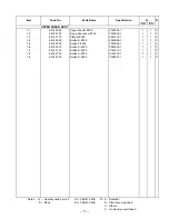
Item

Code No.

Parts Name

Specification

Q

R

AA

EA

COMPONENT

1

6418 3570

Upper case B ass'y

C140399*1

1

1

B

2

6561 7250

Tape S-Z305

C441820-1

1

1

B

3

6418 3760

Inner case B-Z305

C140377-1

1

1

B

4

6418 4310

Z305-M ass'y

C240786*1

1

1

B

5

6418 3550

Z305-1 PCB ass'y

C140397*1

1

A

5

6670 1334

Z305-1 PCB ass'y

C140397*2

1

A

6

6670 1378

Lock switch ass'y

C441778*1

1

1

B

7

6418 3810

Filter Z305

C240732-1

1

1

B

8

6418 3820

Connector cover Z305

C240733-1

1

1

A

9

6418 7130

Screw A-Z305

A311191-7

3

3

B

10

6418 3580

Lower case B ass'y

C140400*1

1

1

B

11

6334 6470

Screw A-G368

A33953-15

3

3

B

12

6339 1750

Screw A-G912

A33953-33

2

2

B

13

6418 4160

Label C-Z305

C441478-1

1

1

B

14

6418 3870

Battery cover B-Z305

C340921-1

1

1

A

15

6418 4030

Screw Z305

C413301-4

1

1

B

16

6418 3851

ROM case Z305

C240743A-1

1

1

A

17

6385 8740

Screw A-V331

C41077-7

1

1

B

19

6561 7240

Label D-Z305

C441787-1

1

1

B

20

6561 7850

Pen sub ass'y

C341364*1

1

1

A

21

6561 7200

Label G-Z305

C441821-1

1

1

B

22

6390 0432

Cap V332

A310765B-1

1

1

A

23

6540 5580

Dummy card L970AA

C211156-1

1

1

B

24

6418 3660

Battery case ass'y

C341040*1

1

1

A

25

6561 7220

Label F-Z305

C441819-1

1

1

B

27

6561 8390

Serial seal Z305A

C441759-1

1

B

27

6561 8400

Serial seal Z305E

C441759-2

1

B

28

6561 8200

Tape U-Z305

C441851-1

1

1

B

29

6418 4110

Label A-Z305

C441468-1

1

1

B

   Notes:     Q –  Quantity used per unit

R – A : Essential

 R –  Rank

B : Stock recommended

C : Others

X : No stock recommended

AA :
EA :

CASIO 2 MB
CASIO 4 MB

— 75 —

Содержание Cassiopeia A-10

Страница 1: ...Handheld Personal Computer A 10 A 11 ZX 305 314 R MAR 1997 without price A 11 ...

Страница 2: ...1 TO A DESKTOP COMPUTER 12 CONNECTING TO EXTERNAL EQUIPMENT 12 REPLACING MEMORY SLOT 13 MEMORY BACKUP RESTORE 15 Backup 15 Restore 17 BLOCK DIAGRAM 19 DEVICE FEATURES 20 LSI IC DATA 22 MB87A908A SYSTEM LSI U3 22 MBCG25942 5110 GATE ARRAY U4 25 HD6417096 SH3 CPU U1 27 MC34119 U5 29 MAX3241CAI U6 29 UPD42S16165LG5 30 RN5VD18CA U9 30 XC61A or RH5V Series U12 17 U32 31 TFDS3000TR3 IrDA Module U18 31 M...

Страница 3: ...5 1 PCB 2 2 62 SCHEMATIC DIAGRAMS 63 Z305 1 PCB 1 7 CPU SYSTEM LSI 63 Z305 1 PCB 2 7 POMCIA CARD I F 64 Z305 1 PCB 3 7 MEMORY 65 Z305 1 PCB 4 7 AUDIO TOUCH PANEL 66 Z305 1 PCB 5 7 RS232C IrDA 3 PIN 67 Z305 1 PCB 6 7 POWER SUPPLY 68 Z305 1 PCB 7 7 DETECTOR 69 Z305 S1 PCB EL 70 Z305 LD PCB LCD POWER 71 Z305 KY PCB KEYBOARD 72 Z305 MMR PCB MEMORY SLOT 73 EXPLODED VIEW AND PARTS LIST 74 COMPONENT 74 U...

Страница 4: ...f one minute input and 10 minutes input standby Main Battery life is shortened considerably by use of a modem card or any other high power consumption PC card Back up 5 year when main battery is replaced immediately after appearance of low battery message 1 month when unit is left without a main battery Operating Temperature 0 C to 40 C 32 F to 104 F Dimensions excluding projections Unfolded 15 0H...

Страница 5: ...r Low battery message detector for alkaline batteries VDET2 1 6 0 04 V or under Foced power off detector for alkaline batteries VDET1R 2 3 0 03 V or under Low battery message detector for rechargeable battery VDET2R 1 9 0 02 V or under Foced power off detector for rechargeable battery VDETS 2 7 0 03 V or under Low battery message detector for back up battery IrDA A L A 10 11 A 10 11 ...

Страница 6: ...kaline Batteries two OPTIONS UT S11 This set includes an AC adapter charger rechargeable battery pack and CR A10 Slip the A 10 A 11 into the CR A10 for quick and easy exchange of data with a desktop computer Also the CR A10 makes it possible to use the RS 232C cable and the Charger at the same time AC S10 This set includes an AC Adapter and CR M10 The CR M10 makes it possible to use the RS 232C ca...

Страница 7: ... 4 Data Communication Cable SB 62 This cable is used to connect a digital camera or other external equipment to the A 10 A 11 CR A10 CR M10 CH 50150A NH 10A Charger Rechargeable Battery Pack ...

Страница 8: ...light on and off The Backlight turns off auto matically if you do not perform any key or stylus input operation for some time Data communication jack For connection of a digital cam era or other external equip ment Card slot PC card Stylus For performing operations on the touch screen Take care to avoid damaging or losing the stylus Panel latch Press to open the panels Main battery holder Holds ma...

Страница 9: ...ones and other sounds Notification Button Turns off the flashing light and stops the alarm RS 232C Power connector For connection of an RS 232C cable docking station mini dock or battery pack charger Infrared port Contrast dial Rotate to adjust diplay contrast Rotate upwards to make the display lighter or downwards to make it darker ...

Страница 10: ...ommunication port One CD ROM drive 3 5 high density disks provided on request VGA or higher resolution graphics card SVGA 256 color recommended Microsoft Mouse or compatible pointing device Options Audio card speakers for sound SETTING UP Use the following procedure to set up the A 10 A 11 before using it for the first time 1 Load batteries Load the two alkaline batteries that come with the A 10 A...

Страница 11: ...upply Never use any other types of batteries with the A 10 A 11 Be sure to keep track of the battery life of both the main batteries and the back up battery If the batteries being used for both power supplies are low at the same time data stored in memory can be corrupted or lost entirely Replacing the Main Batteries 1 Make sure the A 10 A 11 is turned off If the A 10 A 11 is on press the power sw...

Страница 12: ...main battery holder into the A 10 A 11 until the holder is fully seated 1 2 6 Slide the release both buttons of the main battery holder towards NORMAL OPERATION to lock the main battery holder release 7 If you are loading batteries into the A 10 A 11 for the first time after purchasing it pull the insulating tape out from under the back up battery compartment cover according to the following order...

Страница 13: ...ng a rechargeable battery pack that is available as an option Charging of the optional battery pack is performed using an optional charger 4 Remove the old battery 5 Wipe the surfaces of the new battery with a soft cloth and then load it into the back up battery compart ment with the side facing up so you can see it 6 Replace the back up battery compartment cover and secure it in place with its sc...

Страница 14: ...ory Reset Performing the reset operation after memory data has been corrupted clears memory contents and set tings and causes the welcome wizard screen to appear Set up the A 10 A 11 in accordance with the on screen guidance To reset the A 10 A 11 1 Press the power switch to turn on the A 10 A 11 2 Use the stylus to press the reset button This causes the A 10 A 11 to turn off Important Always use ...

Страница 15: ...TING TO EXTERNAL EQUIPMENT You can connect the A 10 A 11 to a digital camera or other external equipment and exchange data Requirements Optional data communication cable SB 62 To connect to external equipment complete the following steps 1 Turn off the A 10 A 11 and the external equipment 2 Connect the data communication cable to the A 10 A 11 s data communication jack and the external equipment 2...

Страница 16: ...emory slot remaining batteries makes the electrical parts inside A 10 A 11 be defective 1 Make sure the A 10 A 11 is turned off 2 Remove the main batteries according to the chapter REPLACING THE BATTERIES 3 Remove the back up batteries according to the chapter REPLACING THE BATTERIES 4 Remove a screw and then remove the memory slot cover 5 Put the slot guide to outside the memory slot goes up Then...

Страница 17: ...older is fully seated And slide the release both buttons of the main battery holder towards NORMAL OPERATION to lock the main battery holder release 8 Press ON button and confirm the Welcome wizard appears 9 Press OFF button 10 Load the backup battery and replace the backup battery compartment cover and secure it in place with its screw ...

Страница 18: ...r Notes 1 Backup program of HPC Explorer back up only files and databases Setup data including Owner World Clock and so on can not be backed up to PC 2 Use AC adaptor when making backup copy and restoring Backup 1 Connect user s A 10 A 11 to your PC with RS 232C cable 2 Start HPC Explorer on your PC 3 HPC Explorer detects A 10 A 11 is connected automatically 4 PC shows the following dialog and cli...

Страница 19: ... 16 6 Click Full back up all files and Back Up Now 7 Confirm the file name of bakup copy and then click OK Backup starts ...

Страница 20: ... then Welcome wizard appears 2 Execute touch panel calibration and then skip other setups after calibration 3 Connect repaired A 10 A 11 to your PC with RS 232C cable 4 Start HPC Explorer on your PC 5 Click Restore and confirm the file name backuped Then click OK 6 Click Restore ...

Страница 21: ... 18 7 Restoring starts 8 Click OK ...

Страница 22: ...A U3 L C D E L Voltage Generator LA5312 U601 Contrast Dial LCD unit EL Driver HV803 IC801 Touch Panel Keyboard Audio Amp MC34119 U5 SP Notification LED Mini Jack IrDA IrDA Transceiver RS232C Transceiver TFDS3000 MAX3241 U6 U18 RS232C Connector Power Supply Circuit ACL Voltage Detector Recharger 3 3 V 5 V 24 0 V AAX2 Alkaline or NiMH CR2032 BLOCK DIAGRAM A 10 2 Mbyte A 11 4 Mbyte ...

Страница 23: ...System LSI MB87A908A U3 LCD Controller System Controller DRAM Access Controller Interrupt Controller Key Controller Audio Controller DMA Controller Touch Panel Controller Infra Red Controller RS232C I F Controller IrDA I F Controller 3 pin I F Controller LED Controller Gate Array MBCG25942 5110 U4 PCMCIA Controller LCD 4 gray levels 480 240 landscape 0 24 mm pitch LCD Driver 2 120 ch common driver...

Страница 24: ...cation Button Independent switch It wakes CPU up LCD Contrast Rotary switch Keyboard 56 keys and independent Ctrl Alt Right Shift Left Shift and Windows ON key is an independent switch Cradle Detector Detects whether system is in the cradle or not ACL Automatic hard reset for first time Power ON Reset occurs in case of ACL Battery Cover Detector Detects both open and closed Battery Detector Detect...

Страница 25: ...ROMB O Output enable ROM 30 FlSHRTB O Reset signal for Flash 31 PRESETB O Reset signal GA 33 CASLHB I CASLH signal to CPU CPU 34 CASLLB I O CASLL OE signal from CPU CPU 35 RASB I O RAS CE signal for CPU CPU 36 RDB I Up Read signal from CPU CPU 37 WRHB I O Up WE1 signal from CPU CPU 38 WRLB I O Up WE0 signal from CPU CPU 39 RDWRB I O Up RD WRB signal from CPU CPU 40 CS0B I Up CS0 signal from CPU RO...

Страница 26: ...n signal Keyboard 95 KBOUT5 O Key common signal Keyboard 96 KBOUT4 O Key common signal Keyboard 97 KBOUT3 O Key common signal Keyboard 98 KBOUT2 O Key common signal Keyboard 99 KBOUT1 O Key common signal Keyboard 101 XCKOUT I O Oscillator output Y3 102 XCKIN I Oscillator inut Y3 103 BATDTCT I Alkaline NiMH detecting port SW3 104 KBOUT0 O Key common signal Keyboard 105 KBDIN0 I Up Key segment signa...

Страница 27: ...Clock for LCD LCD 148 M O Alternating signal for LCD LCD 149 DISPOFFB O LCD off signal LCD 150 DU0 O Data for LCD LCD 151 DU1 O Data for LCD LCD 152 DU2 O Data for LCD LCD 153 DU3 O Data for LCD LCD 155 IRRXD I Infrared input IrDA 156 PIRB O Voltage V5IRDA 3 V control Q16 Power 157 IRTXD O Infrared output IrDA 158 MDCD I RS232C control RS232C 159 MDTR O RS232C control RS232C 160 RXDSH I O RXD1 sig...

Страница 28: ... 5 V Address Card 29 BVD1 I 5 V Battery Detector Card 31 CD2B I 5 V Card detect Card 32 V5D8 I O 5 V Data Card 33 V5D1 I O 5 V Data Card 34 V5D9 I O 5 V Data Card 35 V5D2 I O 5 V Data Card 36 V5D10 I O 5 V Data Card 38 MDCD O 3 V Port 39 D15 I O 3 V Data CPU 40 D14 I O 3 V Data CPU 41 D13 I O 3 V Data CPU 42 D12 I O 3 V Data CPU 43 D11 I O 3 V Data CPU 44 D10 I O 3 V Data CPU 46 V5WAITB I 5 V Wait...

Страница 29: ...3 V Address CPU 104 A4 I 3 V Address CPU 105 A3 I 3 V Address CPU 106 A2 I 3 V Address CPU 107 A1 I 3 V Address CPU 108 A0 I Down 3 V Address CPU 110 SIFENB O 3 V 9 pin RXD1 control RS232C 111 SIFSHUTB O 3 V RXD1 signal for CPU CPU 112 RXD3 I 5 V 3 pin RXD signal Serial 113 TXD3B O 5 V 3 pin TXD signal Serial 114 V5A19 O 5 V Address Card 115 V5A14 O 5 V Address Card 116 V5A18 O 5 V Address Card 11...

Страница 30: ... Data bus 26 D8 I O Data bus 27 D7 I O Data bus 28 D6 I O Data bus 29 D5 I O Data bus 32 D4 I O Data bus 33 D3 I O Data bus 34 D2 I O Data bus 35 D1 I O Data bus 36 D0 I O Data bus 37 A0 I O Address bus 38 A1 I O Address bus 39 A2 I O Address bus 40 A3 I O Address bus 43 A4 I O Address bus 44 A5 I O Address bus 45 A6 I O Address bus 46 A7 I O Address bus 47 A8 I O Address bus 48 A9 I O Address bus...

Страница 31: ... O Read pulse SYSTEM LSI GA 108 CS6B CE1B O Chip select 6 signal GA 109 CS5B O Not used 110 CS4B O Chip select 4 signal SYSTEM LSI GA 111 CS3B O Not used 112 CS2B O Not used 113 CS1B O Not used 114 CS0B O Chip select 0 signal SYSTEM LSI M slot 117 ICIOWRB O Write signal for PCMCIA I O GA 118 ICIORDB O Read signal for PCMCIA I O GA 119 CAS2HB O D15 D8 select signals for RAM on Memory slot 120 CAS2L...

Страница 32: ...3241 MAX3241 C1 C1 C2 C2 T1IN T2IN T3IN R1OUTB R2OUTB R1OUT R2OUT R3OUT R4OUT R5OUT EN T1OUT V V T2OUT T3OUT R1IN R2IN R3IN R4IN R5IN SHDN 5k 5k 5k 5k 5k 25 GND 28 0 1 µf VCC 3 V to 5 5 V C1 VCC C2 C3 C4 LOGIC INPUTS RS 232 OUTPUTS RS 232 INPUTS LOGIC OUTPUTS 26 27 3 24 1 2 14 13 12 9 10 11 21 20 19 18 17 16 15 23 4 5 6 7 8 22 MC34119 U5 MAX3241CAI U6 Top View 1 2 3 4 CD FC2 FC1 Vin VO2 Gnd VCC VO...

Страница 33: ...Outputs RAS Row Address Strobe UCAS Column Address Strobe upper LCAS Column Address Strobe lower WE Write enable OE Output enable VCC Power Supply GND Ground NC No Connection 1 2 3 5 4 OUT Output H Detected VDD Voltage source GND Ground NC No connection CD Connect to capacitor for delay ...

Страница 34: ...OUT FB SHDN 8 7 6 5 1 2 3 4 1 2 3 VOUT VIN VSS VIN VSS Vref VOUT XC61A or RH5V Series U12 17 U32 TFDS3000TR3 IrDA Module U18 MAX608 U20 U22 Pin description 1 IRED Cathode 2 Rxd Output 3 Vcc Supply Voltage 4 Ground 5 NC 6 SD Shut down 7 Txd Input 8 IRED Anode ...

Страница 35: ...utput buffer 1 2 3 5 GND 1 2 3 5 4 VDD EXT VOUT NC Vref RN5RY Series U23 LA5312 Boot 1 2 3 4 5 6 7 8 9 10 20 19 18 17 16 15 14 13 12 11 R X3 R X2 R X4 V3 V IN3 NC V4 NC V EE NC V IN2 R X1 V2 NC V CC NC V1 STR V REF NC VIN2 RX1 RX2 RX3 RX4 VIN3 R R R R R 2R 4R 3R STR VREF VCC VEE V1 V2 V3 V4 RN5RG Series U26 LA5312V U601 ...

Страница 36: ... 33 VDD VDD RSW OSC CS LX REL osc VA VB GND RSW OSC GND Switch Osc Disable _ Vref REL OSC Output Osc CS LX VA VB C Q Q Q Q 1 2 3 4 8 7 6 5 HV803 IC801 EMI FILTER ARRAY UPD23C32000LGY ...

Страница 37: ...econdary Detector V5MAIN To Secondary Detector V3MAIN Lithium To Detector RBATMAIN Primary Circuit The voltage from both batteries alkaline and NiMH supplies to V5 and V3 circuits through the fuse when the battery is loaded The VBAT2 and RBATCHG are for the reference voltage for Primary detectors VBAT2 is for alkaline batteries detector RBATCHG is for NiMH detector RBATMAIN is for AC adaptor detec...

Страница 38: ...D To PCMCIA 5 V Circuit DC DC converter MAX608ESA U20 generates 5 11 V and it makes up 5 V system V5MAIN The reference voltage for the detector V5SYS 5 V source for U4 and 3 pin jack P5V Controls ON OFF of V5SYS From pin 170 of SYSTEM LSI V5CARD 5 V source for PCMCIA Card PCRD Controls ON OFF of V5CARD From pin 166 of SYSTEM LSI BATDTCT It distinguishes alkaline and NiMH to change the load accordi...

Страница 39: ...stem V3MAIN The reference voltage for the detector V3SYS 3 3 V source for U1 U3 U4 U6 D601 D602 Q3 Q7 V3RAM 3 3 V source for DRAM U7 and U8 V3ROM 3 3 V source for ROM U301 ONSTATUSB Controls ON OFF of V3ROM From pin 90 of SYSTEM LSI V3IRDA 3 3 V source for IrDA Transceiver TFDS3000 U18 PIRB Controls ON OFF of V3IRDA From pin 156 of SYSTEM LSI VSUB 3 V source for detecting memory backup battery V3A...

Страница 40: ...LA5312V LCD D D LCD D601 602 LED Q3 Q7 Touch Panel U7 U8 UPD42S16160 D RAM U6 MAX3241 RS232 C U5 MC34119 Audio IC U18 TFDS3000 IRIC Memory Slot V3SYS V3ROM V3RAM V3AUD V5SYS V5CARD V25LCD V3IRDA 25 V Circuit DC DC converter RN5RY202 U23 generates 25 V and it makes up 25 V system for LCD V25LCD 25 V source for LCD VOL Connect to Contrast Dial on Z305 LD PCB PLCDB Controls ON OFF of V25LCD From pin ...

Страница 41: ...tector V3SYS VBAT2 VDET1RB L Low battery message VDET2R H Forced power off VDET1B L Low battery message VDET2 H Forced power off U17 2 3V U16 1 9V U12 2 0V U13 1 6V SECONDARY DETECTOR VDET3B L Forced power off V5MAIN V3MAIN Alkalin NiMH Detector U14 3 4V Alkalin NiMH Detector U32 4 5V OR circuit Tr BACKUP BATTERY DETECTOR VSUB VDETS H Low battery message U15 2 7V AC ADAPTOR DETECTOR ACDTCTB L Adap...

Страница 42: ...Holder Release switch is on NORMAL OPERATION side START Load main batteries Remove Main and Backup batteries Press ON Display appear Press RESET button and then ON Adjust Contrast Dial Replace batteries with new one Display appear Display appear Display appear Repair needed To Diagnostic YES YES YES YES NO NO NO NO ...

Страница 43: ...hen release Ctrl CapsShift and ON Main Menu 0 AUTO MODE 1 DISPLAY 2 TOUCH PANEL 3 MEMORY 4 SERIAL 5 POWER CONTROL 6 AUDIO 7 Others CPROG Rev1 00 Main Battery Check 7 Others 1 Switch 2 PCMCIA implement 3 PCMCIA RAM card 4 PCMCIA WAIT 5 Keyboard RANDOM 6 Keyboard SERIAL 1 7 Keyboard SERIAL 2 8 EL 1 VDET1 OFF VDET2 OFF VDET1R OFF VDET2R indefinite VDET3 OFF VDETS ON Recharge OFF CHKPRG OFF AC Adapter...

Страница 44: ...display SPACE Insert RS JIG 232C to RS 232C connector and RS JIG 3PIN to data communication jack Serial Main Menu 0 AUTO MODE 1 DISPLAY 2 TOUCH PANEL 3 MEMORY 4 SERIAL 5 POWER CONTROL 6 AUDIO 7 Others 0 RESULT RS232C OK PCMCIA NG 3 PIN OK RAM OK 2M bytes or 4M byte Make sure display shows OK without PCMCIA Remove RS JIG 232C and RS JIG 3PIN Step Operation Display Note ...

Страница 45: ...eck sum value for 1 bit high and 1 bit Low of ROM ENTER 4 ROM CHECK SUM base addr sum value SUM 1 A0000000 817F SUM 2 A0200000 3C33 This mode displays the check sum value It takes 12 sec ENTER ENTER 7 Others 1 Switch 2 PCMCIA implement 3 PCMCIA card 4 PCMCIA WAIT 5 Keyboard RANDOM 6 Keyboard SERIAL 1 7 Keyboard SERIAL 2 8 EL Switches Make sure the display shows OK PCMCIA ENTER 7 Insert RAM card in...

Страница 46: ...ard Lock switch to LOCK CardLock CLOSED Slide Battery Replacement switch to REPLACE Cover OPEN Slide Battery Replace ment switch to NORMAL Cover CLOSED Plug in AC adapter AC Adapter USED Replace Rechargeable Battery Recharge ON Replace Alkaline batter ies Recharge OFF Plug out AC adapter AC Adapter NOT USED VDET1 OFF VDET2 OFF VDET1R OFF VDET2R indefinite VDET3 OFF VDETS ON Recharge OFF CHKPRG OFF...

Страница 47: ...ouch panel A cross is indicated on the LCD If a next cross does not appear when you tap the center of a cross it is NG When you tap the fourth cross Touch Panel menu appears Touch Panel 1 Calibration 2 Case 3 Points 4 Cross 2 Case Case OK Make sure the display shows OK ENTER 3 1 Tap center of 1 2 Tap center of 2 3 Tap center of 3 4 Tap center of 4 5 Tap center of 5 Standard Coordinates of point ta...

Страница 48: ... ENTER ENTER 6 Audio Audio 1 0 5 kHz 2 1 kHz 3 2 kHz This mode makes tone of sine wave sound Hear each tone and check it To cancel the tone press ENTER ENTER Main Menu 0 AUTO MODE 1 DISPLAY 2 TOUCH PANEL 3 MEMORY 4 SERIAL 5 POWER CONTROL 6 AUDIO 7 Others Step Operation Display Note ...

Страница 49: ... Baudrate 4 Receive data MIN Baudrate 1 Infrared SEND RECEIVE 1 Send data MAX Baudrate 2 Receive data MAX Baudrate 3 Send data MIN Baudrate 4 Receive data MIN Baudrate SEND MODE Infrared SEND RECEIVE 1 Send data MAX Baudrate 2 Receive data MAX Baudrate 3 Send data MIN Baudrate 4 Receive data MIN Baudrate 2 Infrared SEND RECEIVE 1 Send data MAX Baudrate 2 Receive data MAX Baudrate 3 Send data MIN B...

Страница 50: ...n 1 second ERROR mes sage is indicated in transmission beginning and transmission closing it is nor mal Infrared SEND RECEIVE 1 Send data MAX Baudrate 2 Receive data MAX Baudrate 3 Send data MIN Baudrate 4 Receive data MIN Baudrate HHHHHHHHHHHHHHHHH HHHHHHH Make sure H display stops ENTER ENTER Infrared SEND RECEIVE 1 Send data MAX Baudrate 2 Receive data MAX Baudrate 3 Send data MIN Baudrate 4 Re...

Страница 51: ...agnostic pro gram Main Menu 0 AUTO MODE 1 DISPLAY 2 TOUCH PANEL 3 MEMORY 4 SERIAL 5 POWER CONTROL 6 AUDIO 7 Others To boot the diagnostic re fer to page 40 Power Control 1 40MHz 2 standby 3 sleep 5 Power Control menu is for current consumption check 1 Power Control 1 40MHz 2 standby 3 sleep Currently CPU clock is 40MHz Main Bat tery at ON Current consumption at ON Measure the current Ib 210 mA or ...

Страница 52: ...s fig ure 1 Turn the power off 2 Supply the voltage to backup battery termi nals as figure right 3 Remove main batter ies 4 Measure the current Vs 3 0 0 05 V No display Current consumption of backup battery Measure the current Is 150 µA or under 2M byte Is 250 µA or under 4M byte Backup battery Step Operation Display Wiring Note Backup battery terminal Vs A V A 10 A 11 Is ...

Страница 53: ...ge that VDET2 becomes ON VDET2 1 6 0 04 V VDET1 VDET2 Voltage Detectors Check Check the following detectors VDET1 Low battery message detector for alkaline batteries 2 0 0 04 V or under VDET2 Foced power off detector for alkaline batteries 1 6 0 04 V or under VDET1R Low battery message detector for rechargeable battery 2 3 0 03 V or under VDET2R Foced power off detector for rechargeable battery 1 ...

Страница 54: ...age down by degrees VDETS ON Measure the voltage that VDETS becomes ON VDETS 2 7 0 03 V VDET1R VDET2R VDETS Setting Change to connect power supply to the terminals for rechargeable battery Vr 2 6 V Connect the items as fig ure Change to connect power supply to the ter minals for backup bat tery Vs 3 0 V Connect the items as fig ure Step Operation Display Wiring Note V A 10 A 11 Vs Backup battery t...

Страница 55: ...f 5 tar gets ENTER New calibration settings have been measured Press the Enter key to accept the new settings Press the Esc key to keep the old settings Home time setting Tap NEXT Date and Time setting Make sure the clock works Tap NEXT four times and Done Tap close button X Backup battery very low X Tap START PROGRAM and double click Pocket Excel Select cell D4 Click and Tap File and Close Open P...

Страница 56: ... ddddddddddddddddddddddddddddd ddd d displays successively g and j do not display If d stops it is NG Release keys A D G and J aaaaaaaaaaaaaaadddddddddddddd ddddddddddddddddddddddddddddd ddddddddddddddddddddddddddddd ddddddddddddddd d stops Tap File Close and No Close Pocket Word Program directory Tap Start Setting and then double click System System properties display Confirm System version and M...

Страница 57: ...mory Slot 1 Remove the main batteries and backup battery cover then remove lithium battery 2 Remove 1 screw and then remove ROM case 3 Put the memory slot guide to outside the memory slot goes up 4 Remove the memory slot ...

Страница 58: ...ower Case B Ass y 5 Remove 3 screws from backup battery compartment 6 Remove 5 screws from Lower Case B 7 Unhook 3 points with Case Opener and then remove Lower Case B ass y Hook Case Opener 1 2 3 2 1 3 5 4 ...

Страница 59: ...screws 9 Turn over Z305 1 PCB Ass y and then remove 4 terminals with soldering iron 10 Remove 2 connectors from PCB ass y and then remove PCB ass y from Upper Case B ass y Connector Connector 1 2 3 Z305 1 PCB ass y Upper Case B ass y ...

Страница 60: ... 11 Remove 3 screws from Upper Case B ass y and then remove Inner Case B Z305 13 Remove 1 screw from the hinge Tilt Unit 12 Open the case to be flat 14 Unhook the hinge and slide the display unit to arrow direction Inner Case B Z305 1 2 3 ...

Страница 61: ...k 9 points with case opener in the order of the following number 18 Lift up the Lower Case A and slide it to arrow direction Be careful to not break the contrast dial LCD Module and Touch Panel 15 Remove LED cover from Display Unit LED Cover 1 2 1 2 3 4 5 6 7 8 9 ...

Страница 62: ... 59 19 Remove 5 screws 20 Lift up the LCD module and remove it 21 Remove 3 screws and remove the connector 22 Lift up the Touch Panel ass y and slide it to arrow direction 1 2 3 1 3 2 4 5 Connector ...

Страница 63: ... TAB TAB Touch Panel E L SP L C D 480 240 SEGMENT PCB 12 pin 20 pin 4 pin 2 pin 3 pin COMMON PCB Z305 S1 Z305 LD 29 pin 26 pin 64 pin JN602 CN601 J 5 J 3 CN602 JN801 J4 J1 Z305 1 Z305 KY Z305 MMR PCMCIA WIRING DIAGRAM ...

Страница 64: ...211 P21 P2 P214 P213 P20 P212 CP82 CP49 P14 P12 CP81 C58 C117 D2 Q2 D44 D4 D3 D5 D10 C66 C119 C32 C33 C34 CP69 CP66 CP63 CP61 CP57 CP59 CP64 CP60 CP62 CP58 C123 C124 R87 R141 R143 R138 C62 C57 C70 C89 C15 C15 C14 C26 C102 C101 C120 C133 C103 C104 C86 C132 C60 C59 R70 R78 R173 R76 R17 R170 R38 R37 R62 R63 R226 R171 R59 R58 R67 R66 R61 R65 R112 R64 R48 R49 R18 R19 R20 C44 C49 C46 R151 C147 C149 C41 ...

Страница 65: ...1 68 68 34 34 33 C92 C61 CP67 SW3 L3 L1 L4 L2 P16 C118 C81 CP70 CP71 C67 C54 R53 C55 P201 P202 S1 8 7 6 5 1 2 3 4 9 10 U18 C90 C75 C108 SW10 3 4 1 2 1 2 3 4 C73 C91 35 1 32 64 35 2 1 73 Y3 CP19 CP13 CP14 CP15 CP3 CP11 CP1 CP73 CP12 CP10 CP2 CP4 CP6 CP5 CP8 CP18 CP20 CP22 CP23 CP17 CP16 CP7 CP9 CP21 Z305 1 PCB 2 2 ...

Страница 66: ... 63 SYSTEM LSI CPU SH3 10 MHz 32 768 kHz for Clock Alkaline H NiMH L 1 84 MHz for Communication RS232C IrDA To Keyboard J3 Not Used SCHEMATIC DIAGRAMS Z305 1 PCB 1 7 CPU SYSTEM LSI ...

Страница 67: ... 64 To PCMCIA J1 Gate Array Z305 1 PCB 2 7 PCMCIA CARD I F ...

Страница 68: ... 65 DRAM DRAM J4 From CPU SYSTEM LSI To Memory Slot Z305 1 PCB 3 7 MEMORY ...

Страница 69: ...6 Power Supply Mute Signal from CPU SYSTEM LSI PCMCIA CARD 10 bit D A output For Dial Pulse From SYSTEM LSI Audio Amp To Display Unit J5 From SYSTEM LSI From Power Supply Z305 1 PCB 4 7 AUDIO TOUCH PANEL ...

Страница 70: ... IrDA 3 PIN To Power Supply Block RS232C Transceiver Infrared data Infrared data G A G A Power Supply System LSI SYSTEM LSI Power Supply SYSTEM LSI SYSTEM LSI SYSTEM LSI CPU Power Supply G A G A IrDA Transceiver 3 pin Jack CPU ...

Страница 71: ...gulator 5 V system 3 V system 25 V system 5 11 V 3 77 V 3 4 V 25 V CPU CPU CPU CPU Detector Detector To Detector To SYSTEM LSI Contrast Dial 2A DC DC DC DC DC DC SYSTEM LSI SYSTEM LSI RS232C Power connector From RS232C Block FG Inside Battery Outside Z305 1 PCB 6 7 POWER SUPPLY ...

Страница 72: ...ced off Forced off Forced off ACL Signal to SYSTEM LSI 4 5 V 2 7 V 1 9 V 1 6 V For NiMH Primary Detector For Alkaline Battery Primary Detector For Backup Battery AC Adapter Detector For both Alkaline and NiMH Secondary Detector For both Alkaline and NiMH Secondary Detector OR Z305 1 PCB 7 7 DETECTOR ...

Страница 73: ... 70 EL EL Driver 5 V 180 Vp p AC H EL ON To Z305 LD PCB Z305 S1 PCB EL ...

Страница 74: ... 71 Model Jumper dark lignt To Z305 1 PCB Audio Touch Panel JN602 To Z305 S1 PCB To Segment PCB Voltage Generator for LCD To Segment PCB To Touch Panel Z305 LD PCB LCD POWER ...

Страница 75: ... 72 Z305 KY PCB KEYBOARD To Z305 1 PCB CPU SYSTEM LSI ...

Страница 76: ... 73 Z305 MMR PCB MEMORY SLOT UNMOUNT PARTS To Z305 1 PCB Memory J301 ...

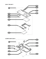
Страница 77: ...19 21 23 20 22 24 3 4 8 9 11 13 14 15 16 17 12 10 7 6 5 Upper case B ass y Z305 1 PCB ass y Lower case B ass y 9 12 27 25 BOTTOM VIEW Display unit Battery case ass y 28 29 EXPLODED VIEW AND PARTS LIST COMPONENT ...

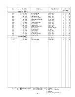
Страница 78: ...13 6418 4160 Label C Z305 C441478 1 1 1 B 14 6418 3870 Battery cover B Z305 C340921 1 1 1 A 15 6418 4030 Screw Z305 C413301 4 1 1 B 16 6418 3851 ROM case Z305 C240743A 1 1 1 A 17 6385 8740 Screw A V331 C41077 7 1 1 B 19 6561 7240 Label D Z305 C441787 1 1 1 B 20 6561 7850 Pen sub ass y C341364 1 1 1 A 21 6561 7200 Label G Z305 C441821 1 1 1 B 22 6390 0432 Cap V332 A310765B 1 1 1 A 23 6540 5580 Dumm...

Страница 79: ...ASE B ASS Y Esc Q W E R T Y U I O P 1 2 3 4 5 6 7 8 9 0 A Tab S D Ctrl Alt F G H J K L Z X C V B Space N M PgUp PgDn End Caps Shift Del Shift Enter Home ON OFF RESET 1 3 1 1 1 2 1 See below 1 5 1 6 1 7 1 8 1 9 1 4 ...

Страница 80: ... 1 1 X 1 4 6418 3940 Button E Z305 C340948 1 1 1 C 1 5 6418 3950 Button F Z305 C340949 1 1 1 C 1 6 6418 3910 Button D Z305 C340930 1 1 1 C 1 7 6418 3740 Button B Z305 C140375 1 1 1 C 1 8 6418 3730 Button A Z305 C140374 1 1 1 C 1 9 6418 3920 Button C Z305 C340931 1 1 1 C Notes Q Quantity used per unit R A Essential R Rank B Stock recommended C Others X No stock recommended AA EA CASIO 2 MB CASIO 4 ...

Страница 81: ... 78 10 1 10 2 10 3 10 4 10 10 5 10 6 10 7 10 4 Z305 1 PCB ASS Y LOWER CASE B ASS Y 5 1 5 2 5 5 5 6 5 4 5 3 5 5 7 5 8 5 9 5 10 ...

Страница 82: ...ip diode SB20 03P TD 2 2 X D16 2390 2513 Schottky diode 1SS319 TE85L 1 1 X EF4 3025 1848 EMI filter NFM51R10P107 1 1 X EF5 3025 1911 EMI filter MEA8020T50R0T002 1 1 X FS1 3632 0658 IC protector F1206A2R00FWTR 1 1 B J1 3502 2075 Card connector PCMCIA 315027068040833 1 1 C J2 3502 2096 RS232C connector 3560 16SR 1 1 C J3 3502 2103 Connector 046239026001800S 1 1 C J4 3502 2089 ROM connector MM20 64B2...

Страница 83: ... X U15 2105 6195 Detector XC61AC2701PR 1 1 X U16 2105 6202 Detector XC61AC1901PR 1 1 X U17 2105 6272 Detector XC61AN2301PR 1 1 X U18 2725 1267 IrDA module TFDS3000TR3 1 1 C U20 U22 2105 6223 D D converter MAX608ESA T 2 2 C U23 2105 6230 D D converter RN5RY202AA TR 1 1 C U26 2105 6237 Regulator RN5RG34AA TR 1 1 C U32 2105 6097 CMOS IC RH5VL45CA T1 1 1 X U50 2105 1568 CMOS IC TC7S32F TE85R 1 1 X U6 ...

Страница 84: ... 82 DISPLAY UNIT 100 101 102 105 109 110 111 112 113 114 115 104 103 107 108 Touch panel ass y LCD module 110 2 110 1 ...

Страница 85: ...05 C441769 1 1 1 B 108 6561 7290 Tape N Z305 C441767 1 1 1 B 109 6418 4090 Speaker spacer Z305 C441466 1 1 1 C 110 3335 6529 LCD module MD400TN01 E2 1 1 A 111 3831 1071 Micro Speaker 20S2W1 1 1 C 112 6418 4280 Tape G Z305 C441565 1 1 1 C 113 6561 7310 Plate C Z305 C441760 1 1 1 C 114 6418 3720 Lower case A Z305 C140372 1 1 1 B 115 6396 7660 Screw A L564 A310044 13 6 6 B LCD MODULE 110 1 5861 3076 ...

Страница 86: ...32 Software CDZ305AA01A 1 1 C 3335 6546 Software CDZ305AA03A 1 1 C JIG 1909 2389 RS232C test connector RS JIG 232C 1909 2391 3 pin test cable RS JIG 3PIN 1909 2388 RAM card XC 110 Notes Q Quantity used per unit R A Essential R Rank B Stock recommended C Others X No stock recommended AA EA CASIO 2 MB CASIO 4 MB 84 ...

Страница 87: ...MA0300171A ...

Отзывы: