background image

1002-6

Engine Oil

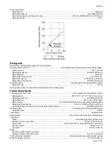
THE CASE/AKCELA No. 1 engine oil is recommended

for  your  engine.  This  oil  ensures  proper  lubrication  of

your engine for all operating conditions.
If the CASE/AKCELA Multigrade "No. 1 ENGINE OIL"

cannot be obtained, use the oil corresponding to one of

the following categories: ACEA E7. API CI-4.

CP02N001

Oil viscosity / Oil range

CT02M001

1) With mineral base
(2) With semi-synthetic base
(3) With synthetic base

3

3

1

2

2

Issued 11-15

Содержание CX350B

Страница 1: ...350B CX370B Crawler Excavator SERVICE MANUAL Crawler Excavator CX350B CX370B Part number 47945155 English November 2015 2015 CNH Industrial Italia S p A All Rights Reserved SERVICE MANUAL Part number 47945155 ...

Страница 2: ...d installation of the injectors 3005 SM350B3005 0EN Fuel engine system 4 ELECTRICAL SYSTEM Service connector kit 4000 Electrical and engine functions and service support 4001 Removal and installation of the starter motor 4004 Removal and installation of the alternator 4005 Electrical equipment and electrical circuit diagrams 4020 Engine error code DTC 4021 Main body error code DTC 4022 Troubleshoo...

Страница 3: ...0B8019 0EN SM350B370B8020 0EN SM350B370B8030 0EN 9 UPPERSTRUCTURE Removal and installation of the counterweight 9002 SM350B9002 0EN Removal and installation of the boom dipper and bucket 9003 SM350B9003 0EN Removal and installation of the seat 9004 SM130B9004 0EN Removal and installation of the cab and cab equipment 9005 SM130B9005 0EN Air conditioner functions and troubleshooting 9006 SC210B9006 ...

Страница 4: ...CNH Copyright 2006 CNH France S A Printed in France February 2006 Lep 7 27691EN 1001 SAFETY GENERAL INFORMATION AND TORQUE SPECIFICATIONS Section 1001 Find manuals at https best manuals com ...

Страница 5: ...ETY 4 STANDARD TORQUE DATA FOR CAP SCREWS AND NUTS 6 WARNING This symbol is used in this manual to indicate important safety messages Whenever you see this symbol carefully read the message that follows as there is a risk of serious injury Find manuals at https best manuals com ...

Страница 6: ...Y BEARINGS WITH COMPRESSED AIR Needle bearings Before you press needle bearings in a bore always remove any metal protrusions in the bore or edge of the bore Before you press bearings into position put petroleum jelly on the inside and outside diameter of the bearings Gears Check all gears for wear and damage Replace gears that have wear or damage Oil seals O rings and gaskets Always install new o...

Страница 7: ... messages Read all safety signs on machine Clear the area of other persons Learn and practice safe use of controls before operating It is your responsibility to understand and follow manufacturers instructions on machine operation service and to observe pertinent laws and regulations Operator s and Service Manuals may be obtained from your Case dealer WARNING If you wear clothing that is too loose...

Страница 8: ...tection that completely encloses the eyes approved goggles or other approved eye protectors WARNING Use suitable floor service jacks or chain hoist to raise wheels or tracks off the floor Always block machine in place with suitable safety stands WARNING When servicing or repairing the machine keep the shop floor and operator s compartment and steps free of oil water grease tools etc Use an oil abs...

Страница 9: ...n of the cap screw and then tighten Torque table Tighten cap screws and nuts according to the table below if there are no other special instructions Cap Screw Name Size Size M6 M8 M10 M12 M14 M16 M18 M20 Cap Screw Spanner mm 10 13 17 19 22 24 27 30 in 0 39 0 51 0 67 0 75 0 87 0 95 1 06 1 18 Tightening torque Nm 6 9 19 6 39 2 58 8 98 1 156 9 196 1 294 2 lb ft 5 1 14 5 28 9 43 4 72 3 115 7 144 6 217...

Страница 10: ...Copyright 2015 CNHi France S A Printed in France November 2015 1002 SPECIFICATIONS AND SPECIAL TORQUE SETTINGS Section 1002 Find manuals at https best manuals com ...

Страница 11: ...ody dimensions 10 Engine 11 Cooling system 11 Capacity of coolant and lubricants 11 Air conditioning 11 Hydraulic oil filter 11 Fuel filter 11 Operating devices 12 Hydraulic system 13 Swing unit 15 Travel lower body 15 Work Unit 16 New Machine Performance 18 COMPONENT WEIGHT 22 Major component weight 22 Other component weight 24 DIMENSIONS AND WEAR LIMIT OF THE TRACK ASSEMBLY 25 Sprocket 25 Idler ...

Страница 12: ...31 3 Boom cylinder head Boom 31 4 Dipper cylinder foot Boom 32 5 Boom Dipper 32 6 Dipper cylinder head Dipper 33 7 Bucket cylinder foot Dipper 33 8 Connecting rod Dipper 34 9 Compensator Bucket 34 10 Connecting rod Compensator Bucket cylinder head 35 11 Dipper Bucket 36 SPECIAL TORQUE SETTINGS 37 MACHINE OVERALL DIMENSIONS 41 Issued 11 15 ...

Страница 13: ...machine to your Case dealer Fill in the following lines with the required information Type serial number year of manufacture of the machine and the serial numbers of the hydraulic and mechanical components Machine 2 ITP003E 1 Type 2 Serial number Engine Make and type Serial number Serial numbers of the components Hydraulic pump Swing reduction gear Travel reduction gears Control valve 1 2 ...

Страница 14: ...is miscible with standard fluid If used to change standard fluid it is advised to drain the circuit completely before refilling with this fluid CASE AKCELA HYDRAULIC EXCAVATOR FLUID BIO MS 1230 ISO VG 46 DIN 51524 PART 2 HV Transmission component oil Extreme pressure oil used for enclosed transmission components CASE AKCELA GEAR 135H EP SAE 80W 90 API GL 5 MIL L 2105 D MS 1316 ZF TE ML 05A Grease ...

Страница 15: ...f your engine for all operating conditions If the CASE AKCELA Multigrade No 1 ENGINE OIL cannot be obtained use the oil corresponding to one of the following categories ACEA E7 API CI 4 CP02N001 Oil viscosity Oil range CT02M001 1 With mineral base 2 With semi synthetic base 3 With synthetic base 3 3 1 2 2 Issued 11 15 ...

Страница 16: ...in your country check the standard for details Requirements for diesel fuel Although conditions required for the diesel fuel are illustrated above there are other requirements exerting a big influence on its service durability and service life Be sure to observe the following requirements for selecting fuel Sulfur content 2500 ppm or less HFRR 460 mm or less Water content 0 05 wt or less HFRR High...

Страница 17: ...lection of engine oil Use API grade CF 4 or JASO grade DH 1 2 Exchange the engine oil and engine oil filter element by the periodical interval reported on the Operator s Manual 3 Inspect and exchange the EGR parts and fuel injector parts of engine every 3000 hour of use EGR Exhaust Gas Recircultion Maintenance of fuel filters Be sure to use the genuine fuel filters The fuel injection system is pre...

Страница 18: ... mix products of a different origin or brand The same product must be used when topping up the system Environment Before carrying out any maintenance operation on this machine and before disposing of used fluids or lubricants always think of the environment Never throw oil or fluid on the ground and never place it in leaking receptacles Contact your local ecological recycling centre or your CASE D...

Страница 19: ...er shoe CX350B LC and STD type 43 kPa 900 mm 35 43 in grouser shoe CX370B LC and STD type 67 kPa 600 mm 23 62 in grouser shoe CX370B LC and STD type 58 kPa 700 mm 27 55 in grouser shoe CX370B LC and STD type 51 kPa 800 mm 31 49 in grouser shoe Main body dimensions Main body width See machine overall dimensions Main unit length CX350B LC and STD type CX370B LC snd STD type 5910 mm 232 68 in Main un...

Страница 20: ...rnator AC type 24 V 50 A Battery 2x 12V 24V 136 Ah 5 Hr Cooling system Fan type diameter 850 mm 33 5 in suction type 6blades resin steel Pulley ratio 80 reduction Direction of rotation Right viewed from fan side compliant with Radiator capacity 96 0 kW Fin type wavy Fin space 2 0 mm 0 08 in Oil cooler capacity 66 6 kW Fin type Wavy Fin space 1 75 mm 0 07 in Inter cooler capacity 29 9 kW Fin type s...

Страница 21: ...splay full dot liquid crystal Work mode selection status SP H A Instruments full dot liquid crystal except for hour meter Fuel gauge bar graph indicator Engine coolant temperature gauge bar graph indicator Hydraulic oil temperature gauge bar graph indicator Hour meter digital type Machine Status and Warning Alarms full dot liquid crystal and warning tone Items have a warning alarm Lighting Horn el...

Страница 22: ...on integrated 1 Operation method hydraulic pilot method travel swing and operating machine Maximum flow 292 5 L min 77 27 gpm at 1950 min 1 Main relief set pressure standard 34 3 MPa 4975 psi power boost 37 3 MPa 5410 psi Overload set pressure when boom down 27 4 MPa 3974 psi other 39 2 MPa 5685 psi Foot relief set pressure 2 55 MPa 369 85 psi Functions Straight travel circuit Boom up arm 2 pumps ...

Страница 23: ...t B forward left G1 Port C backward right G1 Port D backward left G1 Port T drain port G1 2 Port P pilot port G1 4 Solenoid Valve Maximum flow P B 25 L min 6 60 gpm Other 5 L min 1 32 gpm Rated pressure 4 5 MPa 652 67 psi Port size P T B port G3 8 C1 C2 C3 C4 C5 ports G1 4 Solenoid specifications Operating voltage DC 20 to 32 V Power consumption 17 W max Hand control valve Manufacturer Kawasaki Op...

Страница 24: ...or x2 Fixed displacement axial piston motor Displacement 290 7 170 1 cm3 17 73 10 38 cu in rev Operating pressure 34 3 MPa 4975 psi Operating flow 292 5 L min 77 27 gpm Brake torque 47 38 KNm 34945 Ib ft min including reduction gear Relief valve set pressure 35 8 to 37 8 MPa 5192 to 5482 psi Automatic 2 speed switch over pressure with parking brake 26 5 MPa 3843 psi Reduction gear Planetary gear 2...

Страница 25: ...pper length 3250 mm 127 95 in 2630 mm 103 54 in 2210 mm 87 00 in Bucket radius 1680 mm 66 14 in Bucket wrist angle 173 Maximum digging radius 11170 mm 439 76 in 10670 mm 420 07 in 10200 mm 401 58 in Maximum digging radius at ground line 10980 mm 432 28 in 10470 mm 412 20 in 9990 mm 393 31 in Maximum digging depth 7340 mm 288 97 in 6730 mm 264 95 in 6300 mm 248 03 in Maximum vertical straight wall ...

Страница 26: ... 10980 mm 432 28 in 10470 mm 412 21 in 9990 mm 393 31 in Maximum digging depth 7340 mm 288 97 in 6730 mm 264 96 in 6300 mm 248 03 in Maximum vertical straight wall digging depth 6350 mm 249 99 in 7150 mm 281 49 in 5970 mm 235 03 in Maximum digging height 10370 mm 408 26 in 10320 mm 406 3 in 9850 mm 387 8 in Maximum dump height 7230 mm 284 64 in 7140 mm 281 1 in 6770 mm 266 54 in Minimum swing radi...

Страница 27: ... Out 41 0 2 0 In Bucket relief Open 41 5 2 0 Close 42 5 2 0 Swing relief Left and right 32 5 2 0 Travel relief Left and right front and back 4th pump relief Pilot pump 3 9 1 0 Option relief For crusher For breaker 3 Natural fall distance position change for each cylinder with no load in 10 min Boom cylinder retraction mm 10 max Arm cylinder extension 15 max Bucket cylinder retraction 20 max Overal...

Страница 28: ...ards and backwards High speed mm 1000 max Low speed 11 Shoe tension amount mm 12 Travel motor leakage amount L min 15 13 Swing ball race bearing move ment distance Up and down mm 2 0 max Left and right 6 5 max 14 Bucket tip movement amount Left and right mm 110 max 15 Recoil spring dimensions Compression ratio mm 779 Free 892 16 Coil resistance of each sole noid valve Coil resistance tem perature ...

Страница 29: ...0 In Bucket relief Open 41 5 2 0 Close 42 5 2 0 Swing relief Left and right 32 5 2 0 Travel relief Left and right front and back 4th pump relief Pilot pump 3 9 1 0 Option relief For crusher For breaker 3 Natural fall distance position change for each cylinder with no load in 10 min Boom cylinder retraction mm 10 max Arm cylinder extension 15 max Bucket cylinder retraction 20 max Overall bucket tip...

Страница 30: ...s and backwards High speed mm 1000 max Low speed 11 Shoe tension amount mm 340 360 12 Travel motor leakage amount L min 15 13 Swing ball race bearing move ment distance Up and down mm 2 0 max Left and right 6 5 max 14 Bucket tip movement amount Left and right mm 110 max 15 Recoil spring dimensions Compression ratio mm 779 Free 892 16 Coil resistance of each sole noid valve Coil resistance tem pera...

Страница 31: ...lbs B Upper mechanism including counterweight and turntable bearing CX350B LC and STD type 14040 kg 30952 lbs CX370B LC and STD type 15030 kg 33135 lbs C Counterweight CX350B LC and STD type 6400 kg 14109 35 lbs CX370B LC and STD type 7400 kg 16313 93 lbs D Lower mechanism with standard grouser shoe CX350B LC and STD type 12300 kg 27116 lbs CX370B LC and STD type 12470 kg 27491 lbs E Main Unit Wei...

Страница 32: ...322 lbs CX370B LC and STD type 7840 kg 17284 lbs G Boom including cylinders CX350B LC and STD type 3970 kg 8752 lbs CX370B LC and STD type 4250 kg 9369 lbs H Arm dipper including cylinders and linkage CX350B LC and STD type 1820 kg 4012 lbs CX370B LC and STD type 2090 kg 4607 lbs Issued 11 2015 ...

Страница 33: ... 20 kg 44 lbs Radiator total weight 140 kg 309 lbs Oil cooler 34 kg 75 lbs Radiator 21 1 kg 47 lbs Air cooler 19 9 kg 44 lbs Fuel cooler 1 2 kg 2 65 lbs Idler wheel 165 kg 364 lbs Upper roller 43 kg 95 lbs Lower roller 60 kg 132 lbs Tension damper assembly 254 kg 560 lbs Recoil spring assembly 119 4 kg 263 lbs Grease cylinder assembly 41 3 kg 91 lbs Yoke 39 8 kg 88 lbs Threaded rod 50 3 kg 111 lbs...

Страница 34: ...m Standard value mm Usage limit mm Judgment Solution Sprocket a 83 73 Acceptable Unacceptable Cladding by welding or replacement b Ø Ø660 7 Ø649 2 Acceptable Unacceptable c Ø Ø748 Ø738 Acceptable Unacceptable d Ø Ø732 5 Acceptable Unacceptable e 40 45 Acceptable Unacceptable p 215 9 Acceptable Unacceptable a b c d p e 300 6 10 03 03a ...

Страница 35: ... Ø Ø560 Ø550 Acceptable Unacceptable Cladding by welding or replacement b 22 5 Acceptable Unacceptable c 102 92 Acceptable Unacceptable Shaft d Ø Ø85 Ø84 Acceptable Unacceptable Replacement Bushing d Ø Ø85 Ø86 Acceptable Unacceptable Replacement e 82 81 Acceptable Unacceptable Hub f 24 23 6 Acceptable Unacceptable Replacement e c d a b f 300 6 10 03 03b ...

Страница 36: ... Unacceptable Cladding by welding or replacement b 15 Acceptable Unacceptable c 104 Acceptable Unacceptable Shaft d Ø Ø65 Ø64 Acceptable Unacceptable Replacement Bushing d Ø Ø65 Ø66 Acceptable Unacceptable Replacement e 69 68 Acceptable Unacceptable Thrust plate f 9 8 5 Acceptable Unacceptable Replacement Cover g 15 Acceptable Unacceptable Replacement e d a b f g c 300 6 10 03 03c ...

Страница 37: ...Ø Ø180 Ø170 Acceptable Unacceptable Cladding by welding or replacement b 25 20 Acceptable Unacceptable d 216 224 Acceptable Unacceptable Shaft e Ø Ø75 Ø74 Acceptable Unacceptable Replacement Bushing e Ø Ø75 Ø76 Acceptable Unacceptable Replacement f 82 81 Acceptable Unacceptable Collar g 17 5 17 Acceptable Unacceptable Replacement d e a b f g 300 6 10 03 03d ...

Страница 38: ...r replacement Master bushing c Ø Ø71 Ø67 Acceptable Unacceptable Replacement d Ø Ø47 Acceptable Unacceptable Master pin e Ø Ø46 83 Acceptable Unacceptable Replacement Link pitch f 215 9 220 2 Acceptable Unacceptable Replacement f 863 6 880 8 Acceptable Unacceptable Track bushing c Ø Ø71 Ø67 Acceptable Unacceptable Replacement d Ø Ø47 Acceptable Unacceptable Track pin e Ø Ø47 Acceptable Unacceptabl...

Страница 39: ...t mm Judgment Solution Swing frame a 860 868 Acceptable Unacceptable Boom b 857 855 Acceptable Unacceptable Replacement Clearance c 3 0 5 5 Adjust with shims Acceptable Unacceptable Adjust with shims Pin d Ø Ø110 Ø109 Acceptable Unacceptable Replacement Bushing boom e Ø Ø110 Ø111 5 Acceptable Unacceptable Replacement 10 11 9 3 5 6 8 1 2 4 7 a b c d e SI14004 001 ...

Страница 40: ...89 Acceptable Unacceptable Replacement Bushing boom cylinder e Ø Ø90 Ø91 5 Acceptable Unacceptable Replacement Part name Code Measured dimensions mm Standard value mm Usage limit mm Judgment Solution Boom cylinder top section a 123 120 Acceptable Unacceptable Replacement Boom b 669 665 Acceptable Unacceptable Replacement Clearance c 2 0 3 0 Adjust with shims Acceptable Unacceptable Adjust with shi...

Страница 41: ...ing arm cylinder e Ø Ø100 Ø101 5 Acceptable Unacceptable Replacement Part name Code Measured dimensions mm Standard value mm Usage limit mm Judgment Solution Boom a 392 395 Acceptable Unacceptable Replacement Arm b 387 7 389 Acceptable Unacceptable Replacement Clearance c 4 3 4 9 Adjust with shims Acceptable Unacceptable Adjust with shims Pin d Ø Ø115 Ø114 Acceptable Unacceptable Replacement Bushi...

Страница 42: ...100 Ø99 Acceptable Unacceptable Replacement Bushing arm cylinder e Ø Ø100 Ø101 5 Acceptable Unacceptable Replacement Part name Code Measured dimensions mm Standard value mm Usage limit mm Judgment Solution Arm a 146 152 Acceptable Unacceptable Bucket cylinder foot section b 145 143 Acceptable Unacceptable Replacement Clearance c 1 0 2 5 Adjust with shims Acceptable Unacceptable Adjust with shims P...

Страница 43: ...Ø84 Acceptable Unacceptable Replacement Bushing arm e Ø Ø85 Ø86 5 Acceptable Unacceptable Replacement Part name Code Measured dimensions mm Standard value mm Usage limit mm Judgment Solution Bucket a 401 406 Acceptable Unacceptable Replacement Bucket link b 400 397 Acceptable Unacceptable Replacement Clearance c 1 0 3 5 Adjust with shims Acceptable Unacceptable Adjust with shims Pin d Ø Ø90 Ø89 Ac...

Страница 44: ...t with shims Acceptable Unacceptable Adjust with shims Bucket link d 121 123 Acceptable Unacceptable Replacement Bucket cylinder top section e 120 118 Acceptable Unacceptable Replacement Clearance f 1 0 2 0 Adjust with shims Acceptable Unacceptable Adjust with shims Pin g Ø Ø105 Ø104 Acceptable Unacceptable Replacement Bushing bucket link h Ø Ø105 Ø106 5 Acceptable Unacceptable Replacement Bushing...

Страница 45: ... 400 397 Acceptable Unacceptable Replacement Clearance c 0 8 3 7 Adjust with shims Acceptable Unacceptable Adjust with shims Bushing bucket d 16 10 Acceptable Unacceptable Replacement Pin e Ø Ø90 Ø89 Acceptable Unacceptable Replacement Bushing arm f Ø Ø90 Ø91 5 Acceptable Unacceptable Replacement Bushing bucket g Ø Ø90 Ø91 5 Acceptable Unacceptable Replacement d b a c g f e ...

Страница 46: ...1236 1510 912 1114 8 Counterweight M33 50 1685 1960 1243 1446 9 Turntable frame M24 36 900 1050 664 774 10 Swing unit M24 36 900 1050 664 774 11 Engine Mount M20 30 289 337 213 248 12 Front Bracket M10 17 64 73 47 54 13 Rear Bracket M12 19 109 127 80 93 14 Radiator M10 24 147 176 108 130 15 Hydraulic pump Flange M10 17 64 73 47 54 16 Pump M20 17 367 496 271 366 17 Hydraulic reservoir M16 24 233 27...

Страница 47: ...Issued 04 2010 1002 38 ...

Страница 48: ...Issued 04 2010 1002 39 ...

Страница 49: ...Issued 04 2010 1002 40 ...

Страница 50: ...600 mm pads 3 20 m 3 20 m 3 20 m L with 700 mm pads 3 30 m 3 30 m 3 30 m L with 800 mm pads 3 40 m 3 40 m 3 40 m M 0 48 m 0 48 m 0 48 m CX350B LC type Dippers 2 21 m 2 63 m 3 25 m A 3 51 m 3 50 m 3 26 m B 3 13 m 3 13 m 3 13 m C 11 26 m 11 13 m 11 05 m D 5 91 m 5 91 m 5 91 m E 3 02 m 3 02 m 3 02 m F 1 21 m 1 21 m 1 21 m G 3 42 m 3 42 m 3 42 m H 4 98 m 4 98 m 4 98 m I 4 04 m 4 04 m 4 04 m J 2 60 m 2...

Страница 51: ...This as a preview PDF file from best manuals com Download full PDF manual at best manuals com ...

Отзывы: