background image

8

Screw

6-32 X 1"

(2)

Screw

6-32 X 

3

/

8

"

(2)

Wood

Screw

1" (2)

Drywall Anchor

6-32 (2)

12v Battery

W-72

Control

W-72

Control Holder

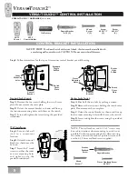
VERSA•TOUCH2™ CONTROL INSTALLATION

CONTROL BRACKET INSTALLATION

Standard Light Switch

Step A. 

Remove the two screws holding the switch cover

plate. Do not remove the cover plate.

Step B.

 Orient the control bracket as shown and line up

the two inner mounting holes with those on the switch.

Step C.

 Insert and tighten the screws using the provided

screwdriver.

Inner

Mounting

holes

Control

Bracket

Standard

Toggle

Switch

Switch

Cover

Plate

Rocker Light Switch

Step A.

 Break off the two tabs by pushing outward.

Step B.

 Remove the two screws holding the switch cover

plate. Do not remove the cover plate.

Step C. 

Orient the control bracket as shown and line up

the two inner mounting holes with those on the switch.

Step D.

 Insert and tighten the screws using the provided

screwdriver.

Outer

Mounting

Holes

Control

Bracket

Rocker

Light

Switch

Switch

Cover

Plate

Wall Installation

Step A. 

Locate a 2x4 wall

stud in a convenient
location.

Step B. 

Orient the control

bracket as shown over the
2x4 stud.

Step C.

 Insert the 1" wood

screws in either the inner
or outer mounting holes
and tighten using the
provided screwdriver.

Decor Ovalhead Screw

6-32 X 1"

Anchor

Panhead

Screw

Drywall Anchor

NOTE: The wall anchors and 6-32 x 1" screws may
be used in situations where mounting to a stud is not
possible. Use the inner mounting holes. After securing
the anchor, discard the anchor’s pointed screws and
use the 6-32 decor ovalhead screws supplied.

SAFETY FIRST: To reduce the risk of electrical shock, this fan must be installed with

an isolating wall control/switch. CAUTION! Do not use with wall dimmer.

Wood

Screw 1"

VERSA•TOUCH2™ HARDWARE 

(not to scale)

Step 8.

 Follow instructions for the type of transmitter control bracket you will be using.

Содержание Silhouette II

Страница 1: ...dure Silhouette II Owner s Manual READ AND SAVETHESE INSTRUCTIONS CONTENTS INTRODUCTION 2 Before You Start 2 Safe Use 2 MOUNTING RECOMMENDATIONS 3 General Guidelines 3 Getting Started 3 CEILING MEDALL...

Страница 2: ...lighting Where wire nuts are employed be sure all bare wires are within the connectors When installing the canopy hatch make sure all wires are within the canopy and that no wires are being pinched Fo...

Страница 3: ...re to provide plenty of clearance to avoid damage from pool cues In kitchens be sure to allow for open cupboard doors to clear the fan blades Do not install a fan close to or over a pool or spa High h...

Страница 4: ...of the ceiling medallion bracket Attach the ceiling medal lion bracket to the outlet box with the screws provided Pack C ensuring that the outlet box wires are not pinched by the washer Ceiling Medal...

Страница 5: ...conductor of power source Secure with wire nut WHITE wire from fan to white NEUTRAL wire in ceiling medallion bracket Secure with wire nut BLACK power wire from fan to BLACK power wire in ceiling med...

Страница 6: ...de Medallions 5 Blades 5 Screw Pack D Blade Screws 21 Screw Pack E Blade Iron Screws 11 Step 6a Sandwich a blade between a blade medallion and blade iron Thread four blade screws Pack D through the sc...

Страница 7: ...k G and tighten until secure using the screwdriver Step7h Remove the lightbulb shield from the socket plate Insert one end of the halogen bulb into the socket Push the end of the socket then insert th...

Страница 8: ...e switch Step D Insert and tighten the screws using the provided screwdriver Outer Mounting Holes Control Bracket Rocker Light Switch Switch Cover Plate Wall Installation Step A Locate a 2x4 wall stud...

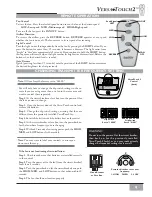
Страница 9: ...eaker and push the HIGH MED and LOW buttons in that order within 20 seconds Step 4 The fan should now function properly CHANGINGTRANSMITTER FREQUENCY SETTING You will only have to change the dip switc...

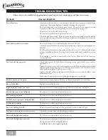
Страница 10: ...ture retaining screws glass shade screws and or lightbulb s Tighten the canopy screws and mounting plate assembly Make sure the wire nuts inside the canopy and switch housing are not touching the meta...

Страница 11: ...is subject to the following two conditions 1 This device may not cause harmful interference 2 This device must accept any interference received including interference that may cause undesired operati...

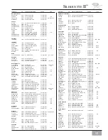
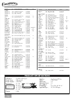
Страница 12: ...80538 FIRESIDE LIGHTING INC 970 669 3540 OWTS COLORADO SPRINGS 80903 HOME LIGHTING INC 719 471 3520 OWTS FORT COLLINS 80525 THE LIGHT CENTER 970 226 3430 OWTS LONGMONT 80501 LUMENAREA COM INC 303 485...

Страница 13: ...CITY ZIP SERVICE CENTER NAME PHONE TYPE NEBRASKA CONTINUED NORFOLK 68701 THE POWER STATION FROHBERG ELEC 402 371 6671 LINCOLN 68510 LINCOLN LIGHTING CTR 402 476 1297 NEVADA SPARKS 89431 EAGLE ELECTRIC...

Страница 14: ...CTRIC 512 837 4704 GIDDINGS 78942 ORSAG S INC 409 542 3167 LUBBOCK 79413 ORECK VACUUMS 806 792 2821 STATE CITY ZIP SERVICE CENTER NAME PHONE TYPE ARLINGTON 76001 P M QUALITY CONT 817 478 2004 TYLER 75...

Страница 15: ...15 SILHOUETTE II NOTES...

Страница 16: ...16 NOTES...

Отзывы: