I
sotope
®
7
Step 2e.
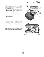
Attach the fan remote wires to the ceiling
bracket wiring by placing the bare end of the wires
side by side and then securing with a wire nut. Test
that the connection is secure by pulling on the wire
nut. Connect in this order:
• GREEN leads from ceiling bracket and motor to
GROUND conductor of power source. Secure with
wire nut as shown in Figure 4.
• WHITE wire from receiver to the WHITE NEUTRAL
conductor wire from the power source. Secure with
wire nut as shown in Figure 4.
• BLACK wire from receiver to the BLACK conductor
wire from the power source. Secure with wire nut
as shown in Figure 4.
GREEN GROUND
WIRES
WHITE
WIRES
BLACK
WIRES
Figure 4
Figure 5
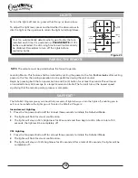
Step 2f.
After making the wire connections, the wires
should be tucked into the outlet box. The wires should
be spread apart, with the three grounded conductor
wires being placed on one side of the fan body and
the power conductor wires being placed onto the
other side of the fan body separating the connections.
CANOPY
SCREWS
Step 2g.
Install two (2) of the canopy screws on the
left side of each end of the mounting plate Figure 5.


