1. 1/4” inputs from power amp output (full range input only).
2. Speakon™ input from power amp (full range or biamp).
Note: the Speakon pin configuration for biamping is:
1+ LF Positive / 1- LF Negative 2+ MF/HF Positive / 2- MF/HF Negative
3. Full Range/Biamp mode switch
4. Speakon™ through wired in parallel with input Speakon™.
5. 1/4” through wired in parallel with 1/4” input.
MULti-Way cRossoveR connections
(non-powered speakers) Use
either 1/4” or Speakon™ cables for connecting to the power amp and daisy chaining
to an additional speaker. For high powered and biamp applications, use Speakon™ cables
only.
sUggestions FoR optiMaL peRFoRMance
• To help control feedback and to correct for venue characteristics, use a graphic EQ.
• For optimal coverage and dispersion, elevate high frequency horn above eye level.
• For optimal headroom, select an amplifier with a power capacity equal to or up to double the
rated program power capacity of the loudspeaker system.
• Ensure all amplifiers are supplied and connected to properly rated AC power circuits.
Underpowering amplifiers may cause premature clipping distortion.
speaKeR caBLes
Use either Carvin’s PRO50S speaker cable for up to 50’ or high-
current 12GA Speakon™ cables for lengths up to 150’. 18GA cables are not recomended.
You can DAISY-CHAIN up to one additional speaker per cable by using the OUTPUT
connector. Be sure the total impedance to the amplifier is not lower than the amplifier’s
minimum impedance.
Speakon
Connector
Standard 1/4” Phone Plug
Tip-Sleeve
Tip
Sleeve
Tip (Positive)
Sleeve (Negative)
Passive Non-Powered Models
1. 1/4” inputs from power amp output.
2. Speakon™ input from power amp.
Note: the Speakon pin configeration is:
1+ LF Positive / 1- LF Negative 2+ not connected / 2- not connected
3. Crossover/Bypass mode switch to bypass internal crossover (must use active cross-
over when in bypass mode)
4. Speakon™ through wired in parallel with input Speakon™.
5. 1/4” through wired in parallel with 1/4” input.
1
2
4
5
3
LSx1523
4 OHMS
3200W PEAK
1600W PROG
800W CONTINUOUS
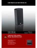
sUBWooFeR cRossoveR connections
1
2
4
5
3
LSx1802
4 OHMS
6400W PEAK
3200W PROG
1600W CONTINUOUS
20Hz
1 kHz
20 kHz
ATTENUA
TION dB
Low Frequency
Mid Frequency
High Frequency
Low
Pass
Filter
Band
Pass
Filter
High
Pass
Filter
LS1503A 300 Watts
75 Watts
50 Watts
LS1523A 700 Watts
120 Watts
80 Watts
1. inpUt/tHRU oUtpUt
Use the balanced XLR or 1/4” connectors featured
on the rear control panel. Using a balanced source will reduce noise which may be
picked up by the cable. You may DAISY-CHAIN as many APS systems as you wish. All
connectors are wired in parallel.
2. eQUaLiZation
The APS powered loudspeakers offer a by passable 3-
band mid sweep equalizer for custom tuning to the acoustical environment. The EQ
system is engineered specifically for the APS, featuring a boost and cut range of ±6dB
to prevent radical adjustments that could otherwise compromise the sound of the
system. The Mid-band sweep is particularly useful for enhancing critical mid range
frequencies for stage monitoring or for cutting certain frequencies to compensate for
room resonances. Press the “EQ IN” switch to activate the equalizer. The BLUE LED
displays when the EQ is active.
3. LeveL contRoL
The LEVEL control adjusts the output volume of the
APS. Start by setting the LEVEL at “0”. Weak input signals can be boosted by set-
ting the LEVEL at “+6”. Strong signals can be reduced by turning the LEVEL toward
“-12”. The RED LED will flash if the internal power amps start to clip. Turn the LEVEL
control down to avoid clipping. Damage to the drivers can result from operating at a
level where the RED CLIP LED is constantly illuminated.
4. poWeR/pRotect/cLip inDicatoR
Power up your audio source
first, then turn on the APS with the power switch. When the system is active, the
LED will indicate GREEN. When shutting down turn off the APS first, then turn off
the mixer. If any of the power amps are clipping, the LED will indicate RED and you
should reduce the output level. If the system should go into protect mode, the LED will
indicate YELLOW and the power amps will shut off. This may occur if; a) the system
is overheated due to clipping the power amps for an extended period of time, b) one of
the internal drivers developed a short or c) the power amps require service.
5. poWeR
Push this switch to the UP position to apply power to the unit. The
POWER LED will light to show the system is on.
6. ac poWeR
Use a standard grounded AC cord. Whenever possible, use
dedicated circuits for powered speakers. The powered speakers are available in either
120V or 240V models.
aps Bi-aMp/tRi-aMp ReaR paneL:
CAUTION
±
TO PREVENT ELECTRICAL SHOCK DO NOT DEFEAT THE
SAFETY GROUND ON THE POWER CORD. DO NOT REMOVE COVER.
NO USER SERVICEABLE PARTS INSIDE. WARNING
±
TO PREVENT FIRE
OR SHOCK HAZARD DO NOT EXPOSE TO RAIN OR MOISTURE. REFER
SERVICING TO QUALIFIED PERSONNEL.
CAUTION
RISK OF ELECTRIC SHOCK
DO NOT OPEN
!
300VA
120VAC 60Hz
A
US
MADE IN THE
Serial No.
TIME-ALIGNED BI-AMP SYSTEM
LOW
MID SWEEP
HIGH
0
+6
-12
00
+6
-6
1kHz
5kHz
100Hz
300 W RMS
MID
+3
-3
LEVEL
0
+6
-6
+3
-3
0
+6
-6
+3
-3
INPUT
THRU OUTPUT
CLIP
RED
PROTECT
YELLOW
POWER
GREEN
EQ IN
742A
3
1
4
5
6
2
LEVEL
LSx1801A
INPUT
THRU OUTPUT
ACTIVE SUBWOOFER SYSTEM
CLIP
RED
PROTECT
YELLOW
POWER
GREEN
FREQUENCY
OUTPUT
CROSSOVER
BYPASS
CROSSOVER
120Hz
80Hz
700W RMS
HI PASS
CAUTION
±
TO PREVENT ELECTRICAL SHOCK DO NOT DEFEAT THE
SAFETY GROUND ON THE POWER CORD. DO NOT REMOVE COVER.
NO USER SERVICEABLE PARTS INSIDE. WARNING
±
TO PREVENT FIRE
OR SHOCK HAZARD DO NOT EXPOSE TO RAIN OR MOISTURE. REFER
SERVICING TO QUALIFIED PERSONNEL.
CAUTION
RISK OF ELECTRIC SHOCK
DO NOT OPEN
!
700VA
120VAC 60Hz
Serial No.
0
+6
-12
A
US
MADE IN THE
1588A
CAUTION
±
TO PREVENT ELECTRICAL SHOCK DO NOT DEFEAT THE
SAFETY GROUND ON THE POWER CORD. DO NOT REMOVE COVER.
NO USER SERVICEABLE PARTS INSIDE. WARNING
±
TO PREVENT FIRE
OR SHOCK HAZARD DO NOT EXPOSE TO RAIN OR MOISTURE. REFER
SERVICING TO QUALIFIED PERSONNEL.
CAUTION
RISK OF ELECTRIC SHOCK
DO NOT OPEN
!
900VA
120VAC 60Hz
A
US
MADE IN THE
Serial No.
TIME-ALIGNED TRIAMPED SYSTEM
LOW
MID SWEEP
HIGH
0
+6
-12
00
+6
-6
1kHz
5kHz
100Hz
900W RMS
MID
+3
-3
LEVEL
0
+6
-6
+3
-3
0
+6
-6
+3
-3
INPUT
THRU OUTPUT
CLIP
RED
PROTECT
YELLOW
POWER
GREEN
EQ IN
1
4
CAUTION
±
TO PREVENT ELECTRICAL SHOCK DO NOT DEFEAT THE
SAFETY GROUND ON THE POWER CORD. DO NOT REMOVE COVER.
NO USER SERVICEABLE PARTS INSIDE. WARNING
±
TO PREVENT FIRE
OR SHOCK HAZARD DO NOT EXPOSE TO RAIN OR MOISTURE. REFER
SERVICING TO QUALIFIED PERSONNEL.
CAUTION
RISK OF ELECTRIC SHOCK
DO NOT OPEN
!
300VA
120VAC 60Hz
A
US
MADE IN THE
Serial No.
TIME-ALIGNED BI-AMP SYSTEM
LOW
MID SWEEP
HIGH
0
+6
-12
00
+6
-6
1kHz
5kHz
100Hz
300 W RMS
MID
+3
-3
LEVEL
0
+6
-6
+3
-3
0
+6
-6
+3
-3
INPUT
THRU OUTPUT
CLIP
RED
PROTECT
YELLOW
POWER
GREEN
EQ IN
742A
5
6
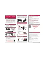
APS HOOK-UP
8
3
7
Lsx1801 sUBWooFeR
7. cRossoveR FReQUency sWitcH
The CROSSOVER FREQUENCY switch
selects the crossover point for the APS. The 120Hz out setting is generally used with small
to mid sized speakers in your setup. Almost all 12” and 15” woofers will benefit from the
120Hz setting. The 80Hz (switch in) setting is generally used with larger 18” woofers.
8. cRossoveR Bypass sWitcH
The crossover bypass switch bypasses the
internal active crossover allowing the use of an outboard active crossover.
9. Hi pass oUtpUt sWitcH
The hi pass output switch changed the output of
the XLR thru output from a parallel of the Input XLR to a hi pass (all frequencies above)
the crossover switch setting. This is good for going to a top cabinet that can not handle
the sub’s low frequencies.
Powered Speakers
TIME IN DI CROSSOVER PHASE SHIFT
*
*
*
APS POWER AMP SPECS:
2-way Bi-amped – LSx1502a/LSx1502ma–LSx1202a/LSx1202ma
350w Continuous/700w Peak RMS (Hi Freq: 50w @ 16 ohms, Lo Freq.
300w @ 8 ohms)
3-way Tri-amped – LSx1503a
425w Continuous/850w Peak RMS (Hi Freq: 50w @ 16ohms, Mid Freq: 75w @ 16 ohms, Lo Freq.
300w @ 8 ohms)
3-way Tri-amped – LSx1523a
900w Continuous/1800w Peak RMS (Hi Freq: 80w @ 16 ohms, Mid Freq: 120w
@ 8 ohms, Lo Freq. 700w @ 4 ohms)
SuB woofer – LSx1801a
700w Continuous/1400w Peak RMS @ 4 ohms
aLL modeLS:
FREQ. RESPONSE: 20 to 20kHz, THD less than .05% @ 90%, .1% at full power,
SLEW RATE: 50V/µs, ACTIVE EQ: ± 6 dB @ 100 Hz, 100 Hz to 5 kHz mid sweep, 10kHz, EQ bypass
switch, (SUB WOOFER: 24dB/Octave @ 80 & 120 Hz) • Relay muting and Speaker Guard™ pro-
tection, Peak and protection & power on indicators, On-Off power switch, Power Req. 120VAC
60 Hz . 240 AC/50Hz model available
Bi amped or Tri amped – active crossovers and power amps
All loudspeaker components are Time-Aligned
for greater intelligibility and clarity
Figure 2
Carvin’s APS (Active Powered Systems) amplification packs take the guesswork out
of selecting the ideal power source to drive your loudspeakers. With bi-amped and
tri-amped models designed to handle the most demanding applications, the APS am-
plifiers are perfectly mated with—the LSx1502A, LSx1503A, and LSx1523A—creat-
ing optimally designed powered loudspeaker systems that are ready for anything you
throw at them. There’s even one APS power pack created specifically to generate the
bone crushing impact of our LSx1801A subwoofer. APS-based LS loudspeaker sys-
tems make setup and operation easier as well, with less gear to haul. Feed your mixer’s
output directly to these loudspeaker systems, and you’re ready to rock!
ACTIVE POWERED SYSTEMS
APS
ACTIVE POWERED SYSTEMS
APS
20Hz
1 kHz
20 kHz
ATTENU
AT
ION dB
Low Frequency
High Frequency
Low
Pass
Filter
High
Pass
Filter
300 Watts
LS1502A
50 Watts
9
RISK OF ELECTRIC SHOCK
DO NOT OPEN
IMPORTANT! FOR YOUR PROTECTION, PLEASE READ THE FOLLOWING:
WATER AND MOISTURE: Do not expose this appliance to rain or moisture. Do not use this apparatus near water (in a wet basement,
near a swimming pool, bathtub etc). Care should be taken so that liquids are not spilled or splashed onto the unit. Do not place
objects filled with liquids such as beverage containers on this apparatus.
POWER SOURCES: The appliance should be connected to a power supply only of the type described in the operating instruc-
tions or as marked on the unit. Unplug during lightning storms.
GROUNDING OR POLARIZATION: Precautions should be taken so that the grounding or polarization means of an appliance
is not defeated.
POWER CORD: Power supply cords should be routed so that they are not likely to be walked on or pinched by items placed
upon or against them, paying particular attention to cords at plugs and the point where they exit from the appliance. The plug
or power inlet is the disconnect device and shall remain readily operable.
PLACEMENT: Do not block ventilation openings. Do not install near heat sources such as radiators, stoves or other products
that produce heat. Do not install in a confined area. Use only mounting hardware such as brackets and tripods recommended
by the manufacturer.
SERVICING: The user should not attempt to service the unit. All servicing should be referred to qualified service personnel.
FUSING: If your unit is equipped with a fuse receptacle, replace only with the same type fuse. Refer to replacement text on
the unit for correct fuse type.
This symbol is intended to alert
the user to the presence of
uninsulated “dangerous voltage”
within the product’s enclosure
that may be of sufficient mag-
nitude to constitute a risk of
electric shock to persons.
This symbol is intended to alert the
user to the presence of important
operating and maintenance (servic-
ing) instructions in the literature
accompanying the appliance.
LIMITED WARRANTY
Your Carvin product is guaranteed against failure for 3 YEARS unless otherwise stated. Carvin will service
and supply all parts at no charge to the customer providing the unit is under warranty. Shipping costs are
the responsibility of the customer. CARVIN DOES NOT PAY FOR PARTS OR SERVICING OTHER THAN OUR
OWN. A COPY OF THE ORIGINAL INVOICE IS REQUIRED TO VERIFY YOUR WARRANTY. This warranty
does not cover, and no liability is assumed, for damage due to: natural disasters, accidents, abuse, loss of
parts, lack of reasonable care, incorrect use, or failure to follow instructions. This warranty is in lieu of all
other warranties, expressed or implied. No representative or person is authorized to represent or assume
for Carvin any liability in connection with the sale or servicing of Carvin products. CARVIN SHALL NOT BE
LIABLE FOR INCIDENTAL OR CONSEQUENTIAL DAMAGES.
When RETURNING merchandise to the factory, you must call for a return authorization number. If your
unit is out of warranty, you will be charged the current FLAT RATE for parts and labor to bring your unit
up to factory specifications.
HELP SECTION
1) UNIT WILL NOT TURN ON: Check the power to the AC cord. Check for tripped circuit breakers,
unplugged extension cords or power-strip switches that may be turned off. Check the fuse or circuit breaker
on the unit if available. If the fuse has been replaced with the proper value and the fuse fails again, or the
internal circuit breaker activates after reset, the unit will require servicing.
2) NO OUTPUT with POWER light ON: Shipping damage will be the primary reason for your product to not
function properly. Please give us a call to help you determine the problem.
3) KEEP YOUR UNIT LOOKING NEW: Use only a dry cloth to wipe the control and venting areas. Surfaces
without openings may be cleaned with a damp cloth.
THIS UNIT CONTAINS HIGH VOLTAGE INSIDE!
REFER SERVICING TO A QUALIFIED TECHNICIAN
CAUTION
typicaL LoUDspeaKeR iMpeDance conFigURations
Individual speaker or speaker cabinet wiring examples for total impedance.