


SC-411RD-10
Installation and Operating Instructions
Page 3 of 12
CP5094C
7/30/12
GENERAL DESCRIPTION
The SC-411RD Remote Light Control/Siren is a premium unit designed for dual 100W speaker use. The pri-
mary operating modes are Radio, Cycler, Standby, Yelp, Wail, and Phaser. A Noise Canceling PA Override
and push-button Horn Override are available in all modes except Radio. A push-button is provided for toggling
between Wail, Yelp, and Phaser tones, and Manual siren control in silent modes. The Phaser tone can be
optionally replaced by Two-Tone or disabled entirely. Auxiliary inputs are provided for connection to horn ring
circuit or switch. A latching siren cutout input is provided for connection to a door switch, etc. to stop siren tones
when exiting the vehicle. PA volume control is on the front panel while Radio volume control is on the amplifier.
The front panel is backlit with LED's for night visibility, dimmable with a front panel switch and/or connection to
dash lights. The siren circuits utilize short circuit, high voltage, and reverse polarity protection for maximum
service life. An indicator light on face is provided for siren output diagnostics.
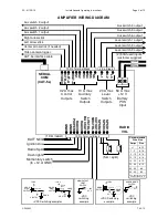
The SC-411RD also provides a 4-position lever switch with LED indicators for primary lighting system control of
up to 50 amps total and automatic siren tone in last position. Six programmable lighted push-button switches
with replaceable legends provide auxiliary lighting or other device control up to 10 amps per switch. Each out-
put is fused and monitored with visual and audible indicators for diagnostics. An alert periodically sounds (may
be disabled) when outputs are on to help prevent leaving lights on unintentionally. A video camera trigger output
is activated with the lever switch or programmed auxiliary switches. Two switches are dedicated to arrow stick
control (left, right, center) with function indication and specific control outputs.
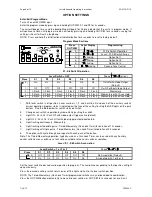
All optional settings are programmed from the remote head face. These settings are synchronized between the
head and amplifier using our QuickClone™ duplication technology, a quick-copy feature for simple transfer of
option setting among multiple heads and amplifiers for efficient fleet installations.
SPECIFICATIONS
Siren Section
Input Voltage
10 - 16 VDC (negative ground)
Input Current
16 AMPS (@14 VDC - dual 100W speakers)
Standby Current
Less than 300 ma
Audio Frequency
200Hz - 10 kHz + 3db
Audio Distortion
Less than 7% (@1 kHz - dual 100W speakers)
Audio Output
80 watts (@14 VDC - dual 100W speakers)
Audio Input
400 ohms + 10%
Output Power
210 WATTS RMS MAX. (15 VDC - dual 100W speakers)
Siren Frequency
700Hz - 1500Hz (Two-Tone and Horn = 435 & 585Hz)
Tones /
Cycle Rates
High Voltage Protection
16 - 18 VDC will cause siren output to cease, resume at normal voltage
Short Circuit Current
50 AMPS (supply circuit must be capable of supplying this)
Operating Temp.
-15° F to +140°F
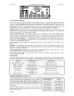
Controls
6-position rotary mode switch (Radio, Cycler, Standby, Yelp, Wail, and Phaser).
Momentary push-button Horn switch.
Momentary push-button Manual/Tone toggle switch.
Momentary push-button Dimming switch.
Enable input (positive) to turn on unit.
Auxiliary siren input programmable for positive or negative operation.
Auxiliary light control input programmable for positive or negative operation.
Cutout input programmable for positive or negative latching operation.
Face-programmable option settings.
Connections (Rem. 12-Term Blk)
(2) Neg, (3) Spkr, (2) Radio, Power, Siren Ctrl, Light Ctrl, Cutout, Backlit (#28-#12 AWG)
Light Control Section
Controls
4-position lever switch with position 3 siren activation and LED indicators
8 - on/off lighted push-button switches with replaceable legends
Current (Lever Switch)
20 AMPS per circuit, 50 AMPS total
Current (Aux. Sw.)
10 AMPS per switch, 30 AMPS total
Connections
(Removable 3-Term Block)
(Removable 10-Term Block)
Power Input - (2) screw terminal inputs (#22 to #6 AWG) 50A max each, external fuse reqd.
Lever Switch - (3) outputs (#22 to #10 AWG), 20A max each
Aux. Switches - (6) outputs (#22 to #12 AWG), 10A max each
Left, right & center arrow stick control outputs (#22 to #12 AWG), 0.2A max each
Video control output (#22 to #12 AWG), 0.2A max
General
Size
Control Head: 6-1/8" X 2-5/8" X 1-1/4"
Amplifier: 8-3/4" X 8-1/4" X 2-1/8"
Shipping Weight
6 LBS.
Horn
Wail
Yelp
Phaser
Two-Tone
109 CPS
13 CPM
190 CPM
15 CPS
60 CPM
Head/Amplifier Interconnect
CAT 5e cable 25ft (supplied)
Control Head Mounting
Flush, surface or bracket mount (supplied)