


27
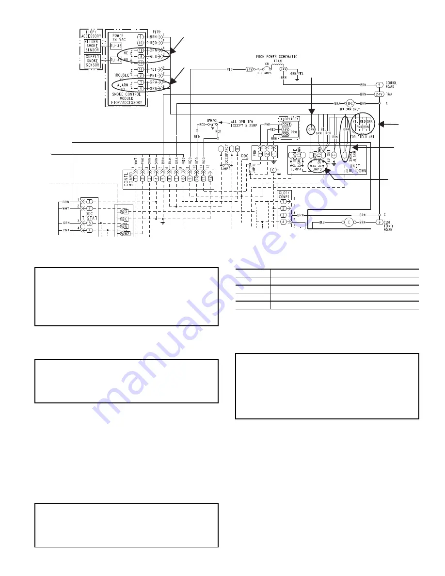
Fig. 56 — Typical Smoke Detector System Wiring
Dirty Controller Test
The dirty controller test checks the controller’s ability to initi-
ate a dirty sensor test and indicate its results.
DIRTY CONTROLLER TEST PROCEDURE
1. Press the controller’s test/reset switch for two seconds.
2. Verify that the controller’s Trouble LED flashes.
Dirty Sensor Test
The dirty sensor test provides an indication of the sensor’s abil-
ity to compensate for gradual environmental changes. A sensor
that can no longer compensate for environmental changes is
considered 100% dirty and requires cleaning or replacing. A
field provided SD-MAG test magnet must be used to initiate a
sensor dirty test. The sensor’s Dirty LED indicates the results
of the dirty test as shown in Table 7.
Table 7 — Dirty LED Test
DIRTY SENSOR TEST PROCEDURE
1. Hold the test magnet where indicated on the side of the
sensor housing for two seconds.
2. Verify that the sensor’s Dirty LED flashes.
Changing the Dirty Sensor Test
By default, sensor dirty test results are indicated by:
• The sensor’s Dirty LED flashing.
• The controller’s Trouble LED flashing.
• The controller’s supervision relay contacts toggle.
The operation of a sensor’s dirty test can be changed so that the
controller’s supervision relay is not used to indicate test results.
When two detectors are connected to a controller, sensor dirty
test operation on both sensors must be configured to operate in
the same manner.
TO CONFIGURE THE DIRTY SENSOR TEST OPERATION
1. Hold the test magnet where indicated on the side of the
sensor housing until the sensor’s Alarm LED turns on and
its Dirty LED flashes twice (approximately 60 seconds).
A
E
F
C
D
B
IMPORTANT: Failure to follow this ALERT can result
in an unnecessary evacuation of the facility.
This test places the duct detector into the alarm state.
Unless part of the test, disconnect all auxiliary equipment
from the controller before performing the test. If the duct
detector is connected to a fire alarm system, notify the
proper authorities before performing the test.
IMPORTANT: Failure to follow this ALERT can result in
an unnecessary evacuation of the facility.
Pressing the controller’s test/reset switch for longer than
seven seconds will put the duct detector into the alarm state
and activate all automatic alarm responses.
IMPORTANT: Failure to follow this ALERT can result in
an unnecessary evacuation of the facility.
Holding the test magnet against the sensor housing for more
than seven seconds will put the duct detector into the alarm
state and activate all automatic alarm responses.
FLASHES DESCRIPTION
1
0-25% dirty. (Typical of a newly installed detector)
2
25-50% dirty
3
51-75% dirty
4
76-99% dirty
IMPORTANT: Failure to follow this ALERT can result
in an unnecessary evacuation of the facility.
Changing the dirty sensor test operation will put the
detector into the alarm state and activate all automatic
alarm responses. Before changing dirty sensor test opera-
tion, disconnect all auxiliary equipment from the control-
ler and notify the proper authorities if connected to a fire
alarm system.
Содержание WeatherMaster 50HC04
Страница 32: ...32 Fig 63 RTU Open Overlay for Economizer Wiring ...
Страница 33: ...33 Fig 64 VFD Overlay for W2770 Controller Wiring ...
Страница 85: ...85 Fig B 50HC A04 A06 PAC Control Diagram 208 1 60 208 230 3 60 460 575 3 60 APPENDIX D WIRING DIAGRAMS ...
Страница 86: ...86 Fig C 50HC A07 PAC Control Diagram 208 230 3 60 460 575 3 60 APPENDIX D WIRING DIAGRAMS ...
Страница 89: ...89 Fig F 50HC D08 D09 PAC Control Diagram 208 230 3 60 460 575 3 60 APPENDIX D WIRING DIAGRAMS ...
Страница 90: ...90 Fig G 50HC D11 PAC Control Diagram 208 230 3 60 460 3 60 575 3 60 APPENDIX D WIRING DIAGRAMS ...
Страница 91: ...91 Fig H 50HC D12 PAC Control Diagram 208 230 3 60 460 575 3 60 APPENDIX D WIRING DIAGRAMS ...
Страница 92: ...92 Fig I 50HC D14 PAC Control Diagram 208 230 3 60 460 3 60 575 3 60 APPENDIX D WIRING DIAGRAMS ...
Страница 93: ...93 Fig J 50HC A04 A06 PAC Power Diagram 208 230 1 60 APPENDIX D WIRING DIAGRAMS ...
Страница 94: ...94 Fig K 50HC A04 A06 PAC Power Diagram 208 230 3 60 460 3 60 575 3 60 APPENDIX D WIRING DIAGRAMS ...
Страница 95: ...95 Fig L 50HC A07 PAC Power Diagram 208 230 3 60 460 3 60 575 3 60 APPENDIX D WIRING DIAGRAMS ...
Страница 98: ...98 Fig O 50HC D07 PAC Power Diagram 575 3 60 6 Ton 2 Stage with Dehumidification APPENDIX D WIRING DIAGRAMS ...
Страница 99: ...99 Fig P 50HC D08 D09 PAC Power Diagram 208 230 3 60 460 3 60 575 3 60 APPENDIX D WIRING DIAGRAMS ...
Страница 100: ...100 Fig Q 50HC D11 PAC Power Diagram 208 230 3 60 APPENDIX D WIRING DIAGRAMS ...
Страница 101: ...101 Fig R 50HC D11 PAC Power Diagram 460 3 60 575 3 60 APPENDIX D WIRING DIAGRAMS ...
Страница 102: ...102 Fig S 50HC D12 PAC Power Diagram 208 230 3 60 460 3 60 575 3 60 APPENDIX D WIRING DIAGRAMS ...
Страница 103: ...103 Fig T 50HC D14 PAC Power Diagram 208 230 3 60 APPENDIX D WIRING DIAGRAMS ...
Страница 104: ...104 Fig U 50HC D14 PAC Power Diagram 460 3 60 575 3 60 APPENDIX D WIRING DIAGRAMS ...
Страница 109: ...109 Fig Z 50HC D12 PAC Control Diagram 230 460 575 3 60 with Humidi MiZer System APPENDIX D WIRING DIAGRAMS ...
Страница 110: ...110 Fig AA 50HC D14 PAC Control Diagram 230 460 575 3 60 with Humidi MiZer System APPENDIX D WIRING DIAGRAMS ...
Страница 111: ...111 Fig AB 50HC A04 A06 PAC Power Diagram 208 230 1 60 with Humidi MiZer System APPENDIX D WIRING DIAGRAMS ...
Страница 112: ...112 Fig AC 50HC A04 A06 PAC Power Diagram 208 230 460 3 60 with Humidi MiZer System APPENDIX D WIRING DIAGRAMS ...
Страница 113: ...113 Fig AD 50HC A04 A06 PAC Power Diagram 575 3 60 with Humidi MiZer System APPENDIX D WIRING DIAGRAMS ...
Страница 114: ...114 Fig AE 50HC A07 PAC Power Diagram 208 230 460 3 60 with Humidi MiZer System APPENDIX D WIRING DIAGRAMS ...
Страница 115: ...115 Fig AF 50HC A07 PAC Power Diagram 575 3 60 with Humidi MiZer System APPENDIX D WIRING DIAGRAMS ...
Страница 116: ...116 Fig AG 50HC D08 D09 PAC Power Diagram 208 230 460 3 60 with Humidi MiZer System APPENDIX D WIRING DIAGRAMS ...
Страница 117: ...117 Fig AH 50HC D08 D09 PAC Power Diagram 575 3 60 with Humidi MiZer System APPENDIX D WIRING DIAGRAMS ...
Страница 118: ...118 Fig AI 50HC D11 PAC Power Diagram 208 230 3 60 with Humidi MiZer System APPENDIX D WIRING DIAGRAMS ...
Страница 119: ...119 Fig AJ 50HC D11 PAC Power Diagram 460 3 60 575 3 60 with Humidi MiZer System APPENDIX D WIRING DIAGRAMS ...
Страница 121: ...121 Fig AL 50HC D14 PAC Power Diagram 208 230 3 60 with Humidi MiZer System APPENDIX D WIRING DIAGRAMS ...
Страница 122: ...122 Fig AM 50HC D14 PAC Power Diagram 460 3 60 with Humidi MiZer System APPENDIX D WIRING DIAGRAMS ...
Страница 123: ...123 Fig AN 50HC D14 PAC Power Diagram 575 3 60 with Humidi MiZer System APPENDIX D WIRING DIAGRAMS ...
Страница 124: ...124 Fig AO PremierLink System A04 A06 Wiring Diagram APPENDIX D WIRING DIAGRAMS ...
Страница 125: ...125 Fig AP RTU Open System Control A04 A06 Wiring Diagram APPENDIX D WIRING DIAGRAMS ...
Страница 126: ...126 Fig AQ PremierLink System A07 D14 Wiring Diagram APPENDIX D WIRING DIAGRAMS ...
Страница 127: ...127 Fig AR RTU Open A07 D14 Wiring Diagram APPENDIX D WIRING DIAGRAMS ...