


18
Replacing the Compressor
NOTE: Only factory-trained service technicians should remove
and replace compressor units.
Compressors using Puron refrigerant contain a polyolester
(POE) oil. This oil has a high affinity for moisture. Do not re-
move the compressor’s tube plugs until ready to insert the unit
suction and discharge tube ends.
Compressor Rotation
NOTE: When the compressor is rotating in the wrong direction,
the unit makes an elevated level of noise and does not provide
cooling.
On 3-phase units with scroll compressors, it is important to be cer-
tain compressor is rotating in the proper direction. To determine
whether or not compressor is rotating in the proper direction:
1. Connect service gages to suction and discharge pressure
fittings.
2. Energize the compressor.
3. The suction pressure should drop and the discharge pres-
sure should rise, as is normal on any start-up.
NOTE: If the suction pressure does not drop and the discharge
pressure does not rise to normal levels:
4. Note that the evaporator fan is probably also rotating in
the wrong direction.
5. Turn off power to the unit.
6. Reverse any two of the three unit power leads.
7. Reapply electrical power to the compressor.
8. The suction pressure should drop and the discharge pres-
sure should rise which is normal for scroll compressors on
start-up.
9. Replace compressor if suction/discharge pressures are not
within specifications for the specific compressor.
Filter Drier
Replace the filter drier whenever refrigerant system is exposed
to atmosphere. Only use factory-specified liquid-line filter dri-
ers with working pressures no less than 650 psig (4482 kPa).
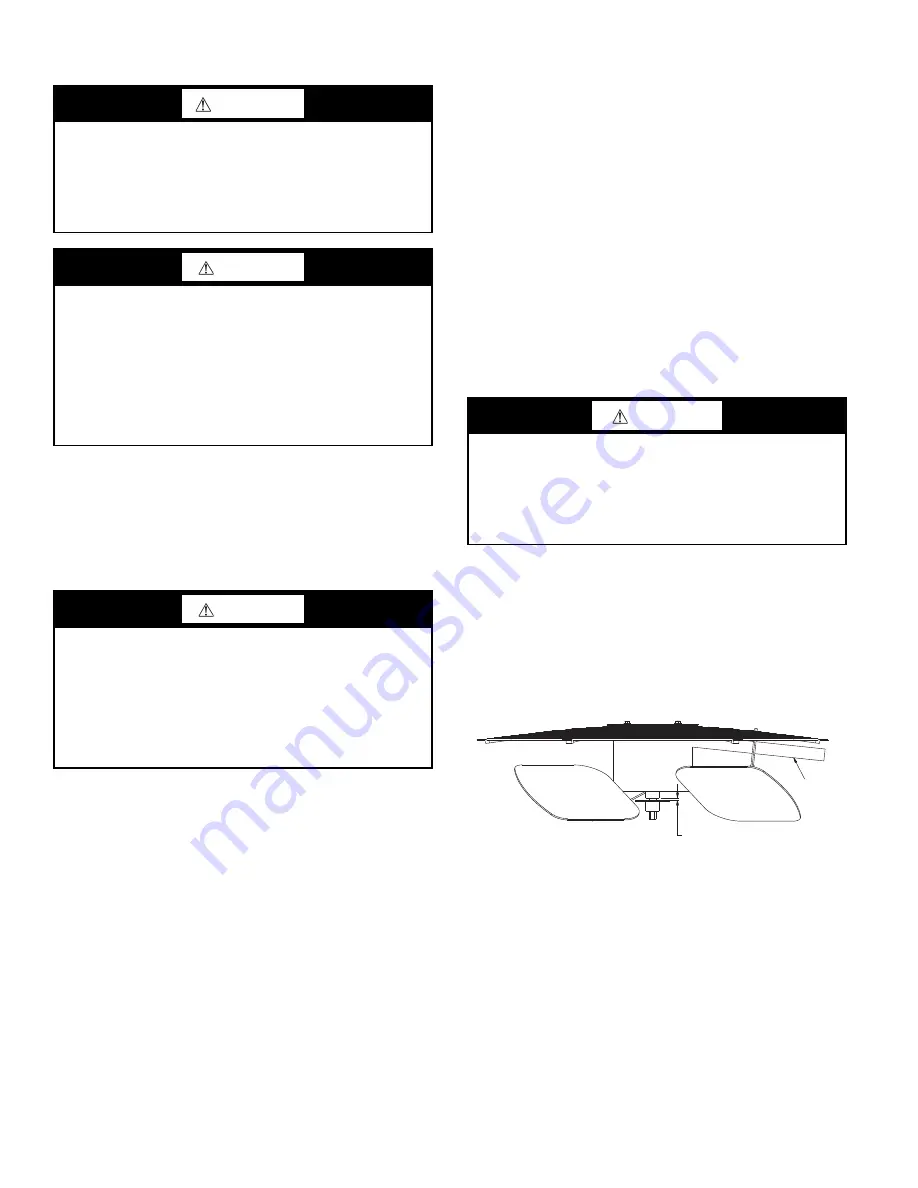
Outdoor Fan Location
See Fig. 22.
1. Shut off unit power supply. Apply lockout/tag-out
procedures.
2. Remove condenser-fan assembly (grille, motor, and fan).
3. Loosen fan hub setscrews.
4. Adjust fan height as shown in Fig. 22.
5. Tighten setscrews to 84 in. lb (9.5 Nm).
6. Replace condenser-fan assembly.
Fig. 22 — Outdoor Fan Adjustment
Troubleshooting Cooling System
Refer to Table 6 for additional troubleshooting topics.
WARNING
FIRE, EXPLOSION HAZARD
Failure to follow this warning could result in death, serious
personal injury and/or property damage.
Never use air or gases containing oxygen for leak testing or
for operating refrigerant compressors. Pressurized mixtures
of air or gases containing oxygen can lead to an explosion.
CAUTION
INSTALLATION SITE DAMAGE
Failure to follow this caution can result in damage to equip-
ment location site.
R-410A refrigerant contains polyolester (POE) oil that can
damage the roof membrane. Caution should be taken to
prevent POE oil from spilling onto the roof surface.
The factory also recommends that the suction and discharge
lines be cut with a tubing cutter instead of using a torch to
remove brazed fittings.
CAUTION
EQUIPMENT DAMAGE HAZARD
Failure to follow this caution can result in premature wear
and damage to equipment.
Scroll compressors can only compress refrigerant if rotat-
ing in the right direction. Reverse rotation for extended
times can result in internal damage to the compressor.
Scroll compressors are sealed units and cannot be repaired
on site location.
CAUTION
EQUIPMENT DAMAGE
Failure to follow this caution can result in equipment dam-
age.
Do not install a suction-line filter drier in liquid line. A liq-
uid-line filter drier designed for use with R-410A refriger-
ant is required on every unit.
CONDUIT
0.14 in. + 0.0 / -0.03
Содержание WeatherMaker 50KCQ A04 Series
Страница 34: ...34 Fig 53 RTU Open Overlay for Economizer Wiring ...
Страница 35: ...35 Fig 54 VFD Overlay for W2770 Controller Wiring ...
Страница 70: ...70 Fig C 50KCQ A04 A05 A06 Control Wiring Diagram 575 3 60 APPENDIX D WIRING DIAGRAMS ...
Страница 71: ...71 Fig D 50KCQ A04 A05 A06 Power Wiring Diagram 208 230 1 60 APPENDIX D WIRING DIAGRAMS ...
Страница 72: ...72 Fig E 50KCQ A04 A05 A06 Power Wiring Diagram 208 230 3 60 APPENDIX D WIRING DIAGRAMS ...
Страница 73: ...73 Fig F 50KCQ A04 A05 A06 Power Wiring Diagram 460 3 60 APPENDIX D WIRING DIAGRAMS ...
Страница 74: ...74 Fig G 50KCQ A04 A05 A06 Power Wiring Diagram 575 3 60 APPENDIX D WIRING DIAGRAMS ...
Страница 75: ...75 Fig H 50KCQ Premier Link Control Diagram APPENDIX D WIRING DIAGRAMS ...
Страница 76: ...76 Fig I 50KCQ RTU Open Control Diagram APPENDIX D WIRING DIAGRAMS ...


