Carrier OMNIZONE 50XCA06 Скачать руководство пользователя страница 36

36

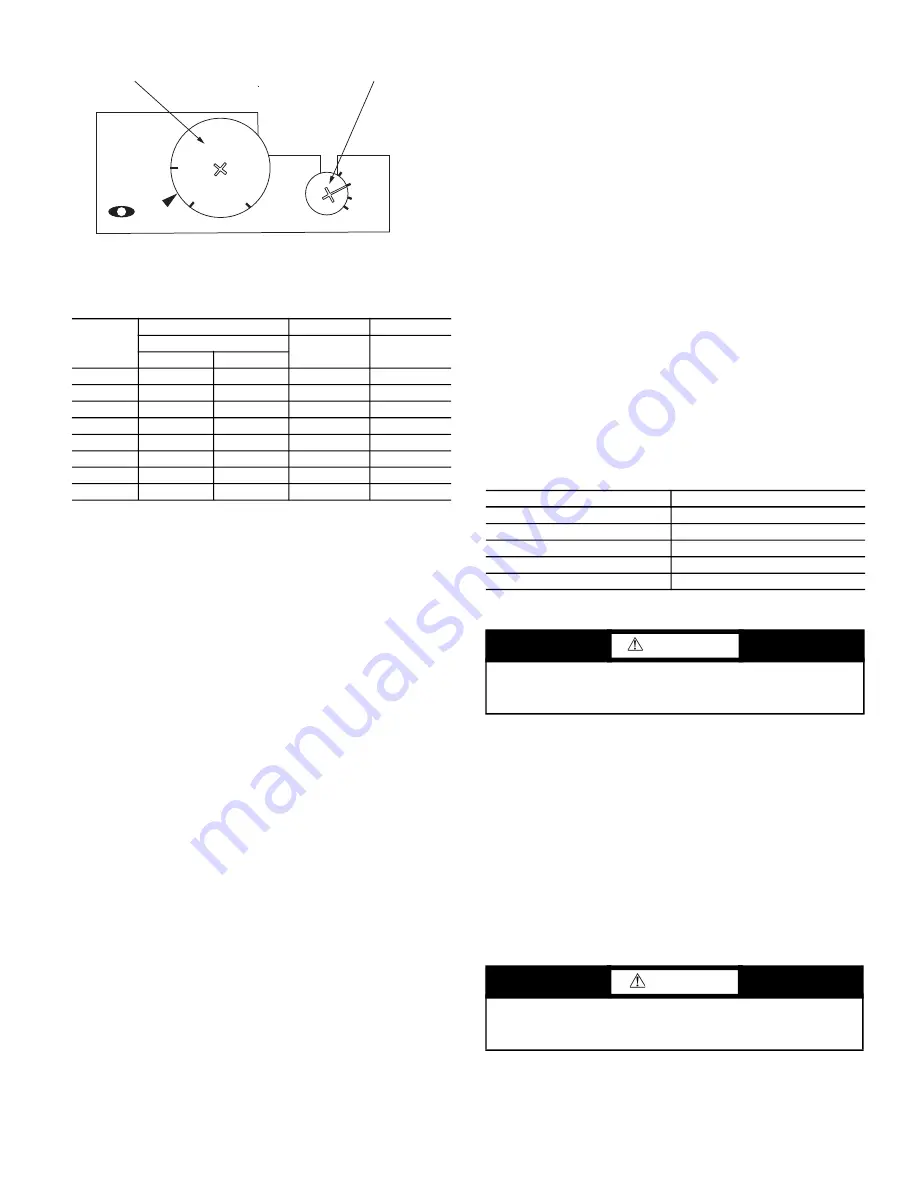
Fig. 24 — Motor Starter Setting

Table 21 — Evaporator and Condenser 

Motor Starter Settings

MAINTENANCE

Cleaning

The unit should be thoroughly cleaned inside and out. Frequency

of  cleaning  will  depend  on  unit  location  and  area  conditions.

Drains must be kept free of dirt and trash. Coils can be cleaned

with a stiff brush or vacuum cleaner. Coil can be reached through

access panels.

Inspection

Check coil baffles for tight fit to prevent air from bypassing the

coil. Check panels for air leakage, particularly those sealing the

fan and coil compartments. Check for loose electrical connections,

proper refrigerant charge, and refrigerant piping leaks.

Air Filters

Air filters may be installed on the condenser air inlet. Air filters

should be replaced  or cleaned  on a regular basis  depending on

how dirty the operating environment is. Failure to clean air filters

regularly will result in loss of unit performance and possible nui

-

sance tripping of the high-pressure switch.

Condensate Drain

The drain pan and trap should be cleaned at least twice per year.

After cleaning, test the condensate drain for proper operation by

pouring a bucket of water into the condensate drain pan. The water

should flow out immediately and evenly.

Checking System Charge

NOTE: Condenser and evaporator airflow must be properly set

before checking system charge.

The 50XCA units are shipped with full operating charge. If re

-

charging is necessary:

1. Insert thermometer bulb in insulating rubber sleeve on liquid

line near filter drier. Use a digital thermometer for all tem

-

perature measurements. DO NOT use a mercury or dial-type

thermometer.

2. Connect refrigerant pressure gage to discharge line near com

-

pressor.

3. After unit condition have stabilized, read head pressure on

discharge line gage.

4. NOTE: Operate unit a minimum of 15 minutes before check

-

ing charge.

5. From standard Pressure-Temperature chart for R-410A, find

equivalent saturated condensing temperature.

6. Read liquid line temperature on thermometer; then subtract

from  saturated  condensing  temperature.  The  difference

equals subcooling temperature.

7. Compare the subcooling temperature with the normal tem

-

perature listed in Table 22. If the measured liquid line tem

-

perature  does  not  agree  with  the  required  liquid  line

temperature, ADD  refrigerant  to  raise  the  temperature  or

REMOVE refrigerant (using standard practices) to lower the

temperature (allow a tolerance of ± 3°F).

Example:

Head pressure (from gage)416.4 psig

Saturated condensing temp (from chart)120°F

Liquid line temp (from thermometer)100°F

Subcooling (by subtraction)20°F

Table 22 — Subcooling Temperature

*Saturated condensing temperature at compressor minus liquid line tem-

perature.

NOTE: Do not vent or depressurize unit refrigerant to atmosphere.

Remove and recover refrigerant following accepted practices.

Access Panel Removal

TOP PANEL
Remove 3 to 6 screws, pull out panel, and remove.
CONTROL PANEL
Remove 4 screws and remove the panel.
BOTTOM PANEL
Remove 3 to 6 screws in bottom panel and lift up to remove the

panel.

Evaporator-Fan Motor Removal

NOTE: Motor power wires need to be disconnected from control

box terminals before motor is removed from unit.

HP

208-230 V

460 V

575 V

FLA

FLA

FLA

208V

230V

0.50

1.8

2.2

1.1

0.9

0.75

2.5

2.6

1.3

1.0

1.00

3.4

3.0

1.5

1.1

1.50

4.6

4.2

2.1

1.6

2.00

6.0

5.6

2.8

2.1

3.00

9.2

8.6

4.3

3.4

5.00

14.5

13.6

6.8

5.4

7.50

21.5

19.4

9.7

7.5

1.9

1.6

1.3

M

M-O

A-O

A

RESE

T-

O

CLASS 20

TEST

OVERLOAD SETPOINT WHEEL

MOTOR OVERLOAD RESET WHEEL

UNIT 50XCA

SUBCOOLING*

06

20°

08

17°

12-14

21°

16

18°

24

25°

WARNING

To  prevent  personal  injury,  wear  safety  glasses  and  gloves

when handling refrigerant. Do not overcharge system — this

can cause compressor flooding.

CAUTION

Before  attempting  to  remove  fan  motors  or  motor  mounts,

place a piece of plywood over evaporator coils to prevent coil

damage.

Содержание OMNIZONE 50XCA06

Страница 1: ...Fan Adjustment 34 Pulley Alignment 34 Belt Tension Adjustment 35 Changing Fan Wheel 35 Fan Bearing Replacement 35 Concentric Alignment 35 Evaporator and Condenser Motor Starter Setting after Lockout...

Страница 2: ...he nameplate electrical requirements match the available power supply DO NOT place the unit in a horizontal position Do not allow re frigerant lines to come into contact with wiring or sharp objects o...

Страница 3: ...NT VIEW CONTROL BOX DISCONNECT OPT TOP VIEW SIZE 06 RIGHT VIEW REAR VIEW TOP VIEW SIZE 08 EVAP ACCESS PANEL CONDENSER ACCESS PANEL NOTE Dimensions are in inches UNIT 50XCA WIDTH HEIGHT DEPTH COND SECT...

Страница 4: ...ACCESS PANEL CONDENSER ACCESS PANEL INDOOR SUPPLY AIR FLOW CONDENSER DISCHARGE CONTROL BOX FRONT VIEW NOTE Dimensions are in inches UNIT 50XCA WIDTH HEIGHT DEPTH COND SECTION EVAP SECTION EVAP RETURN...

Страница 5: ...U J U CONDENSER ACCESS PANEL CONDENSER DISCHARGE RIGHT VIEW FRONT VIEW REAR VIEW TOP VIEW L NOTE Dimensions are in inches UNIT 50XCA WIDTH HEIGHT DEPTH COND SECTION EVAP SECTION EVAP RETURN DUCT COND...

Страница 6: ...ACCESS PANEL CONDENSER ACCESS PANEL INDOOR SUPPLY AIR FLOW CONDENSER DISCHARGE CONTROL BOX FRONT VIEW NOTE Dimensions are in inches UNIT 50XCA WIDTH HEIGHT DEPTH COND SECTION EVAP SECTION EVAP RETURN...

Страница 7: ...DENSER DISCHARGE RIGHT VIEW FRONT VIEW REAR VIEW TOP VIEW CONDENSER ACCESS PANEL CONTROL BOX NOTE Dimensions are in inches UNIT 50XCA WIDTH HEIGHT DEPTH COND SECTION EVAP SECTION EVAP RETURN DUCT COND...

Страница 8: ...8 1 5 5 7 12 5 13 8 8 5 13 5 11 7 18 9 16 2 36 5 16 2 1 25 24 88 0 100 1 31 2 60 5 39 5 81 5 35 8 62 6 5 5 80 38 5 1 5 5 7 14 9 13 8 8 6 8 3 13 2 15 0 16 2 42 0 8 3 2 00 C 5 1 1 2 FLTR 6 8 4 FLTR E D...

Страница 9: ...56 7 5 5 80 32 8 1 5 5 7 12 5 13 8 2 6 13 5 11 7 18 9 16 2 36 5 16 2 1 25 24 88 0 100 1 31 2 60 5 39 5 81 5 35 8 62 6 5 5 80 38 5 1 5 5 7 14 9 13 8 2 6 8 3 13 2 15 0 16 2 42 0 8 3 2 00 V V Q Q N N N...

Страница 10: ...8 1 5 5 7 12 5 13 8 8 5 13 5 11 7 18 9 16 2 36 5 16 2 1 25 24 88 0 100 1 31 2 60 5 39 5 81 5 35 8 62 6 5 5 80 38 5 1 5 5 7 14 9 13 8 8 6 8 3 13 2 15 0 16 2 42 0 8 3 2 00 S T 13 2 U R U R R K J L M A...

Страница 11: ...8 56 7 5 5 80 32 8 1 5 5 7 12 5 13 8 2 6 13 5 11 7 18 9 16 2 36 5 16 2 1 25 24 88 0 100 1 31 2 60 5 39 5 81 5 35 8 62 6 5 5 80 38 5 1 5 5 7 14 9 13 8 2 6 8 3 13 2 15 0 16 2 42 0 8 3 2 00 A F I G H DI...

Страница 12: ...s Quantity Rows Fins in 3 15 4 15 3 15 4 15 4 15 4 15 Fin Block Size H x L in 28x35 28x46 32x60 32x60 32x80 36x80 Face Area sq ft 6 8 8 9 13 3 13 3 17 7 20 RETURN AIR FILTERS Std 1 in Throwaway 2 25 x...

Страница 13: ...ts Obstructions closer than 10 ft to the discharge air pattern can also cause significant recirculation See Fig 12 for recommended duct sizing CONDENSER AIR DUCT The condenser supply and discharge air...

Страница 14: ...LOUVER WIDTHS OVER 30 5 3 1 2 4 1 30 EXHAUST VANE DEFLECTOR CONDENSER INTAKE Access panel for condenser coil cleaning INLET LOUVER DETAIL DISCHARGE LOUVER DETAIL DEFLECTOR DETAIL DIMENSIONS in UNIT 50...

Страница 15: ...50XCA Installation Options Fig 14 Typical Fan Discharge Connections for Multiple Fan Units Provide access for cleaning condenser coil NOTE A min straight duct length Preferred for condenser discharge...

Страница 16: ...must be in accordance with local or NEC National Electrical Code regulations POWER WIRING The units must have adequate overcurrent protection fuses or HACR Heating Air Conditioning and Refrigeration b...

Страница 17: ...8 208 230 3 60 187 253 23 0 149 460 3 60 414 506 11 0 75 575 3 60 518 632 8 0 54 12 208 230 3 60 187 253 15 6 110 15 9 110 460 3 60 414 506 7 8 52 7 1 52 575 3 60 518 632 5 8 39 5 1 39 14 208 230 3 60...

Страница 18: ...5 8 in long screws provided with plenum Install 3 screws along each plenum side and 5 screws along plenum front and rear mounting angles 4 Adjust four way deflection vanes as needed to ensure ade qua...

Страница 19: ...Shaft alignment can be checked by measuring the distance between the shafts at 3 or more locations If the distances are equal then the shafts are parallel 2 Sheave Alignment Fixed sheaves To check th...

Страница 20: ...Solution a From Fig 20 find that deflection force for type A super belt with 5 in small sheave PD is 4 to 51 2 lb b Deflection 16 64 1 4 in c Increase or decrease belt tension until force required for...

Страница 21: ...are installed on the condenser fan before starting the unit CFM ESP in wg 0 00 0 10 0 20 0 30 0 40 0 50 0 60 0 70 0 80 0 90 Rpm Bhp Rpm Bhp Rpm Bhp Rpm Bhp Rpm Bhp Rpm Bhp Rpm Bhp Rpm Bhp Rpm Bhp Rpm...

Страница 22: ...684 0 61 744 0 74 800 0 87 854 1 01 906 1 16 956 1 32 1004 1 48 2950 655 0 58 714 0 71 771 0 83 826 0 97 878 1 12 928 1 27 976 1 43 1023 1 60 3100 688 0 68 745 0 80 799 0 94 852 1 08 902 1 23 950 1 39...

Страница 23: ...5300 503 0 88 552 1 04 597 1 20 640 1 37 680 1 54 719 1 72 757 1 90 793 2 10 5500 522 0 99 569 1 15 613 1 32 654 1 49 694 1 66 732 1 85 769 2 04 804 2 23 5700 541 1 10 587 1 27 629 1 44 670 1 62 708 1...

Страница 24: ...p Rpm Bhp 6000 496 1 03 533 1 17 570 1 36 608 1 58 646 1 82 683 2 06 719 2 31 755 2 56 6250 517 1 17 552 1 31 588 1 50 624 1 72 660 1 97 696 2 22 732 2 48 766 2 74 6500 537 1 31 571 1 46 605 1 65 640...

Страница 25: ...853 3 71 883 3 95 7750 588 1 99 629 2 22 667 2 45 704 2 68 739 2 92 772 3 16 804 3 40 836 3 64 866 3 89 895 4 14 8000 607 2 15 646 2 38 684 2 62 720 2 86 754 3 10 787 3 34 818 3 59 849 3 83 878 4 08 9...

Страница 26: ...890 5 25 920 5 64 9700 699 3 28 738 3 65 775 4 04 810 4 42 844 4 81 876 5 21 907 5 61 936 6 02 10000 721 3 59 759 3 98 795 4 37 829 4 77 862 5 17 893 5 58 923 5 99 953 6 41 10300 742 3 92 779 4 32 81...

Страница 27: ...29 1062 1 39 2300 731 0 67 774 0 75 816 0 83 857 0 92 897 1 01 935 1 10 973 1 20 1010 1 30 1046 1 40 1081 1 50 2400 763 0 76 804 0 85 845 0 93 884 1 02 922 1 11 960 1 21 996 1 31 1032 1 41 1067 1 51...

Страница 28: ...Rpm Bhp Rpm Bhp Rpm Bhp Rpm Bhp 2200 497 0 27 581 0 39 655 0 52 722 0 66 782 0 80 839 0 95 892 1 11 941 1 28 989 1 45 1034 1 62 2400 542 0 35 621 0 48 690 0 62 753 0 77 812 0 92 866 1 08 917 1 25 966...

Страница 29: ...806 1 38 852 1 56 897 1 76 4000 508 0 63 547 0 71 588 0 81 632 0 92 677 1 04 722 1 17 768 1 31 814 1 47 859 1 65 903 1 85 4200 533 0 73 570 0 82 609 0 92 650 1 03 693 1 15 736 1 28 780 1 42 823 1 58...

Страница 30: ...8 819 2 03 846 2 18 874 2 32 903 2 46 934 2 62 966 2 78 5700 733 1 28 763 1 61 789 1 85 815 2 05 841 2 22 867 2 37 894 2 52 921 2 67 950 2 82 980 2 98 5900 759 1 42 787 1 77 813 2 02 838 2 23 863 2 41...

Страница 31: ...673 1 90 718 2 13 761 2 37 802 2 61 841 2 86 879 3 11 916 3 37 951 3 63 6500 598 1 63 647 1 86 693 2 10 737 2 34 778 2 59 818 2 84 857 3 09 894 3 35 929 3 62 964 3 89 6750 621 1 83 668 2 07 713 2 32...

Страница 32: ...777 2 58 824 2 76 869 2 94 912 3 11 952 3 28 992 3 44 6 300 585 1 95 644 2 17 698 2 38 749 2 58 797 2 77 843 2 95 887 3 13 928 3 31 968 3 48 1007 3 64 6 600 613 2 14 669 2 36 722 2 57 771 2 77 818 2...

Страница 33: ...g parameters must be set on each unit To change the parameters 1 Press MENU 2 Select Parameters 3 Press ENTER 4 Select sub group first two digits of the parameters 5 Press SEL 6 Select parameter 7 Pre...

Страница 34: ...ay from fixed flange to decrease speed Increas ing fan speed increases load on motor Do not exceed maxi mum allowable fan speed or motor full load amps indicated on unit nameplate See Tables 2 and 3 f...

Страница 35: ...and reverse Steps 1 3 above Concentric Alignment Shaft and wheels must be concentrically centered with the venturi or air inlet of the fan housing see Fig 22 Fig 22 Concentric Alignment Shaft bearing...

Страница 36: ...utes before check ing charge 5 From standard Pressure Temperature chart for R 410A find equivalent saturated condensing temperature 6 Read liquid line temperature on thermometer then subtract from sat...

Страница 37: ...ent Protection Device All units are equipped with a current sensing lockout relay on each circuit This device will lock out the compressor after any safety trip high pressure switch low pressure switc...

Страница 38: ...phase Check TXV Check temperature in suction discharge line Unit is Noisy Compressor noise Check TXV and replace if necessary Check internal noise Tube vibration or condenser water problem Check and c...

Страница 39: ...building load Low refrigerant Check for and repair leaks and add refrigerant as necessary Low airflow in evaporator Clean filter Remove scale Check for blockage in ducts Check fan rotation Check moto...

Страница 40: ...at Relay IFC Indoor Fan Contactor IFM Indoor Fan Motor IFR Indoor Fan Relay LPS Low Pressure Switch LLT Liquid Line Temperature OFC Outdoor Fan Contactor OFM Outdoor Fan Motor OFR Outdoor Fan Relay PR...

Страница 41: ...11 10 12 601 RED 602 BLU 603 YEL 604 BRN 608 PNK 8 5 2 Y2 608 PNK W2 D2 D1 604 BRN 603 YEL 601 RED 550 BLK REMOVE JUMPER BLK 600 WHEN CONNECTING AIR SIDE ECONOMIZER OCCUPANCY CONTROL WHEN FIELD INSTA...

Страница 42: ...0 BRN DISC1 L2 L3 L1 GND 100 BLK 101 BLK 102 BLK 114BLK 115 YEL 116 BLU 117 GRN OFM 2 1 3 GND 2 1 3 COMP2 130 BLK 132 BLU 131 YEL 127 BLK 129 BLU 128 YEL C2 134 BLK 135 BLK CH2 CLO2 Loop T2 L2 T1 L1 T...

Страница 43: ...THE FACTORY SHORTING PLUG FIELD INSTALLED SAT SENSOR CONNECTS TO CIRCUITS 6 7 Continued on Line Voltage Diagram 501 RED 561 RED 1 3 CR1 531 BRN 609 PNK 609 PNK 9 4 2 CR1 3 LOGIC 1 2 CLO2 HPS2 FRZ2 LP...

Страница 44: ...1 10 12 601 RED 602 BLU 603 YEL 604 BRN 608 PNK 8 5 2 Y2 608 PNK W2 D2 D1 604 BRN 603 YEL 601 RED 550 BLK REMOVE JUMPER BLK 600 WHEN CONNECTING AIR SIDE ECONOMIZER OCCUPANCY CONTROL WHEN FIELD INSTALL...

Страница 45: ...45 Fig 29 Typical Wiring Schematic for Low Ambient Option 50XCA06 08 Units NOTE See legend and notes on page 40...

Страница 46: ...Catalog No 04 53500277 01 Printed in U S A Form 50XCA 9SI Pg 46 2 2020 Replaces 50XCA 8SI 2020 Carrier Corporation Fig 30 Typical Wiring Schematic for Low Ambient Option 50XCA12 24 Units NOTE See lege...

Страница 47: ...VE CONDENSERAND EVAPORATOR FAN AND MOTOR PULLEYS BEEN CHECKED FOR PROPER ALIGNMENTAND DO THE FAN BELTS HAVE PROPER TENSION Y N _______ HAS CORRECT FAN ROTATION OR EVAPORATORAND CONDENSER BEEN CONFIRME...

Страница 48: ...MEASUREMENTS COMPRESSORAMPS NOTES _______________________________________________________________________________________ _____________________________________________________________________________...

Отзывы: