8
Repeat for all accessory germicidal lamps. There may
be 3, 4, or 5 lamps required.
Install a standard 4 x 4 junction box in the unit near the
disconnect switch. Wire the disconnect switch to the
junction box. Connect power (black), neutral (white),
and ground (green) wiring.
NOTE: If door interlock switch is used, power (black)
lead will be connected to the door interlock switch.
11. Wire all accessory germicidal lamps to junction box.
See Fig. 9 and 12. See Table 1 for wiring recommenda-
tions. Use UVC resistant wire, outdoor duty, 14-gage
ROMEX cable or 1/2-in. conduit for all wiring. Wire
power, neutral, and ground leads to disconnect switch.
Do not ground to unit. When connecting to terminals
in accessory germicidal lamp, strip end of wire 3/8-in.
and push wire into terminal. Ultra-violet lamps should
be operated continuously from power source. Lamps
should not be connected to indoor fan power source or
any power source where they would be cycled more
than twice per day.
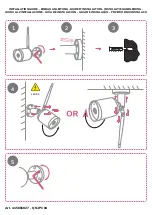
12. Locate the germicidal bulb. DO NOT TOUCH
GLASS ON BULB. Grasp the bulb only by the base
(non-glass part). Clean the bulb using a lint free wipe
and isopropyl alcohol. Make sure O-ring on bulb is
toward the accessory and push into the 1-in. hole until
seated. Hold the bulb in place and lock into place by
installing the spring wire fastener to the lances on the
bulb.
13. Push on the power plug. Do not force. Rotate
90 degrees if necessary.
14. Affix the ultra-violet light warning label to the outside
of the unit, in plain sight, on all access doors. Replace
label when worn. See Fig. 10.
15. Test all circuits and return power to unit. Accessory
bulb should glow with a blue hue. If bulb cannot be
seen briefly back out bulb and view from safe distance.
replace bulb when done. If bulb does not glow, check
wiring, safety interlock, or replace bulb.
Installation (48/50HJ,TJ004-014 Units and
50HJQ004-012 Units) —
Perform the following proce-
dure to install the germicidal lamp:
1. Turn off all power to unit.
2. Install reflective material (field-supplied) in installa-
tion location if desired. Reflecting ultra-violet light
energy is recommended to enhance performance and
reduce shadows. Lining the installation area with alu-
minum or aluminum foil allows light energy to reflect
instead of being absorbed, increasing the effectiveness
of the germicidal lamp.
3. Ultra violet light may damage certain plastics and
exposed non-UVC protected wires. (Drain pans will
not be damaged.) Wrap exposed plastic and wiring
with aluminum tape or use metal conduit.
4. Mount field-provided light-switch disconnect switch
on unit. Disconnect switch should have a waterproof
housing.
Size 004-007 Units:
A field-supplied bracket is required to mount the light-
switch disconnect on size 004-007 units. Perform the
following procedure to install the disconnect switch:
a. Remove two screws from unit top cover flange,
located above accessory installation location. Save
screws.
b. Fabricate disconnect mounting switch bracket. See
Fig. 13 for bracket dimensions and details.
c. Drill hole in side panel of unit for disconnect wir-
ing. See Fig. 14 for hole dimensions.
Be careful not to drill into coil, refrigerant lines, or other
objects inside the HVAC unit. Damage to unit can result.
5.25
16.00
UVC
DISCONNECT
BOX
024-034 UNIT SHOWN
NOTES:
1. Unless otherwise specified all
dimensions are to outside of
part.
2. Dimensions are in inches.
Fig. 11 — Disconnect Switch Location — 48/50EJ,EK,EW,EY Units