24
Evaporator
30XW-VZE/30XWHVZE chillers use a flooded multi-tube
evaporator. The water circulates in the tubes and the refrigerant
is on the outside in the shell. One vessel is used to serve both
refrigerant circuits. There is a center tube sheet which separates
the two refrigerant circuits. The tubes are 3/4” diameter copper
with an enhanced surface inside and out. There is just one water
circuit with two water passes.
The evaporator shell has a polyurethane foam thermal insulation
and a water drain and purge.
It has been tested and stamped in accordance with the applicable
pressure codes. The maximum standard relative operating
pressure is 2100 kPa for the refrigerant side and 1000 kPa for the
water-side. These pressures can be different depending on the
code applied. The water connection of the heat exchanger is a
Victaulic connection.
The products that may be added for thermal insulation of the
containers during the water piping connection procedure must be
chemically neutral in relation to the materials and coatings to which
they are applied. This is also the case for the products originally
supplied by Carrier.
Condenser and oil separator
The 30XW-VZE/30XWHVZE chiller uses a heat exchanger that
is a combination condenser and oil separator. It is mounted below
the evaporator. Discharge gas leaves the compressor and flows
through an external muffler to the oil separator, which is the upper
portion of the heat exchanger. It enters the top of the separator
where oil is removed, and then flows to the bottom portion of the
vessel, where gas is condensed and subcooled. One vessel is
used to serve both refrigerant circuits. There is a center tube sheet
which separates the two refrigerant circuits. The tubes are 3/4” or
1” diameter internally and externally finned copper tubes.
There is just one water circuit with two water passes. For the Heat
Machine units the condenser shell can have a polyure-thane foam
thermal insulation (option 86) and a water drain and purge.
It has been tested and stamped in accordance with applicable
pressure codes. The maximum standard relative operating
pressure is 2100 kPa for the refrigerant side and 1000 kPa for the
water-side. These pressures can be different depending on the
code applied. The water connection of the heat exchanger is a
Victaulic connection.
9.7 - High Pressure SRMCR safety loop
9.7.1 -
General description
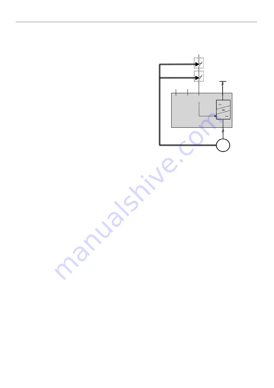
The unit is equipped with a high pressure safety loop, known as
the SRMCR (Safety-Related Measurement Control and
Regulation) loop, comprising
-2 high pressure switches (HPS) that require resetting with a
tool at the outlet for each compressor called PZHH
-The speed regulator which supplies the compressor is
equipped with the Safe Torque Off (STO) function.
Refer to the wiring diagram and the nomenclature for the machine
(references).
This SRMCR device is designed in accordance with standard EN
61508 for SIL (safety integrity level): 2.
Demand mode: bottom and top.
The mission time is 20 years.
Periodic testing: the test must be performed at least once a year
during the normal periodic pressure test. Refer to the description
in section 11.9.
9.7.2 -
Description of operation and resetting
The image below is intended to illustrate the operating description:
refer to the detailed machine drawing for the precise wiring
diagram.
HPS SP_F
Pressure increase
Direction of operation
Pressure increase
Direction of operation
Normal
start-stop
Com bus for
frequency
setting
STO Input
PLd- SIL2
Compressor
06T
HPS SP_F
GS_1 drive
400Vac
HPS :
High pressure switch SP1F(A)/SP2F(A)
GS_1 :
Power drive for compressor GSA1/GSB1
During normal operation, the speed regulator supplies and controls
the compressor once the control signal is received via the digital
on-off input (normal on-off) and the communication bus (setting
the frequency).
When one of the HPS sensors opens, the STO (Safe Torque Off)
digital input opens, which instantly suppresses the control
command for the thyristors which manage the supply for the
compressor, independently of the on-off commands and
frequencies: the compressor is no longer supplied and stops
immediately.
9.7.3 -
Verification in case of a safety device failure
If the unit operating pressure appears to have been exceeded at
some point (for example, after the relief valves have been opened),
the unit must be stopped immediately.
The safety loop unit must pass all the periodic verifications before
any restart is possible.
If the test reveals malfunctions likely to have caused overpressure
within the machine, a complete check of all the pressure equipment
must be performed to check their mechanical integrity.
9.7.4 -
Restarting after high pressure is detected
After overpressure is detected, it is necessary to manually reset
the switched HPS. A blunt tool with a diameter of less than 6 mm
must be used for this.
9 - MAJOR SYSTEM COMPONENTS AND OPERATION DATA


