


73
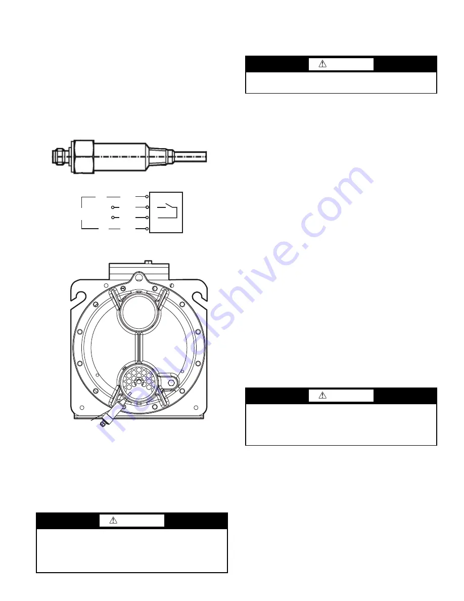
EVAPORATOR CHILLED WATER FLOW SWITCH
A thermal-dispersion flow switch is factory-installed in the en-
tering water nozzle for all machines. See Fig. 70 and 71. Figure
71 shows typical installation. If nuisance trips of the sensor are
occurring, follow the steps below to correct:
1. Check to confirm that all strainers are clean, valves are open
and pumps are running. For the case of VFD-controlled
pumps, ensure the minimum speed setting has not been
changed.
2. Measure the pressure drop across the evaporator. Use the
evaporator pressure drop curves on page 52 to calculate the
flow and compare this to system requirements. The pressure
drop curves are for water only.
Fig. 70 — Chilled Water Flow Switch
Fig. 71 — Flow Switch Location
All Units
EVAPORATOR WATER TREATMENT
Untreated or improperly treated water may result in corrosion,
scaling, erosion or algae. The services of a qualified water
treatment specialist should be obtained to develop and monitor
a treatment program.
PREPARATION FOR WINTER SHUTDOWN
If the unit is not operational during the winter months, at the
end of the cooling season complete the following steps.
Evaporator to be drained for winter shutdown
1. To prepare the system for winter shutdown, draining the flu-
id from the system is highly recommended. Isolate the evap-
orator from the rest of the system with water shutoff valves.
Be sure to deenergize heaters (if installed) by opening circuit
breaker (CB-7) or shut off power to the chiller to prevent
damage if the evaporator is drained.
2. Remove the evaporator drain plug. Follow all local codes
and regulations regarding the fluid disposal.
3. Once fully drained, replace the drain plug(s) and completely
fill the evaporator, and hydronic package if equipped, with
suitable corrosion-inhibited antifreeze solution such as pro-
pylene glycol. The concentration should be adequate to pro-
vide freeze protection to 15°F (8.3°C) below the expected
low ambient temperature conditions. Antifreeze can be add-
ed through the vent on top of the evaporator head. Evapora-
tor fluid volumes can be found in the Installation Instructions
for the unit.
4. Leave the evaporator filled with the antifreeze solution for
the winter to provide corrosion protection during the off
season. The evaporator may be drained if desired. Follow
all local codes and regulations regarding the fluid disposal.
5. At the beginning of the next cooling season, be sure that
there is refrigerant pressure in each circuit before refilling
evaporator, add recommended inhibitor, and reset the circuit
breaker for the heater (CB-7) if opened or restore power.
Evaporator to remain filled for winter shutdown
1. If the evaporator will not be drained, do not shut off power
disconnect during off-season shutdown.
2. If the chilled water loop is not protected with a suitable cor-
rosion-inhibited antifreeze solution such as propylene glycol,
the unit must have evaporator pump control. In the event of a
power failure with sub-freezing temperatures, the unit will
not have any evaporator freeze protection and may be sub-
ject to damage.
3. It is recommended that the loop be protected with a suit-
able corrosion-inhibited antifreeze solution such as pro-
pylene glycol. The concentration should be adequate to
provide freeze protection to 15°F (8.3°C) below the ex-
pected low ambient temperature conditions. Evaporator
heaters will not protect the evaporator from freeze-up in
the event of power loss.
CAUTION
Water must be within design flow limits, clean and treated to
ensure proper machine performance and reduce the potential
of tubing damage due to corrosion, scaling, and algae. Carrier
assumes no responsibility for evaporator damage resulting
from untreated or improperly treated water.
24 VAC
N
L1
BRN
WHT
BLK
BLU
1
2
3
4
OUT
IN
FLOW
S
WITCH
(NOT TO
S
CALE)
a30-5854
CAUTION
Failure to remove power before draining heater equipped
evaporators can result in heater damage.
CAUTION
Operation or winter shutdown with fresh water is not fail-
safe should there be a loss of power to the chiller or to the
circulating pump. Freeze damage due to power loss or dis-
abling chiller pump control in fresh water systems will im-
pair or otherwise negatively affect the warranty.
Содержание AquaForce 30XV140
Страница 79: ...79 Fig 76 VFD Communication Wiring Compressor A B Fan VFD A1 A2 B1 B2...
Страница 82: ...82 Fig 81 VFD Compressor Locations 30XV225 325 30XV350 500 30XV140 325 COMPRESSOR A VFD COMPRESSOR B VFD...
Страница 228: ...228 Fig 90 30XV Typical Field Wiring Schematic cont...
Страница 229: ...229 Fig 91 30XV Standard Tier 140 275 All Voltages Power Schematic NOTE See Legend on page 226...
Страница 230: ...230 Fig 92 30XV Standard Tier 300 325 All Voltages Power Schematic NOTE See Legend on page 226...
Страница 231: ...231 Fig 92 30XV Standard Tier 300 325 All Voltages Power Schematic cont NOTE See Legend on page 226...
Страница 232: ...232 Fig 93 30XV Standard Tier 350 500 380 400 415 440 460 575v Power Schematic NOTE See Legend on page 226...
Страница 233: ...233 Fig 93 30XV Standard Tier 350 500 380 400 415 440 460 575v Power Schematic cont NOTE See Legend on page 226...
Страница 234: ...234 Fig 94 30XV High Tier 350 450 All Voltages Mid Tier 350 500 All Voltages Power Schematic NOTE See Legend on page 226...
Страница 235: ...235 Fig 95 30XV Mid Tier 140 All Voltages 160 275 380 400 415 440 460 575v Power Schematic NOTE See Legend on page 226...
Страница 236: ...236 Fig 96 30XV High Tier 140 200 380 400 415 440 460 575v Power Schematic NOTE See Legend on page 226...
Страница 237: ...237 Fig 97 30XV High Tier 140 200 208 230v Mid Tier 160 200 208 230v Power Schematic NOTE See Legend on page 226...
Страница 238: ...238 Fig 98 30XV High Tier 225 325 All Voltages Mid Tier 300 325 All Voltages Power Schematic NOTE See Legend on page 226...
Страница 240: ...240 Fig 99 30XV Communication Wiring...
Страница 241: ...241 Fig 100 30XV 115V Control Wiring All Tonnages All Voltages...
Страница 242: ...242 Fig 101 30XV 24V Control Wiring 30XV140 325 All Voltages...
Страница 243: ...243 Fig 101 30XV 24V Control Wiring 30XV140 325 All Voltages cont...
Страница 244: ...244 Fig 102 30XV 24V Control Wiring 30XV350 500 All Voltages...
Страница 245: ...245 Fig 102 30XV 24V Control Wiring 30XV350 500 All Voltages cont...
Страница 246: ...246 Fig 103 Component Arrangement Diagram for 30XV140 325...
Страница 247: ...247 Fig 103 Component Arrangement Diagram for 30XV140 325 cont...
Страница 248: ...248 Fig 104 Component Arrangement Diagram for 30XV350 500...
Страница 337: ...337 APPENDIX J FACTORY SUPPLIED PUMPS cont Fig L System Information...
Страница 338: ...338 APPENDIX J FACTORY SUPPLIED PUMPS cont Fig M Unit and Language Settings...
Страница 339: ...339 APPENDIX J FACTORY SUPPLIED PUMPS cont Fig N Hand Off Auto This is set in Auto mode for sensorless operation...
Страница 341: ...341 APPENDIX J FACTORY SUPPLIED PUMPS cont Fig P Data Input 2...
Страница 342: ...342 APPENDIX J FACTORY SUPPLIED PUMPS cont Fig Q Data Input 3...
Страница 347: ...347 APPENDIX J FACTORY SUPPLIED PUMPS cont Fig U Pump Wiring Diagram...


