


59
APPENDIX D — REMOTE CONNECTIVITY SETUP
(BY CARRIER SERVICE)
Introduction
Cellular Remote Connectivity is a system developed by Carrier
to remotely monitor a chiller. It consists of a PIC6 controller,
ethernet switch, cellular modem, and an antenna. The option is
included standard with all applied 19 Series equipment. For a
new chiller there is a free period of operation with remote con-
nectivity after commissioning. Attached documentation is based
on use of Sierra wireless router/modem. This appendix describes
typical commissioning steps required for a chiller supplied with
the Remote Connectivity option. For support or when completed
contact the Command Center at 1-833-257-6280 or email at
[email protected]. Typical component interactions are
shown in Fig. D.
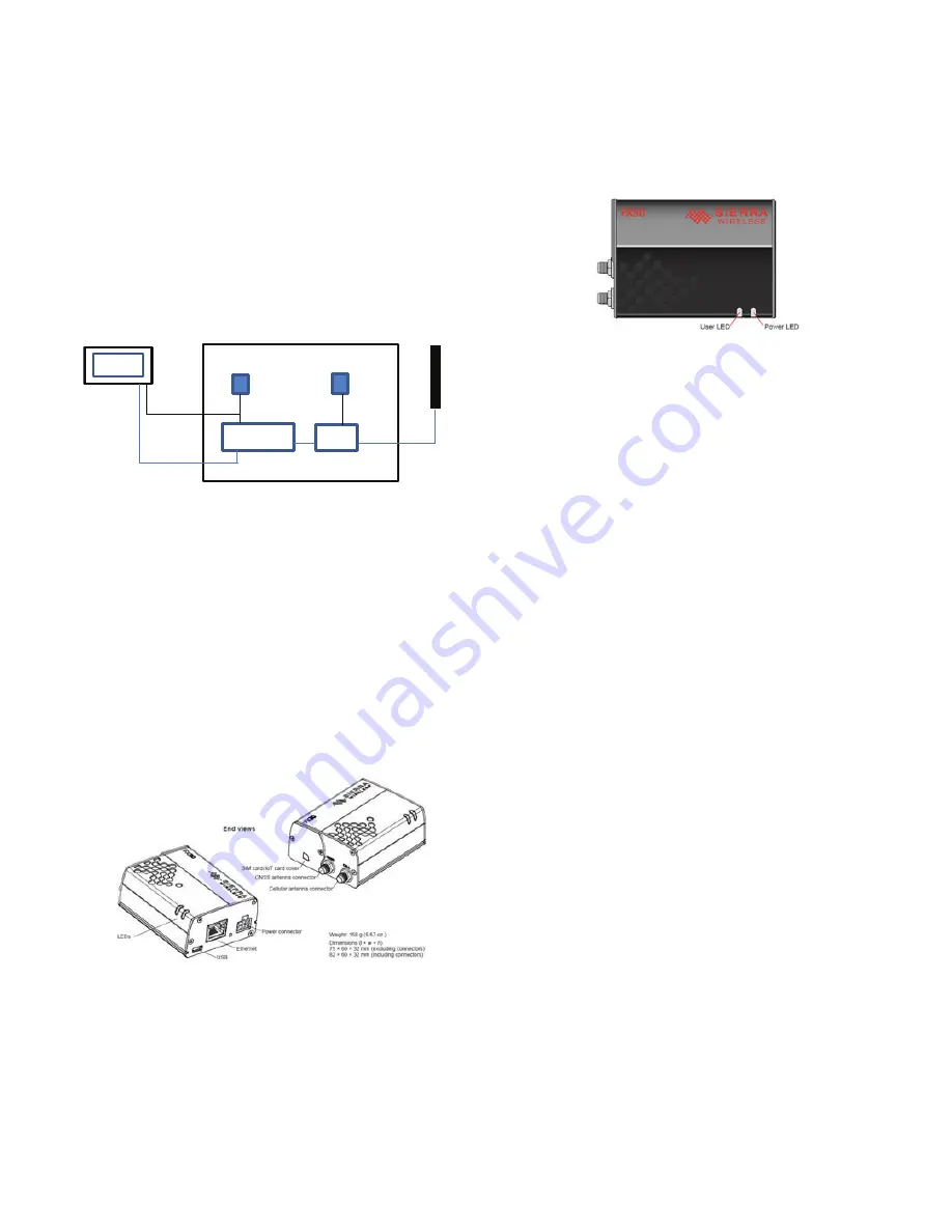
Fig. D — Remote Connectivity
Verification and Testing
First locate the cellular antenna which is located in the chiller con-
trol/power panel. This component is not installed at the factory
since optimum mounting location is needed to be identified at the
site as part of Remote Connectivity commissioning.
Next, identify the location of the router and ethernet switch in the
power panel. There will typically be hazardous voltage in the con-
trol panel where the remote connectivity hardware pieces are in-
stalled. Therefore make all connections prior to connecting power
to the chiller as otherwise it is required to wear appropriate PPE to
protect against arch flash potential and other electrical hazards.
1. Verify that PIC6 is connected via ethernet to the ethernet
switch.
2. Verify that antenna is installed to cellular antenna connection.
Fig. E — End Views of Remote Connectivity
Hardware
3. Verify that a SIM card is installed (before power up).
4. Modem powers up when power is applied to chiller. The
Power LED will be off when there is no power applied. The
Power LED will be solid red when power is on and there is
no cellular signal and solid green when attached to a cellular
network. The User LED is not used. See Fig. F.
5. Navigate to PIC6 System Configuration
Ethernet Con-
figuration and record the PIC6 MAC address of ETH0
(example 52:CC:00:02:11:C4).
6. Default ethernet IP address for the Sierra modem is
169.254.1.2. Set the interface for the PIC6 ethernet port
which is going to be used to 169.254.101 for the first chiller
and if multiple chillers increase last digit by one for each
chiller. APPLY the setting in the PIC6 menu. Up to a total of
5 chillers can be installed to one modem (if required).
Fig. F — User LED and Power LED
7. For the PIC6 ethernet port which is going to be used
ensure that Subnet mask is 255.255.0.0.
8. Navigate to the PIC6 System Configuration
Gateway/
DNS Config menu. Set Gateway 0 IP to 169.254.1.2 and
Gateway Destination/Mask to 0.0.0.0/0 and APPLY the
changes.
NOTE: Gateway 1 is generally not used in SmartService
applications. However, presently you must set Gateway 1 to
the same settings as Gateway 0 and apply the settings.
9. Set DNS Servers to 169.254.1.2 and APPLY the change;
the status should show “DNS applied successfully”.
10. Test connectivity (PIC6 System Configuration
Network
Diagnostic:
a. Run ping test to modem: Enter 169.254.1.2 into Server
Address and select appropriate ethernet port. Then select
“Run PING test”. If the PIC6 can connect to the modem
the PIC6 will display “In Progress” followed by “Pass”.
b. Run ping test to internet: Enter 8.8.8.8 into Serve
Address and select appropriate ethernet port. Then select
“Run PING test”. If the PIC6 can connect to the modem
the PIC6 will display “In Progress” followed by “Pass”.
c. Run could test to SmartService cloud. Note that if previ-
ous ping test has failed then this test will also fail. In
addition verify on the PIC6 Network Diagnostic page
that “IOT certificate status: Present” is noted near top of
page. If the IOB certificate is not present, then it will
have to be loaded. Contact Service Engineering or Tech-
nical Service Manager.
11. Verify Time, Date and Time Zone. PIC6 System Configu-
ration
Date/Time Configuration.
Connect to SmartService
Upon successful completion, contact the Command Center at
1-833-257-6280 or email [email protected]. The Com-
mand Center will set up the chillers in CarrierSmart or see if they
are already onboarded properly.
When contacting the Command Center please have the following
information available:
Jobsite Information:
• Street Address, City, State and Zip code
• CCS Office
• CCS Market
• Carrier Job number or Contract number
Chiller data (for each chiller being onboarded):
• Job site Designation (e.g Chiller 1 or alike used to identify
the chiller at the job site)
• Model Number
• Full Serial Number
• Eth0 MAC Address
SIERRA
ROUTER
ETHERNET
SWITCH
DC
POWER
AC
POWER
ANTENNA
PIC6
POWER PANEL
Содержание AquaEdge 19MV
Страница 49: ...49 Fig 46 SIOB...
Страница 50: ...50 Fig 47 IOB2...
Страница 51: ...51 Fig 48 19MV Auxiliary Controls Wiring...
Страница 52: ...52 Fig 49 Motor Bearing Control Board Wiring...


