


6
−
2
T
−
318
6.3 SERVICE VALVES
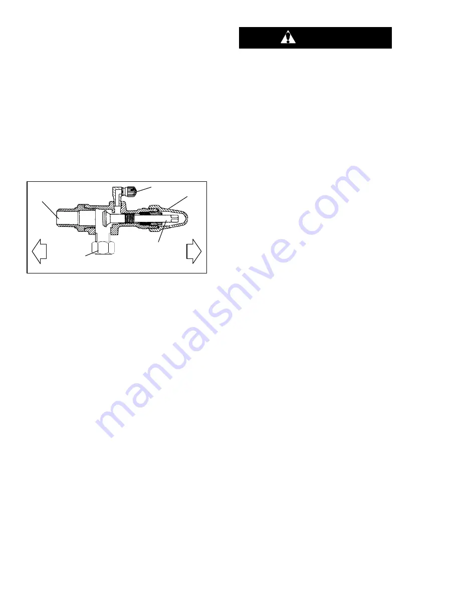
Compressor suction, compressor discharge, and liquid
line service valves (see Figure 6-3) are provided with a
double seat and a gauge connection, which enables
servicing of the compressor and refrigerant lines.
Turning the valve stem clockwise (all the way forward)
will frontseat the valve to close off the suction, discharge
or liquid line and open the gauge port to the compressor
or low side. Turning the stem counterclockwise (all the
way out) will backseat the valve to open the connections
and close off the port
With the valve stem midway between frontseat and
backseat, both of the service valve connections are
open to the access valve path.
For example, the valve stem is first fully backseated
when connecting a manifold gauge to measure
pressure. Then, the valve is opened 1/4 to 1/2
−
turn to
measure the pressure.
1. Line Connection
2. Access Valve
3. Stem Cap
4. Valve stem
5. Compressor Or Filter
Drier Inlet Connection
6. Valve (Frontseated)
7. Valve (Backseated)
Figure 6-3 Service Valve
Connection of the manifold gauge/hose set (see
Figure 6-4) is dependent on the component being
serviced. If only the compressor is being serviced, the
high side coupling is connected to the discharge service
valve.
For service of the low side (after pump down), the high
side coupling is connected to the liquid line service
valve. The center hose connection is brought to the tool
being used (vacuum, tank, etc.).
Connecting the manifold gauge set:
a. Remove service valve stem cap and make sure the
valve is backseated.
b. Remove service port cap (See Figure 6-3).
c. Connect the high side field service coupling (see
Figure 6-2) to the discharge or liquid line valve ser-
vice valve port.
d. Turn the high side field service coupling knob (red)
clockwise, which will open the high side of the sys-
tem to the gauge set.
e. Connect the low side field service coupling to the
suction service valve port.
f. Turn the low side field service coupling knob (blue)
clockwise, which will open the low side of the system
to the gauge set.
g. To read system pressures, slightly midseat the high
side and suction service valves.
CAUTION
To prevent trapping liquid refrigerant in the
manifold gauge set, be sure set is brought
to suction pressure before disconnecting.
Removing the Manifold Gauge Set:
a. While the compressor is still ON, backseat the high
side service valve.
b. Midseat both hand valves on the manifold gauge set
and allow the pressure in the manifold gauge set to
be drawn down to suction pressure. This returns any
liquid that may be in the high side hose to the system.
c. Backseat the suction service valve. Backseat both
field service couplings and frontseat both manifold
set valves. Remove the couplings from the service
ports.
d. Install both service valve stem caps and service port
caps (finger-tight only).
6.4 PUMP THE UNIT DOWN
To service the filter-drier, moisture-liquid indicator,
expansion valve, suction modulation valve, quench
valve, or evaporator coil, pump the refrigerant into the
high side as follows:
a. Attach manifold gauge set to compressor service
valves (refer to paragraph 6.2).
b. Start the unit and run in a cooling mode for 10 to 15
minutes. Frontseat the liquid line service valve. Place
start-stop switch in the OFF position when the suction
reaches a positive pressure of 0.1kg/cm
(1.0psig).
c. Frontseat the suction service valve. The refrigerant
will be trapped between the compressor suction ser-
vice valve and the liquid line valve.
d. Before opening up any part of the system, a slight
positive pressure should be indicated on the pressure
gauge. If a vacuum is indicated, emit refrigerant by
cracking the liquid line valve momentarily to build up a
slight positive pressure.
e. When opening up the refrigerant system, certain
parts may frost. Allow the part to warm to ambient
temperature before dismantling. This avoids internal
condensation, which puts moisture in the system.
f. After repairs have been made, be sure to perform a
refrigerant leak check (refer to paragraph 6.5), and
evacuate and dehydrate the low side (refer to
paragraph 6.6).
Содержание 69NT40-541-300
Страница 2: ......
Страница 4: ......
Страница 20: ......
Страница 32: ......
Страница 128: ......
Страница 131: ...7 3 T 318 Based on Drawing 62 66058 Figure 7 2 SCHEMATIC DIAGRAM Units with 3 Phase Evaporator Motors...
Страница 133: ...7 5 T 318 6 Heater FCCH FCCH Figure 7 4 SCHEMATIC DIAGRAM Units with Normal Evaporator Fan Capability...
Страница 134: ...7 6 T 318 FCCH FCCH Figure 7 5 SCHEMATIC DIAGRAM Units with Single Evaporator Fan Capability...
Страница 136: ...7 8 T 318 To ST10 To TRX2 To QC1 To QC1 To QC1 To MC6 CONTROLLER Figure 7 7 SCHEMATIC DIAGRAM Emergency Bypass...
Страница 138: ...7 10 T 318 Based on Drawing 62 66058 Figure 7 9 UNIT WIRING DIAGRAM Units with 3 Phase Evaporator Motors Sheet 1 of 2...
Страница 139: ...7 11 T 318 Based on Drawing 62 66058 Figure 7 10 UNIT WIRING DIAGRAM Units with 3 Phase Evaporator Motors Sheet 2 of 2...
Страница 144: ......
Страница 150: ......
Страница 151: ......