


40
To use the keypad when working with menus:
• Press the ▲ (Up arrow) button to move to the previous
menu.
• Press the ▼ (Down arrow) button to move to the next
menu.
• Press the
(Enter) button to display the first item in the
currently displayed menu.
• Press the
(Menu Up/Exit) button to exit a menu’s item
and return to the list of menus.
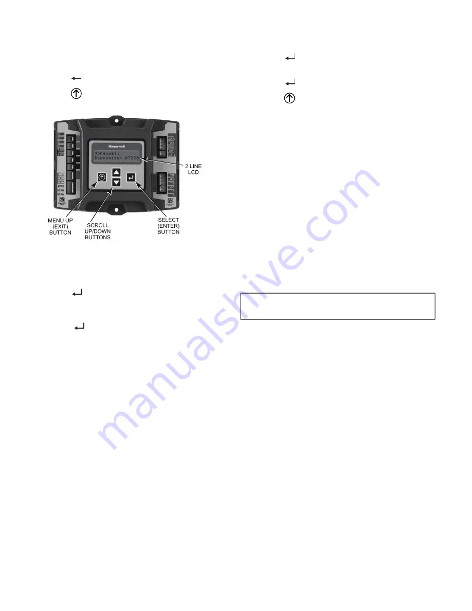
Fig. 50 — W7220 Controller Navigation Buttons
To use the keypad when working with Setpoints, System and
Advanced Settings, Checkout tests and Alarms:
1. Navigate to the desired menu.
2. Press the
(Enter) button to display the first item in the
currently displayed menu.
3. Use the ▲ and ▼ buttons to scroll to the desired
parameter.
4. Press the
(Enter) button to display the value of the
currently displayed item.
5. Press the ▲ button to increase (change) the displayed
parameter value.
6. Press the ▼ button to decrease (change) the displayed
parameter value.
NOTE: When values are displayed, pressing and holding the
▲ or ▼ button causes the display to automatically increment or
decrement.
1. Press the
(Enter) button to accept the displayed value
and store it in nonvolatile RAM. “CHANGE STORED”
displays.
2. Press the
(Enter) button to return to the current menu
parameter.
3. Press the
(Menu Up/Exit) button to return to the previ
-
ous menu.
Menu Structure
Table 21 illustrates the complete hierarchy of menus and pa
-
rameters for the EconoMi$er
®
X system.
The Menus in display order are:
• STATUS
• SETPOINTS
• SYSTEM SETUP
• ADVANCED SETUP
• CHECKOUT
• ALARMS
NOTE: Some parameters in the menus use the letters MA or
MAT, indicating a mixed air temperature sensor location before
the cooling coil. This unit application has the control sensor locat
-
ed after the cooling coil, in the fan section, where it is designated
as (Cooling) Supply Air Temperature or SAT sensor.
SETUP AND CONFIGURATION
Before being placed into service, the W7220 economizer mod
-
ule must be set up and configured for the installed system.
The setup process uses a hierarchical menu structure that is
easy to use. Press the ▲ and ▼ arrow buttons to move forward
and backward through the menus and press the button to select
and confirm setup item changes.
Time-Out and Screensaver
When no buttons have been pressed for 10 minutes, the LCD
displays a screen saver, which cycles through the Status items.
Each Status items displays in turn and cycles to the next item
after 5 seconds.
IMPORTANT: During setup, the economizer module is
live at all times.
Содержание 48LC 14
Страница 27: ...27 Fig 38 Integrated Gas Control IGC Board RED LED STATUS...
Страница 81: ...81 Fig B Typical Electromechanical Control Wiring Diagram 48LC 14 26 APPENDIX D WIRING DIAGRAMS...
Страница 82: ...82 Fig C 48LC 14 26 Systemvu Control Schematic APPENDIX D WIRING DIAGRAMS...
Страница 83: ...83 Fig D 48LC 14 26 RTU Open Control Wiring Diagram APPENDIX D WIRING DIAGRAMS...
Страница 85: ......


