


14
Compressors
LUBRICATION
Compressors are charged with the correct amount of oil at the
factory.
REPLACING COMPRESSOR
The compressor used with Puron refrigerant contains a POE oil.
This oil has a high affinity for moisture. Do not remove the com
-
pressor’s tube plugs until ready to insert the unit suction and dis
-
charge tube ends.
1. Remove all sources of power to the unit. Install lock-out tag.
2. Recover refrigerant using environmentally friendly
procedures.
3. Remove electrical wires from compressor terminal. Caution
must be used when removing wires from compressor termi
-
nals. Use pliers, gloves, safety glasses and do not face
directly towards the compressor terminals. Terminal blow
out could occur.
4. With refrigerant completely recovered, open both sides of
manifold gage set. Refrigerant system should now be at
ambient pressures.
5. Prior to applying heat and removing compressor, procure a
wet quenching cloth and fire extinguisher.
6. Using torch, heat compressor discharge line and remove hot
gas tube from compressor.
7. Using torch, heat compressor suction line and remove suction
tube from compressor.
8. Remove system filter drier and replace with new.
9. Loosen four compressor retaining bolts and save components
for installation of new compressor.
10. Using proper lifting techniques or devices, remove compres
-
sor from system.
Compressor mounting bolt torque is 65 to 75 in-lb (7.3 to
8.5 Nm).
COMPRESSOR ROTATION
On 3-phase units with scroll compressors, it is important to be cer
-
tain compressor is rotating in the proper direction. To determine
whether or not compressor is rotating in the proper direction:
1. Connect service gages to suction and discharge pressure
fittings.
2. Energize the compressor.
3. The suction pressure should drop and the discharge pressure
should rise, as is normal on any start-up.
NOTE: If the suction pressure does not drop and the discharge
pressure does not rise to normal levels:
4. Note that the evaporator fan is probably also rotating in the
wrong direction.
5. Turn off power to the unit.
6. Reverse any two of the unit power leads.
7. Reapply power to the compressor.
The suction and discharge pressure levels should now move to
their normal start-up levels.
NOTE: When the compressor is rotating in the wrong direction,
the unit makes an elevated level of noise and does not provide
cooling.
Filter Drier
Replace whenever refrigerant system is exposed to atmosphere.
Only use factory specified liquid-line filter driers with working
pressures no less than 650 psig. Do not install a suction-line filter
drier in liquid line. A liquid-line filter drier designed for use with
Puron (R-410A) refrigerant is required on every unit.
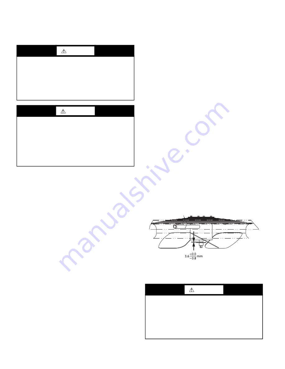
Condenser-Fan Adjustment
1. Shut off unit power supply. Install lockout tag.
2. Remove condenser-fan assembly (grille, motor, and fan).
3. Loosen fan hub setscrews.
4. Adjust fan height as shown in Fig. 14.
5. Tighten setscrews to 84 in-lb (9.5 Nm).
6. Replace condenser-fan assembly.
Fig. 14 — Condenser Fan Adjustment
CONVENIENCE OUTLETS
CAUTION
UNIT DAMAGE HAZARD
Failure to follow this caution may result in damage to
components.
The compressor is in a R-410A refrigerant system and uses a
polyolester (POE) oil. This oil is extremely hygroscopic,
meaning it absorbs water readily. POE oils can absorb
15 times as much water as other oils designed for HCFC and
CFC refrigerants. Avoid exposure of the oil to the atmosphere.
WARNING
PERSONAL INJURY AND ENVIRONMENTAL
HAZARD
Failure to follow this warning could cause personal injury or
death.
Relieve pressure and recover all refrigerant before system re
-
pair or final unit disposal.
Wear safety glasses and gloves when handling refrigerants.
Keep torches and other ignition sources away from refriger
-
ants and oils.
WARNING
ELECTRICAL OPERATION HAZARD
Failure to follow this warning could result in personal injury or
death.
Units with convenience outlet circuits may use multiple
disconnects. Check convenience outlet for power status before
opening unit for service. Locate its disconnect switch, if
appropriate, and open it. Lock-out and tag-out this switch, if
necessary.
Содержание 48LC 14
Страница 27: ...27 Fig 38 Integrated Gas Control IGC Board RED LED STATUS...
Страница 81: ...81 Fig B Typical Electromechanical Control Wiring Diagram 48LC 14 26 APPENDIX D WIRING DIAGRAMS...
Страница 82: ...82 Fig C 48LC 14 26 Systemvu Control Schematic APPENDIX D WIRING DIAGRAMS...
Страница 83: ...83 Fig D 48LC 14 26 RTU Open Control Wiring Diagram APPENDIX D WIRING DIAGRAMS...
Страница 85: ......


