6
START-UP
Preliminary Inspection
1. Disconnect power to unit. Use safety lockouts and label
all disconnects to prevent unintentional powering.
2. Verify all field connections and wiring meet applicable
codes. Verify that power supply connection voltage
matches nameplate rating. Verify all wiring terminals are
tight.
3. Inspect all piping for leak and verify conformance to pip-
ing codes.
4. Remove all fan shipping tie-downs and bracing. See the
section Fan Start-Up below.
5. Verify required filters are securely in place before starting
unit.
6. Verify supply duct(s) are free from obstructions.
7. Verify all supply dampers/diffusers area open.
Fan Start-Up
1. Inspect fan and drive assembly (see Fig. 10). Adjust belt
(if applicable) to appropriate tension and alignment.
2. Check fan rotation. Correct by changing wiring if re-
quired.
3. Power the fan, measure airflow per AMCA (Air Move-
ment and Control Association) suggested methods, and
compare to nameplate data. Adjust either the VFD (vari-
able frequency drive) or belt-drive sheave to alter the fan
speed to achieve required flow.
4. After proper flow is achieved, verify that the motor amp
draw agrees with the motor nameplate full load amp
rating.
SERVICE
Monthly
1. Check supply air filters and clean or replace as required.
2. Check the cooling coil condensate drain pan for proper
draining and clean if necessary.
3. Fan bearings with grease fittings need to be lubricated.
Bearings that do not have grease fittings are permanently
sealed and do not require lubrication. Check submittal
data for types of bearings used.
a. Fans ship from the factory with fan bearings fac-
tory-lubricated. The fan should be turned off and
locked out to prevent accidental start-up during
lubrication.
b. Verify that the sheaves are secured before servic-
ing the fan.
c. Generally, lubricate fan bearings every 1000 hours.
d. Add grease with manual grease gun until a light
bead of grease appears at the bearing grease seal.
Alternatively, the grease capacity recommenda-
tions in Tables 1 and 2 can help for proper grease
charge.
e. Always lubricate bearings prior to extended shut-
down or storage and rotate shaft monthly.
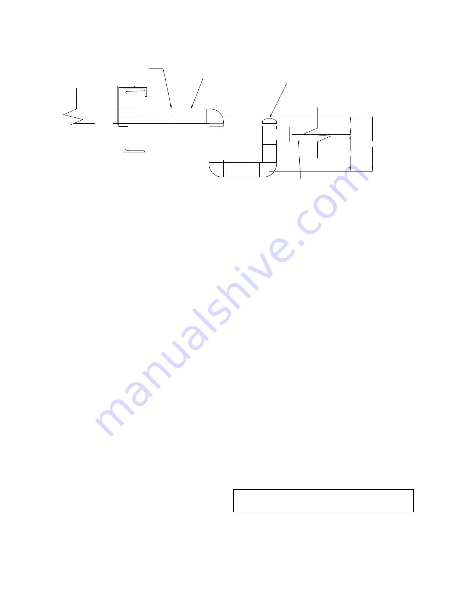
1-¼ IN. MP
SLOPE
IN. PER FT MIN.
1
/
8
CLEAN OUT
SLOPE
IN. PER FT MIN.
1
/
8
A
B
C
a39-4468
(+) STATIC PRESSURE
(BLOW THROUGH COIL)
A
—
1 in.
B
—
TSP + 1 in.
C
TSP + 2 in.
(-) STATIC PRESSURE
(DRAW THROUGH COIL)
A
—
TSP + 1 in.
B
—
1
/
2
TSP + 1 in.
C
1-
1
/
2
TSP + 2 in.
LEGEND
MP
—
Male Pipe
TSP
—
Total Static Pressure (inside drain plenum,
in inches of water)
Fig. 9 — Condensate Drain Trap Sizing
IMPORTANT: Use only lithium-based grease. See the


