


10
OPERATION
To use the Navigator™ module, plug the RJ14 connector
into the LEN port. On power up, the Navigator module
displays:
ComfortLink
Navigator
By
Carrier
The Navigator module will upload the appropriate display
tables from the Main Base Board (MBB) that it is connected to.
A ‘Communication failure’ message will be displayed if any
errors are encountered. Check the wiring at the connector and
the MBB-J5 plug if necessary. After successful upload of
information, the Navigator module begins its default display.
An example of the display in the default mode is:
EWT
54.2 °F
ENTERING FLUID TEMP
The entire local display command structure can be accessed
with the Navigator module. Pressing any key while in the de-
fault display mode will cause the Navigator module to enter its
manual mode. In this mode, all sub-modes and items of the
local display command structure, denoted on the display
screen, can be accessed. The Navigator module automatically
returns to the default display mode after 60 seconds of no
keypad activity. Pressing the
and
keys
simultaneously while the unit displays “Select a menu item”
will also return the device to its default display mode.
Navigating through Menu Structures —
The ar-
row keys are used to scroll through the tiered command menu
structure. See the base unit Controls, Start-Up, Operation, and
Service Guide for menu structure. The
key is used to
select a menu item or to accept data entry. The
key
is used to exit to the next highest command level (mode) or to
cancel data entry. The sub-mode and item displays will wrap
around with the last and first items separated by a line of dashes
on the display. The ‘>’ symbol is the pointer and is located at
the left side of the display.
At any time, press the
key repeatedly as needed
to display “Select a menu item” on the screen. This is the top
level and the arrow keys are used to move the red LED to one
of the 11 desired modes. Press
to display the sub-
modes within a top level mode.
Use the arrow keys to move the pointer (‘>’) to the desired
sub-mode. Up to four sub-modes will be displayed on the
Navigator module at one time. Continue pressing the arrow
keys as needed to find the desired sub-mode.
ENTER
ESCAPE
ENTER
ESCAPE
ESCAPE
ENTER
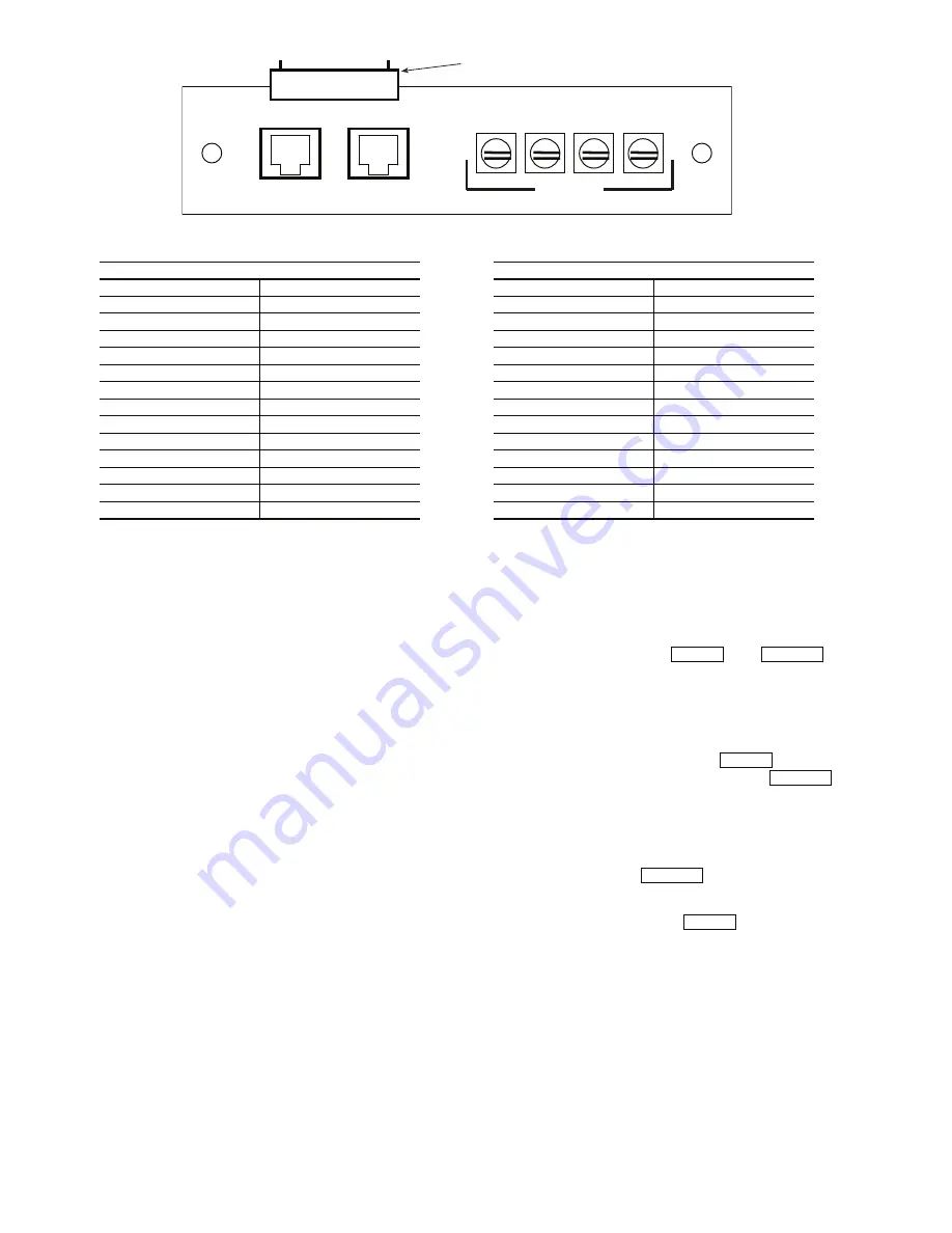
CCN
CCN
LEN
(+)
(-)
(COM)
S
HIELD
1
8
PLUG TERMINAL
TERMINAL BLOCK DETAIL
Fig. 9 — Communication Board Detail
30 Series Chillers (HK,HL,HW,RB)
Packaged Rooftop Units (PG,A,Z)
PLUG TERMINAL
TRACE TO
PLUG TERMINAL
TRACE TO
PIN 1
LEN PLUG, PIN 2
PIN 1
CCN SCREW ‘-’
PIN 2
LEN PLUG, PIN 3
PIN 1
CCN PLUG, PIN 5
PIN 3
LEN PLUG, PIN 5
PIN 2
CCN SCREW ‘COM’
PIN 4
LEN PLUG, PIN 1
PIN 2
CCN PLUG, PIN 3’
PIN 4
CCN PLUG, PIN 1
PIN 3
CCN SCREW ‘+’
PIN 5
LEN PLUG, PIN 6
PIN 3
CCN PLUG, PIN 2
PIN 5
CCN PLUG, PIN 6
PIN 4
CCN PLUG, PIN 6
PIN 6
CCN PLUG, PIN 5
PIN 4
LEN PLUG, PIN 6
PIN 6
CCN SCREW ‘-’
PIN 5
CCN PLUG, PIN 1
PIN 7
CCN PLUG, PIN 3’
PIN 5
LEN PLUG, PIN 1
PIN 7
CCN SCREW ‘COM’
PIN 6
LEN PLUG, PIN 5
PIN 8
CCN PLUG, PIN 2
PIN 7
LEN PLUG, PIN 3
PIN 8
CCN SCREW ‘+’
PIN 8
LEN PLUG, PIN 2
a30-4464
Содержание 30GT-911---062
Страница 6: ...6 NAVIGATOR LEN CONNECTION CCN Fig 5 30RB130 300 Units Navigator LEN Connection a30 4463...
Страница 7: ...7 NAVIGATOR LEN CONNECTION CCN Fig 6 Typical 48 50PG Series Navigator LEN Connection a48 8278...
Страница 9: ...9 NAVIGATOR LEN CONNECTION CCN Fig 8 Typical 48 50Z Series Navigator LEN Connection a48 8280...


