22
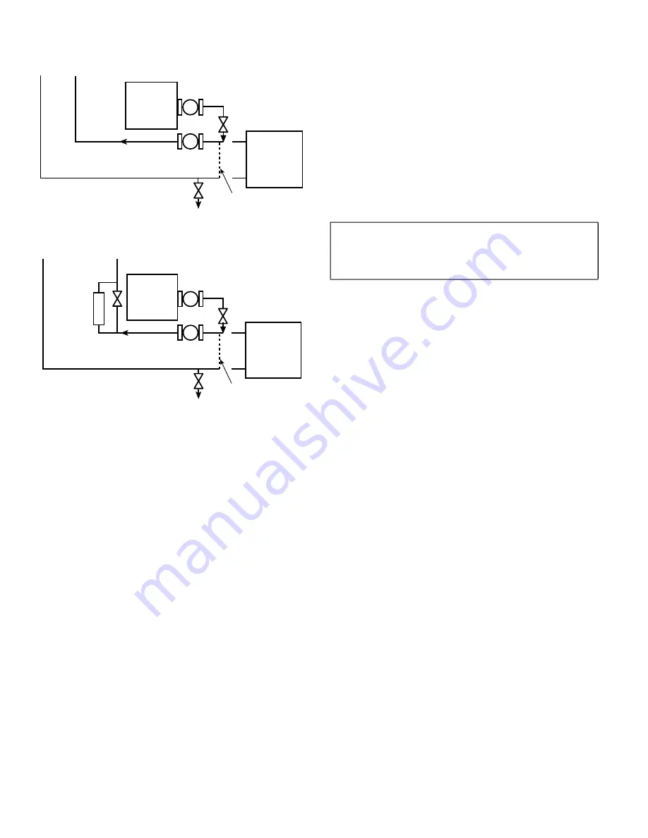
Also, be sure that there is capability to fully drain the system
after cleaning. (See Fig. 23 and 24.)
Fig. 23 —
Typical Set-up for Cleaning Process
Fig. 24 —
Cleaning Process Using Side Stream Filter
2. Be sure to use a cleaning agent that is compatible with all sys
-
tem materials. Be especially careful if the system contains
any galvanized or aluminum components. Both detergent-
dispersant and alkaline-dispersant cleaning agents are avail
-
able.
3. It is a good idea to fill the system through a water meter. This
provides a reference point for the future for loop volume
readings, and it also establishes the correct quantity of cleaner
needed in order to get the required concentration.
4. Use a feeder/transfer pump to mix the solution and fill the
system. Circulate the cleaning system for the length of time
recommended by the cleaning agent manufacturer.
a. After cleaning, drain the cleaning fluid and flush the sys
-
tem with fresh water.
b. A slight amount of cleaning residue in the system can
help keep the desired, slightly alkaline, water pH of 8 to
9. Avoid a pH greater than 10, since this will adversely
affect pump seal components.
c. A side stream filter is recommended (see Fig. 24) during
the cleaning process. Filter side flow rate should be
enough to filter the entire water volume every 3 to 4
hours. Change filters as often as necessary during the
cleaning process.
d. Remove temporary bypass when cleaning is complete.
Properly installed and cleaned systems will rarely need the
strainer cleaned after the initial fill. This time interval is user-
configurable.
WATER TREATMENT
Fill the fluid loop with an inhibited antifreeze solution suitable for
the water of the area. The solution concentration must be sufficient
to protect the chilled water loop to a freeze protection (first crys
-
tals) concentration of at least 15°F (8.3°C) below the lowest de
-
sign ambient temperature. Consult the local water treatment spe
-
cialist for characteristics of system water and a recommended in
-
hibitor for the fluid loop.
Untreated or improperly treated fluid may result in corrosion, scal
-
ing, erosion, or algae. The services of a qualified water treatment
specialist should be obtained to develop and monitor a treatment
program.
FILLING THE SYSTEM
In areas where the piping or unit is exposed to 32°F (0°C) or lower
ambient temperatures, freeze-up protection is required using in
-
hibited glycol or other suitable, heat exchanger rated, corrosion-re
-
sistant antifreeze solution. Heater tapes cannot be installed on the
coils and heater tape on piping will not provide any protection.
NOTE: Do not use automobile antifreeze, or any other fluid that is
not approved for heat exchanger duty. Only use appropriately in
-
hibited glycols, concentrated to provide adequate protection for
the temperature considered.
If the unit is in operation year-round, add sufficient suitable inhib
-
ited antifreeze solution such as propylene or ethylene glycol to
chilled water to prevent freezing under low-ambient temperature
operating conditions. Consult a local water treatment specialist on
characteristics of water and recommended inhibitor.
The initial fill of the fluid system must accomplish three purposes:
• The entire piping system must be filled with water/anti
-
freeze solution.
• The pressure at the top of the system must be high enough
to vent air from the system (usually 4 psig [28 kPa] is ade
-
quate for most vents).
• The pressure at all points in the system must be high
enough to prevent flashing in the piping or cavitation in
the pump.
Ensure the following when filling the system:
1. Remove temporary bypass piping and cleaning/flushing
equipment.
2. Check to make sure all drain plugs are installed.
3. Vents (if installed) at the top of the coils should be open.
4. Open the blow-down valve to flush the strainer.
5. Check for fluid leaks and repair as necessary.
Normally, a closed system needs to be filled only once. The actual
filling process is generally a fairly simple procedure. All air
should be purged or vented from the system. Thorough venting at
the high points at the top of all coils and circulation at room tem
-
perature for several hours is recommended.
NOTE: Local codes concerning backflow devices and other pro
-
tection of the city water system should be consulted and followed
to prevent contamination of the public water supply. This is espe
-
cially important when antifreeze is used in the system.
SET WATER FLOW RATE
Once the system is cleaned, pressurized, and filled, the flow
rate must be set. Set the flow rate per the chiller instructions.
The chiller flow is critical for correct performance and reliabil
-
ity. The 09FC is less sensitive to off design flow rates. Flow
-
rate should be set with the 09FC unit in free cooling mode.
This mode will have a larger pressure drop than the bypass
mode. Setting the flow in this mode assures the chiller will al
-
ways have the minimum flow required for operation.
x
x
DILUTED
CLEANING
AGENT
SYSTEM
POT FEEDER AND
TRANSFER PUMP
UNIT
TO DRAIN
TEMPORARY
PUMP
TEMPORARY
BYPASS
x
x
DILUTED
CLEANING
AGENT
SYSTEM
SIDE
STREAM
FILTER
POT FEEDER AND
TRANSFER PUMP
UNIT
TO DRAIN
TEMPORARY
PUMP
TEMPORARY
BYPASS
IMPORTANT: Adding antifreeze solution is the only cer
-
tain means of protecting the unit from freeze-up since heat
-
ers cannot protect the coils while temperatures are below
32°F (0°C).
Содержание 09FC020
Страница 8: ...8 Fig 5 09FC 020 Unit Dimensions...
Страница 9: ...9 Fig 6 09FC 030 Unit Dimensions...
Страница 10: ...10 Fig 7 09FC 040 Unit Dimensions...
Страница 11: ...11 Fig 8 09FC 050 Unit Dimensions...
Страница 12: ...12 Fig 9 09FC 060 Unit Dimensions...
Страница 13: ...13 Fig 10 09FC 070 Unit Dimensions...
Страница 14: ...14 Fig 11 09FC 080 Unit Dimensions...
Страница 69: ......


