


62-11785
7–52
P00206
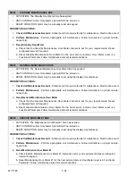
CHECK CONDENSER FAN CIRCUIT
• ACTIVATION: Normal draw for the CDCON contactor coil is 0.05 to 2.0 Amps (12 VDC). The circuit tests
outside this range.
• UNIT CONTROL: Pretrip will fail and display “PRETRIP FAIL AND COMPLETED”.
• RESET CONDITION: Auto Reset if Pretrip is started again, or alarm may be manually reset via keypad or
by turning the unit off, then back on again.
NOTE: Follow the steps below until a problem is found. Once a repair or correction has been made, clear the
alarm(s). (See Note 1 in
Section.) Operate the unit through the appropriate modes to see if any active
alarm occurs. Continue with the steps below as necessary.
CORRECTIVE ACTIONS:
1.
Check CDCON
a. Inspect CDCON contactor coil and wire connections. Verify there is no damage to coil, and no
damage, moisture, or corrosion in connections.
b. Check contactor coil resistance. Refer to
.
2.
Check CDCON Amp Draw
- Check CDCON contactor coil amp draw. Use Component Test Mode (
) to test. Refer to
for amp values. View current draw in Component Test Mode
screen.
3.
Check CDCON Wiring
- Inspect harness & control box connector pins & terminals. (See wiring sche-
matic
.) Verify there is no physical damage to harness, and no damage, moisture, or corro-
sion in connectors.
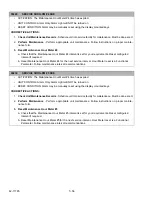
P00207
CHECK COMPRESSOR CONTACT CIRC
• ACTIVATION: Normal draw for the CCON contactor coil is 0.0 to 1.0 Amps (12 VDC). The circuit tests
outside this range.
• UNIT CONTROL: Pretrip will fail and display “PRETRIP FAIL AND COMPLETED”.
• RESET CONDITION: Auto Reset if Pretrip is started again, or alarm may be manually reset via keypad or
by turning the unit off, then back on again.
NOTE: Follow the steps below until a problem is found. Once a repair or correction has been made, clear the
alarm(s). (See Note 1 in
Section.) Operate the unit through the appropriate modes to see if any active
alarm occurs. Continue with the steps below as necessary.
CORRECTIVE ACTIONS:
1.
Check CCON
a. Inspect CCON contactor coils and wire connections. Verify there is no damage to coil, and no
damage, moisture, or corrosion in connections.
b. Check contactor coil resistance. Refer to
.
2.
Check CCON Amp Draw
a. Check CCON contactor coil amp draw. Use Component Test Mode (
) to test. Refer
to
for correct electrical values. View current draw in Component Test Mode screen.
b. Listen for CCON to pull in. If CCON contactor pulls in, CCON is OK. If CCON contactor does not
pull in, check for 12 VDC at CCON coil. 12 VDC indicates defective CCON coil.
3.
Check CCON Wiring
- Inspect harness & control box connector pins & terminals. (See wiring schematic
.) Verify there is no physical damage to harness, and no damage, moisture, or corrosion in
connectors.
Содержание VECTOR 8100
Страница 2: ......
Страница 4: ......
Страница 12: ...62 11785 viii ...
Страница 16: ...62 11640 12 ...
Страница 18: ...62 11785 ...
Страница 24: ...62 11785 1 6 1 3 SAFETY DECALS ...
Страница 25: ...1 7 62 11785 ...
Страница 26: ...62 11785 1 8 ...
Страница 27: ...1 9 62 11785 ...
Страница 28: ...62 11785 1 10 ...
Страница 30: ...62 11785 ...
Страница 50: ...62 11785 ...
Страница 82: ...62 11785 ...
Страница 96: ...62 11785 4 14 ...
Страница 98: ...62 11785 ...
Страница 129: ...5 31 62 11785 ...
Страница 130: ...62 11785 5 32 ...
Страница 134: ...62 11785 6 4 ...
Страница 138: ...62 11785 ...
Страница 230: ...62 11785 ...
Страница 271: ...8 41 62 11785 ...
Страница 272: ...62 11785 8 42 ...
Страница 274: ...62 11785 ...
Страница 286: ......
Страница 287: ......
Страница 288: ...62 11785 10 8 ...
Страница 292: ......
Страница 293: ......