


2–15
62-11785
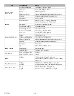
2.10 COMPONENT RESISTANCE & CURRENT DRAW DATA
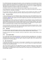
2.11 SAFETY DEVICES
The system is protected from high pressure conditions which may occur when exposed to very high temperatures
(such as a fire) by a fusible plug mounted in the receiver. Under very high temperature conditions (refer to
) the plug will melt, releasing the refrigerant pressure.
System components are protected from damage caused by unsafe operating conditions by automatic shut-down of
the unit when such conditions occur. This is accomplished by the safety devices listed in the following table and the
fuses shown in
and
.
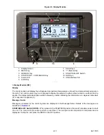
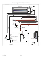
2.12 REFRIGERATION CIRCUIT DURING COOLING
When cooling, the unit operates as a vapor compression refrigeration system. The main components of the system
are:
• scroll compressor
• air-cooled condenser
• evaporator expansion valve
• direct expansion evaporator
• economizer circuit.
The refrigeration system will operate in one of three modes; Standard, Economized or Null. In addition, the system
may also operate in Liquid Injection mode. At start and during periods of high refrigeration system load, the system
will operate in standard mode. This allows the system to place the unit in operation at reduced capacity and
measure actual load. If the microprocessor calculates additional capacity is required and power is available
(periods of high load or during pull-down), the system will transition to economized mode.
2.12.1
Standard Mode
), the compressor raises the pressure and the temperature of the refrigerant and
forces it into the condenser channels. The condenser fans circulate surrounding air over the outside of the
condenser. The channels have fins designed to improve the transfer of heat from the refrigerant gas to the air. This
removal of heat causes the refrigerant to condense. Liquid refrigerant leaves the condenser and flows to the
receiver.
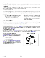
The receiver stores the additional charge necessary for low ambient operation. The receiver is equipped with a
fusible plug. The refrigerant leaves the receiver and flows through the liquid line service valve to the subcooler. The
subcooler occupies a portion of the main condensing coil surface and gives off further heat to the passing air.
The refrigerant then flows through a filter-drier where an absorbent keeps the refrigerant clean and dry.
The liquid then flows through the economizer (which is not active in standard mode) and into the evaporator
expansion valve (EVXV). The EVXV reduces the pressure of the liquid and meters the flow of liquid refrigerant to
the evaporator to obtain maximum use of the evaporator heat transfer surface.
Component
Ohms
Amps
Contactor Coil (HTCON1, HTCON2, CDCON,
1EVCON)
48 Ohms ±10%
0.25 Amps ±10%
Contactor Coil (PSCON, PSCON2, CCON)
0.6 Ohms ±10% Contacts Open
48 Ohms Contacts Held Closed
0.25 Amps ±10%
Liquid Injection Solenoid Valve (LIV)
7.2 Ohms ±3%
1.65 Amps ±3%
Unsafe Conditions
Safety Device
Device Setting
Excessive operating pressure
High Pressure Switch (HPS)
Содержание VECTOR 8100
Страница 2: ......
Страница 4: ......
Страница 12: ...62 11785 viii ...
Страница 16: ...62 11640 12 ...
Страница 18: ...62 11785 ...
Страница 24: ...62 11785 1 6 1 3 SAFETY DECALS ...
Страница 25: ...1 7 62 11785 ...
Страница 26: ...62 11785 1 8 ...
Страница 27: ...1 9 62 11785 ...
Страница 28: ...62 11785 1 10 ...
Страница 30: ...62 11785 ...
Страница 50: ...62 11785 ...
Страница 82: ...62 11785 ...
Страница 96: ...62 11785 4 14 ...
Страница 98: ...62 11785 ...
Страница 129: ...5 31 62 11785 ...
Страница 130: ...62 11785 5 32 ...
Страница 134: ...62 11785 6 4 ...
Страница 138: ...62 11785 ...
Страница 230: ...62 11785 ...
Страница 271: ...8 41 62 11785 ...
Страница 272: ...62 11785 8 42 ...
Страница 274: ...62 11785 ...
Страница 286: ......
Страница 287: ......
Страница 288: ...62 11785 10 8 ...
Страница 292: ......
Страница 293: ......