


7–45
62-11785
P00187
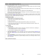
CHECK HEATER 1 CIRCUIT
This device is checked twice in Pretrip - once in Test 2 and again in Test 7.
• ACTIVATION TEST 2: (unit not running): Normal draw for the 1HTCON1 coil is 0.05 to 1.0 Amps (12
VDC). The circuit tests outside this range.
• ACTIVATION TEST 7: (unit running): Normal draw for the 1HTCON1 heaters is 1.0 to 3.5 Amps (460
VAC). The circuit tests outside this range.
• UNIT CONTROL: Pretrip will fail and display “PRETRIP FAIL AND COMPLETED”.
• RESET CONDITION: Auto Reset if Pretrip is started again or alarm may be manually reset via keypad or
by turning the unit off then back on again.
NOTE: Follow the steps below until a problem is found. Once a repair or correction has been made, clear the
alarm(s). (Refer to Note 1 in
Section.) Operate the unit through the appropriate modes to see if any active
alarm occurs. Continue with the steps below as necessary.
CORRECTIVE ACTIONS:
1.
Determine Which Test This Alarm Occurred In
a. Review active alarm list. Make a note of all alarms.
b. Clear active alarm list.
c. Restart and monitor Pretrip. Stop Pretrip during Test #3 by holding = Key for 6 seconds.
d. Review active alarm list. If alarm is present for alarm P00187, follow steps 2 through 5. If alarm is
not present, follow steps 6 through 9.
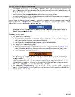
12 VDC CIRCUIT
2.
Check 1HTCON1
a. Inspect heater contactor coil and wire connections. Verify no damage to coil. Wire connections to
contactor coil are tight. No damaged or corroded wires to contactor coil.
b. Check contactor coil resistance. Refer to
for correct electrical values.
3.
Check 1HTCON1 Amp Draw
- Check 1HTCON1 amp draw. Use Component Test Mode (
to test. Refer to
for correct electrical values. View current draw in Component Test Mode
screen.
4.
Check 1HTCON1 Wiring
- Inspect harness & control box connector pins & terminals. (See wiring sche-
matic
.) Verify there is no physical damage to harness, and no damage, moisture, or corro-
sion in connectors.
5.
Check Evaporator High Temperature Switch (EVHTS)
- Inspect for open EVHTS per wiring schematic
. If open, replace switch as required.
Alarm continued on next page...
Содержание VECTOR 8100
Страница 2: ......
Страница 4: ......
Страница 12: ...62 11785 viii ...
Страница 16: ...62 11640 12 ...
Страница 18: ...62 11785 ...
Страница 24: ...62 11785 1 6 1 3 SAFETY DECALS ...
Страница 25: ...1 7 62 11785 ...
Страница 26: ...62 11785 1 8 ...
Страница 27: ...1 9 62 11785 ...
Страница 28: ...62 11785 1 10 ...
Страница 30: ...62 11785 ...
Страница 50: ...62 11785 ...
Страница 82: ...62 11785 ...
Страница 96: ...62 11785 4 14 ...
Страница 98: ...62 11785 ...
Страница 129: ...5 31 62 11785 ...
Страница 130: ...62 11785 5 32 ...
Страница 134: ...62 11785 6 4 ...
Страница 138: ...62 11785 ...
Страница 230: ...62 11785 ...
Страница 271: ...8 41 62 11785 ...
Страница 272: ...62 11785 8 42 ...
Страница 274: ...62 11785 ...
Страница 286: ......
Страница 287: ......
Страница 288: ...62 11785 10 8 ...
Страница 292: ......
Страница 293: ......