


4–21
T-372
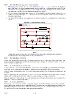
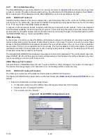
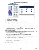
2. Calibrate the three USDA probes by ice bathing the probes and performing the calibration function with the
DataLINE. This calibration procedure generates the probe offsets which are stored in the controller and
applied to the USDA sensors for use in generating sensor type reports
(see
).
Figure 4.12 DataCorder Probe Calibration Screen
3. Pre-cool the container to the treatment temperature or below.
4. Install the controller battery pack (if not already installed).
5. Check the battery status by pressing the CODE SELECT key and using the Arrow keys to bring up code
Cd19. Select btESt.
6. Place the three probes. Refer to the USDA Treatment Manual for directions on placement of probes in fruit
and probe locations in container.
Sensor 1 (USDA1): Place in a box at the top of the stack of the fruit nearest to the air return intake.
Sensor 2 (USDA2): Place slightly aft of the middle of the container, halfway between the top and bottom
of the stack.
Sensor 3 (USDA3): Place one pallet stack in from the doors of the container, halfway between the top
and bottom of the stack.
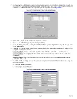
7. To initiate USDA recording, connect the personal computer and enter ISO header information using the
DataLINE software.
a. Enter ISO header information.
b. Enter a trip comment if desired.
Figure 4.13 DataCorder Probe Calibration Screen
Содержание PrimeLINE 69NT40-571-001
Страница 2: ......
Страница 4: ......
Страница 14: ......
Страница 36: ......
Страница 110: ......
Страница 116: ......
Страница 171: ...8 1 T 372 SECTION 8 ELECTRICAL WIRING SCHEMATIC AND DIAGRAMS Figure 8 1 Legend Standard Unit Configuration ...
Страница 172: ...T 372 8 2 ELECTRICAL WIRING SCHEMATIC AND DIAGRAMS Figure 8 2 Schematic Diagram Based on Drawing 62 11957 ...
Страница 176: ......
Страница 178: ......
Страница 180: ......
Страница 184: ......
Страница 185: ......