


T-372
7–28
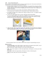
NOTE
There is a small spacer tube between the top of the valve and the 12 VDC coil that needs to be reinstalled into
the solenoid valve coil. When removing the coil, it may fall out when lifted from the valve body. Take care that the
spacer is not lost; the valve will not function correctly without it.
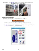
4. Remove the clamps holding the DUV to the discharge line.
5. Loosen the nuts attaching the DUV to the top of the compressor.
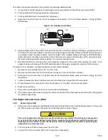
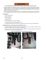
6. Remove the valve. The preferred method of removing the solenoid valve is to cut the connection between
the brazed section and the valve, using a small tube cutter. Remove valve. (see
).
Alternatively, use a wet rag to keep valve cool. Heat outlet connection to valve body and remove valve.
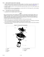
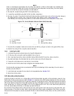
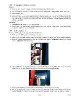
Figure 7.19 View of Digital Unloader Valve (DUV) Assembly
1) O-ring (hidden)
2) Sleeve
3) Hex Nut, 1/2 OD
4) Screen Valve Strainer
5) Tube
6) Solenoid Valve Body
- - - - -
7. Examine the compressor and service valves. Ensure that the o-ring is not stuck in the gland of the valve.
8. Discard the o-ring on the o-ring face seal connection.
7.24.2
Installing the DUV
1. Lubricate the gland shoulder area and o-ring with refrigerant oil.
2. Fit the new valve in position and hand-tighten the o-ring nut.
3. Use a wet rag to keep the valve cool while brazing. Braze the DUV to service valve connection.
4. Reinstall and tighten the brackets that secure the valve body to the discharge line.
5. Torque the o-ring face seal connections to 18 to 20 ft-lbs.
6. Install the coil onto the valve body and tighten the attachment bolt.
NOTE
Confirm that the small spacer tube is inserted into the coil prior to attaching it to the valve body. The valve will not
function correctly without it.
7. Leak check and evacuate the low side of unit as applicable. See
.
8. Open the service valves.
7.25 Valve Override Controls
Controller function code Cd41 is a configurable code that allows timed operation of the automatic valves for trou
-
bleshooting. Test sequences are provided in
. Capacity mode (CAP) allows alignment of the economizer
solenoid valve in the standard and economized operating configurations. DUV Capacity Modulation% Setting
(PCnt) and Electronic Expansion Valve (EEV) allows opening of the digital unloader valve and electronic expansion
valve, respectively, to various percentages. If the unit is equipped with an LIV, the Liquid Valve Setting allows the
LIV to be automatically controlled, or manually opened and closed.
The Override Timer (tIM) selection is also provided to enter a time period of up to five minutes, during which the over
-
ride(s) are active. If the timer is active, valve override selections will take place immediately. If the timer is not active,
changes will not take place for a few seconds after the timer is started. When the timer times out, the override function
2
1
4
5
6
3
Содержание PrimeLINE 69NT40-571-001
Страница 2: ......
Страница 4: ......
Страница 14: ......
Страница 36: ......
Страница 110: ......
Страница 116: ......
Страница 171: ...8 1 T 372 SECTION 8 ELECTRICAL WIRING SCHEMATIC AND DIAGRAMS Figure 8 1 Legend Standard Unit Configuration ...
Страница 172: ...T 372 8 2 ELECTRICAL WIRING SCHEMATIC AND DIAGRAMS Figure 8 2 Schematic Diagram Based on Drawing 62 11957 ...
Страница 176: ......
Страница 178: ......
Страница 180: ......
Страница 184: ......
Страница 185: ......