


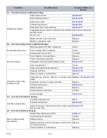


T-372
7–2
When both valves are backseated (all the way out), high pressure vapor will flow into the low side.
When the suction pressure valve (1) is open and the discharge pressure valve (4) shut, the system can be charged
through the utility connection (6). Oil can also be added to the system.
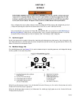
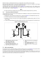
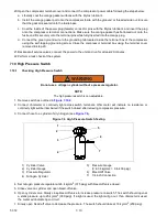
A manifold gauge / hose set with self-sealing hoses (see
) is required for service of the models covered
within this manual. The manifold gauge/hose set is available from Carrier Transicold (part number 07-00294-00,
which includes items 1 through 6,
).
NOTE
It is recommended that the manifold gauge set be dedicated to specified refrigerant (R-134a or R-513A).
7.2.1
Evacuating the Manifold Gauge Set
If the manifold gauge / hose set is new or was exposed to the atmosphere, it will need to be evacuated to remove
contaminants and air as follows:
1. Backseat (turn counterclockwise) both field service couplings (see
) and midseat both hand valves.
2. Connect the yellow hose to a vacuum pump and refrigerant cylinder.
3. Evacuate to 10 inches of vacuum and then charge with refrigerant to a slightly positive pressure of 0.1 kg /
cm2 (1.0 psig).
4. Frontseat both manifold gauge set valves and disconnect from cylinder. The gauge set is now ready for use.
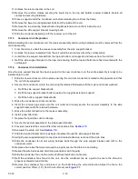
Figure 7.2 Manifold Gauge/Hose Set
1) RED Refrigeration and/or Evacuation
Hose (SAE J2196/R-134a)
2) Hose Fitting (0.5-16 Acme)
3) YELLOW Refrigeration and/or
Evacuation Hose (SAE J2196/R-134a)
4) Hose Fitting with O-ring (M14 x 1.5)
5) High Side Field Service Coupling (Red
Knob)
6) BLUE Refrigeration and/or Evacuation
Hose (SAE J2196/R-134a)
7) Low Side Field Service Coupling (Blue
Knob)
- - - - -
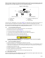
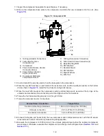
7.3 Service Connections
The compressor suction, compressor discharge, and the liquid line service valves (see
) are provided with a
double seat and an access valve which enables servicing of the compressor and refrigerant lines.
Turning the valve stem clockwise (all the way forward) will frontseat the valve to close off the line connection and
open a path to the access valve. Turning the stem counterclockwise (all the way out) will backseat the valve to
open the line connection and close off the path to the access valve.
To Low Side
Access Valve
To High Side
Access Valve
1
2
3
2
6
4
7
4
5
Содержание PrimeLINE 69NT40-571-001
Страница 2: ......
Страница 4: ......
Страница 14: ......
Страница 36: ......
Страница 110: ......
Страница 116: ......
Страница 171: ...8 1 T 372 SECTION 8 ELECTRICAL WIRING SCHEMATIC AND DIAGRAMS Figure 8 1 Legend Standard Unit Configuration ...
Страница 172: ...T 372 8 2 ELECTRICAL WIRING SCHEMATIC AND DIAGRAMS Figure 8 2 Schematic Diagram Based on Drawing 62 11957 ...
Страница 176: ......
Страница 178: ......
Страница 180: ......
Страница 184: ......
Страница 185: ......