background image

Technical Data 

SPE series 


18 

Operating manual 

12.16 


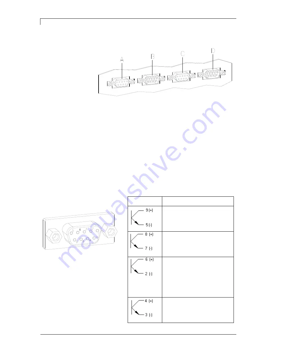
3.1  Control inputs and outputs (version I) 


Figure 3 

 
A = External output 1-4 (Output I) 
B = External input 1-4 (Input I) 
C = External output 5-8 (Output II) 
D = External input 5-8 (Input II) 
 
By means of the signal outputs different operating states of the print 
module can be queried. 

The signal outputs are provided by two 9-pin SUB-D-bushings 
(OUTPUT I and OUTPUT II) on the back side of the control unit. 

They consist of optocoupler semiconductor sections, which are 
connected through and/or blocked according to different operating 
states. 

The maximum allowable current in a semiconductor section is 
lmax = 30 mA. 


Output I 
Figure 3, A 


Figure 4 

PIN (bushing) 

Output I 


Out 1: Error message 

Each error status such as ribbon 
error is displayed. 


Out 2: Print order 

The print module was activated by 
a print order. 


Out 3: Generation 

The current label data is processed. 
In case in dispensing mode either 
dispensing photocell or dispensing 
photocell continuous is selected it is 
indicated if a label is under 
photocell and ready to pick up. 


Out 4: Layout print 

The content of print memory is 
transferred on the printable medium 
by means of the printhead. 


Plug connection - back 
side of control unit 

Control outputs 

Содержание SPE series

Страница 1: ......

Страница 2: ...s between manual and device can occur Please check www carl valentin de for the latest update Trademarks All named brands or trademarks are registered brands or registered trademarks of their respective owners and may not be separately labelled It must not be concluded from the missing labelling that it is not a registered brand or a registered trademark Carl Valentin print modules comply with the...

Страница 3: ...ssing mode 32 5 3 Loading transfer ribbon 33 6 Keyboard 35 6 1 Keyboard assignment standard 35 6 2 Keyboard assignment text entry customized memory card 36 7 Function menu 39 7 1 Print settings 43 7 2 Label layout 44 7 3 Device settings 46 7 4 Dispenser I O 49 7 5 Remote console 52 7 6 Interface 52 7 7 Emulation 54 7 8 Date time 55 7 9 Service functions 56 7 10 Main menu 59 8 Options 61 8 1 Ribbon...

Страница 4: ...rating manual 12 16 11 Error correction 83 12 Additional information 95 12 1 Column printing 95 12 2 Password 96 12 3 Hotstart 98 12 4 Backfeed delay 100 12 5 Transmission photocells 102 12 6 Ultrasonic photocell option 103 13 Index 105 ...

Страница 5: ...quipped with a parallel and serial interface The print module automatically recognizes by which interface it is controlled Time saving update is possible by interface Thanks to the large number of options the print module can be adapted to each task 1 1 Intended use The print module is a state of the art device which complies with the recognized safety related rules and regulations Despite this a ...

Страница 6: ...ed and disposed of by the manufacturer Valentin products accordingly labelled can therefore be returned to Carl Valentin GmbH This way you can be sure your old equipment will be disposed of correctly Carl Valentin GmbH thereby fulfils all obligations regarding timely disposal of old equipment and facilitates the smooth reselling of these products Please understand that we can only take back equipm...

Страница 7: ...II 4 Version I Version II SUB D plug 9 pin External input 5 8 see chapter 3 1 SUB D plug 15 pin External bushing I O 24 see chapter 3 2 5 Centronics interface 6 RS 232 interface 7 Ethernet interface option 8 Connecting cable power 9 Connecting cable motor 10 Connecting cable signal 11 Connecting cable sensors 12 Power supply 13 PS 2 keyboard connection 14 USB interface Control unit ...

Страница 8: ...Important notes SPE series 8 Operating manual 12 16 Figure 2 1 Connection for winder 2 Motors 3 Printhead signal 4 Sensors 5 Printhead power Rear panel of mechanics ...

Страница 9: ...pen printing unit due to construction the requirements of EN60950 1 regarding fire protection casing are not fulfilled These must be ensured by the installation into the end device The print unit can get hot during printing Do not touch the printhead during operation Cool down the print unit before changing material removal or adjustment Carry out only the actions described in these operating inst...

Страница 10: ...connect the device from the mains supply and wait approx 2 3 minutes until the power supply unit has discharged 2 1 Warnings Warnings are presented with three signal words for the different levels of danger DANGER identifies an extraordinarily great and immediate danger which could lead to serious injury or even death WARNING identifies a possible danger would could lead to serious bodily injury o...

Страница 11: ...regularly Content of the training are chapter 2 2 Operating conditions chapter 5 Loading media and chapter 10 Maintenance and cleaning These indications are also valid for someone else s equipment supplied by us Only use original spare and exchange parts Please contact the manufacturer with respect to spare wear parts The installation place of print module should be even free of vibration and curr...

Страница 12: ...g to EN 55022 09 2003 Interference field power according to EN 55022 09 2003 Immunity to interference according to EN 61000 6 2 03 2006 Stray radiation against discharge of static electricity according to EN 61000 4 2 12 2001 Electromagnetic fields according to EN 61000 4 3 11 2003 Fast transient burst according to EN 61000 4 4 07 2005 Surge according to EN 61000 4 5 12 2001 High frequency tension...

Страница 13: ...es and connectors are necessary in order to avoid radiant emittance and receipt of electrical disturbances Allowable lines Shielded line 4 x 2 x 0 14 mm 4 x 2 x AWG 26 6 x 2 x 0 14 mm 6 x 2 x AWG 26 12 x 2 x 0 14 mm 12 x 2 x AWG 26 Sending and receiving lines have to be twisted in pairs Maximum line length with interface V 24 RS 232C 3 m with shielding with Centronics 3 m with shielding with USB 3...

Страница 14: ...nt modules Control the correct handling of our products and repeat training We do not guarantee that all features described in this manual exist in all models Caused by our efforts to continue further development and improvement technical data might change without notice By further developments or regulations of the country illustrations and examples shown in the manual can be different from the d...

Страница 15: ...mm 1200 mm 1100 mm 800 mm 700 mm 800 mm 700 mm Label Sensor transmission Transfer Ribbon Ink outside inside Max Roll Diameter Ø 90 mm Core Diameter 25 4 mm 1 Max Length 450 m Max Width 110 mm 110 mm 110 mm 110 mm 170 mm 170 mm Dimensions in mm width x height x depth Print Mechanics H 300 D 245 300 x H x D 300 x H x D 300 x H x D 300 x H x D 360 x H x D 360 x H x D Control Unit 285x140x360 Weight i...

Страница 16: ...Size in width and height 0 8 5 6 Zoom 2 9 Orientation 0 90 180 270 Vector fonts TrueType fonts Size in width and height 1 99 mm Variable zoom Orientation 0 90 180 270 Font attributes Depending on character font bold italic inverse vertical Font width Variable Bar Codes 1D bar codes CODABAR Code 128 Code 2 5 interleaved Code 39 Code 39 extended Code 93 EAN 13 EAN 8 EAN ADD ON GS1 128 Identcode ITF ...

Страница 17: ...tion Inputs outputs Windows printer driver Transfer ribbon savings only 107 12 and 160 12 Ultrasonic photocell only 107 12 and 160 12 Label dispensing unit Label unwinding unit Rewinder for supporting paper Compact Flash Card slot PCMCIA cards Compact Flash cards RS422 interface RS485 interface Ethernet interface Label design software Labelstar Office Standard equipment Optional equipment ...

Страница 18: ...rough and or blocked according to different operating states The maximum allowable current in a semiconductor section is lmax 30 mA Output I Figure 3 A Figure 4 PIN bushing Output I Out 1 Error message Each error status such as ribbon error is displayed Out 2 Print order The print module was activated by a print order Out 3 Generation The current label data is processed In case in dispensing mode ...

Страница 19: ...ut II Figure 3 C Figure 6 PIN bushing Output II Out 5 Print Ready signal It is indicated if the print module is ready to process a start impulse In contrary to the print order signal the generating time is taken into consideration Out 6 Not used Out 7 Not used Out 8 Prior warning of transfer ribbon end Example ...

Страница 20: ...uts at Input I are electroplated separated and have to be provided with an external tension source The signal level is active HIGH Input I Figure 3 B Figure 7 PIN pin Input I In 1 Print start In 2 Not used In 3 Reset external counter In 4 Not used Connection of a switch with 24V voltage supply by In 1 Figure 8 Control inputs Example ...

Страница 21: ...SPE series Technical Data 12 16 Operating manual 21 Input II Figure 3 D Figure 9 PIN pin Input II In 5 Not used In 6 Not used In 7 Not used In 8 Not used ...

Страница 22: ...hrough and or blocked according to different operating states The maximum allowable current in a semiconductor section is lmax 30 mA Output I Figure 10 A Figure 11 PIN bushing Output I Out 1 Error message Each error status such as ribbon error is displayed Out 2 Print order The print module was activated by a print order Out 3 Generation The current label data is processed In case in dispensing mo...

Страница 23: ...ut II Figure 10 C Figure 13 PIN bushing Output II Out 5 Print Ready signal It is indicated if the print module is ready to process a start impulse In contrary to the print order signal the generating time is taken into consideration Out 6 Not used Out 7 Not used Out 8 Prior warning of transfer ribbon end Example ...

Страница 24: ...puts at Input I are galvanic separated and have to be provided with an external tension source The signal level is active HIGH Input I Figure 10 B Figure 14 PIN pin Input I In 1 Print start In 2 Not used In 3 Reset external counter In 4 Not used Connection of a switch with 24V voltage supply by In 1 Figure 15 Control inputs Example ...

Страница 25: ... 15 pole and provides user sided 24V 100mA In case of using this bushing exists no galvanic separation Figure 16 PIN Function 1 6 Gnd 5 10 24 V 100 mA 3 Print start NPN initiator 2 Print start PNP initiator 4 Print start by potential free contact 14 7 Signal lamp 24 V 100 mA error 13 Example 1 Example 2 Example 3 ...

Страница 26: ...Technical Data SPE series 26 Operating manual 12 16 3 3 Signal diagrams Figure 17 Figure 18 Dispensing mode I O dynamic Dispensing mode I O dynamic continuous ...

Страница 27: ...bon roll Empty core mounted on transfer ribbon rewinder Cleaning foil for printhead Documentation CD with printer drivers NOTICE Retain original packaging for subsequent transport 4 1 Setting up the print module CAUTION The print module and the print media can be damaged by moisture and water Set up the print module only in a dry place protected from sprayed water Mount the print mechanics on a vi...

Страница 28: ...power connection socket 2 Insert plug of power cable into a grounded electrical outlet NOTICE Insufficient or missing grounding can cause faults during operation Ensure that all computers and connection cables connected to the print module are grounded Connect print module to computer or network with a suitable cable 4 3 Switching the print module on and off Once all connections have been made Swi...

Страница 29: ...asuring in menu Label layout Measure label see chapter 7 2 Label layout on page 44 Press key to finish measuring NOTICE To enable correct measuring at least two completed labels have to be passed through not for continuous labels During measuring the label and gap length small differences can occur Therefore the values can be set manually in Label layout Label and Gap menu ...

Страница 30: ......

Страница 31: ... bottom until it locks 6 In order to move the printhead A down turn the red pressure lever B in clockwise direction until it locks 7 Adjust the adjusting rings F of the label guiding to the width of material 8 Lift the dispensing whip G by pulling the knurled knob I outwards to the bottom 9 Strip some labels from the backing paper and lead the backing material over the dispensing whip I and betwee...

Страница 32: ...C by pulling the red bolt to the top 4 Lead the label material below the label guiding D and take care that the label runs through the photocell E 5 Press the engine support C again downwards until it locks 6 In order to move the printhead A down turn the red pressure lever B in clockwise direction until it locks 7 Adjust the adjusting rings F of the label guiding to the width of material 8 Close ...

Страница 33: ...roller cleaner 97 20 002 For detailed information please see page 74 The handling instructions for the use of Isopropanol IPA must be observed In the case of skin or eye contact immediately wash off the fluid thoroughly with running water If the irritation persists consult a doctor Ensure good ventilation 1 Open the print module cover 2 Open printhead A by turning the red pressure lever B anticloc...

Страница 34: ...r B in clockwise direction until it locks 7 Close the print module cover NOTICE As for the electrostatic unloading the thin coating of the thermal printhead or other electronic parts can be damaged the transfer ribbon should be antistatic The use of wrong materials can lead to malfunctions and the guarantee can expire ...

Страница 35: ...print order with key No further label of the print order is printed Memory Change to Compact Flash card menu Quant Change to number of copies menu Press keys and to select the number of copies that are to print Forwards In main menu printing carriages moves to the before set service position Change to next input field Press keys and to change values Backwards In main menu printing carriage moves b...

Страница 36: ... Symbol Mode 0 Standard starting with figures M Starting with capital letters m Starting with small letters A Input Alt a Input Alt is switched off after one character Mode 0 This mode is displayed as default At first the figure which corresponds to the key is displayed then all capital and afterwards the small letters Mode M At first all capital then the small letters and at last the correspondin...

Страница 37: ...d of entry Memory Entry mode selection Quant Delete character at cursor position If the cursor is behind the last character the last one is deleted Character is only deleted if it was before entered by the character block Forwards Cursor one position to the right Backwards Cursor one position to the left 0 9 Character block Entry of desired data F1 F2 Function keys No function C Function key Delet...

Страница 38: ......

Страница 39: ...ting Measure label Label type Material selection Photocell Scan position Label error length Synchronisation Flip label Rotate label Alignment Automatic label measurement Label Layout Field handling Codepage External parameters Buzzer Display Language Keyboard Customized entry Hotstart Autoload Manual reprint Backfeed Delay Password Device Settings Label confirmation Standard label ...

Страница 40: ...Debounce Start signal delay Dispenser I O option I O Protocol Save signal On Off Ribbon Save option IP address Netmask Standard Gateway Speed Duplex DHCP Printer name Network option Operating modes Bad readings Label feed Scanner type Setup Offset Scan length Interface COM2 Scanner option Port Interval Remote Console ...

Страница 41: ...ata memory Parallel port Port test COM2 Baud Parity Data bits Stop bit Protocol Printhead resolution Drive mapping Emulation Set date time Summertime Start of summertime format Start of summertime date Start of summertime time End of summertime format End of summertime date End of summertime time Time shifting Date Time ...

Страница 42: ... resistance Printhead temperature Motor ramp Print examples Input Output Online Offline Transfer ribbon prior warning Zero point adjustment Service Functions Cutter photocell Load layout Change directory Load file Save layout Save configuration Delete file Formatting CF Card USB Stick Copying Firmware update ...

Страница 43: ...essage appears at the display of control unit strong sensibility The print module reacts immediately to the end of the transfer ribbon weak sensibility The print module reacts at approx 1 3 more slowly to the end of the transfer ribbon Press key to arrive at the next menu item Y displacement Indication of initial point displacement in mm The label is moved vertically Value range 30 0 90 0 Press ke...

Страница 44: ...tops automatically after termination of measuring The determined values are displayed and saved Press key to arrive at the next menu item Label type Generally adhesive labels are set Press key to select continuous labels If the menu label length gap length contains a gap value this value is added to the label length Press key to arrive at the next menu item Material Selection of the used label and...

Страница 45: ...herwise this can cause problems in positioning Press key to arrive at the next menu item Rotate label According to standard the label is printed ahead with a rotation of 0 If the function is activated the label is rotated by 180 and printed in reading direction Press key to arrive at the next menu item Alignment The adjustment of label is effected only after flip rotate label i e the adjustment is...

Страница 46: ... possibilities are available ANSI character set Codepage 437 Codepage 850 GEM German GEM English GEM French GEM Swedish GEM Danish Press key to arrive at the next menu item External parameters Label dimension only The parameters for label length gap length and label width can be transferred to the printer All other parameter settings are to be made directly at the printer On Sending parameters suc...

Страница 47: ... 3 Hotstart on page 98 Press key to arrive at the next menu item Autoload On A label which was loaded once from the memory card can be loaded again automatically after a restart of printer Procedure The used label is saved onto memory card The label is loaded from memory card and printed After switching the printer Off and again On the label is loaded from memory card automatically and can be prin...

Страница 48: ... By a password several functions can be blocked so the user cannot work with them There are several applications in which the use of password protection makes sense see chapter 12 2 Password on page 96 Press key to arrive at the next menu item Label confirmation On A new print order is only printed after confirmation at the device An already active continuing print order is printed as long as the ...

Страница 49: ...ntinuous means that it is printed as long as new data is transferred via interface The set dispenser offset is not taken into consideration I O dynamic The external signal is evaluated dynamically i e is the print module in waiting mode a single label is printed at each signal changing After the print the set dispenser offset is executed i e a backfeed is effected I O dynamic continuous You can fi...

Страница 50: ...nly taken into consideration for the operating modes I O static I O dynamic I O static continuous and I O dynamic continuous Press key to arrive at the next parameter OUT signal level Indication of signal level for output signal active signal level is high 1 active signal level is low 0 s status can be affected by interface Press key to arrive at the next parameter Debounce Indication of debounce ...

Страница 51: ... registered from the print module The print module starts printing the next label immediately after finishing the current one Therefore time can be saved and performance be increased Off The start signal for the next label can only be released if the current label is printed to the end and the print module is again in waiting state output ready set If the start signal was released already before s...

Страница 52: ... 38400 and 57600 P Parity N No parity E Even O Odd Please observe that the settings correspond to those of the print module D Data bits Setting of data bits Value range 7 or 8 Bits S Stop bits Indication of stop bits between bytes Value range 1 or 2 stop bits Press key to arrive at the next menu item COM2 0 serial interface Off 1 serial interface On 2 serial Interface On no error message occurs in...

Страница 53: ...er the printer buffer receives data as long as it is filled Advanced During a current print order data is received and processed Off After starting a print order no more data is received Press key to arrive at the next menu item Parallel port SPP Standard Parallel Port ECP Extended Capabilities Port grants a fast data transmission but it is only to set at PCs of newer version Please observe that t...

Страница 54: ...d resolution of the emulated printer must be set e g 11 8 Dot mm 300 dpi NOTICE If the printhead resolution of the Zebra printer differs from that of the Valentin printer then the size of objects e g texts graphics complies not exactly Press key to arrive at the next menu item Drive mapping The access to Zebra drives B Memory Card R RAM Disk standard drive if not indicated is rerouted to the corre...

Страница 55: ... start This entry refers to the previously selected format Example summertime is automatically adjusted at last Sunday in March 03 Press key to arrive at the next menu item Start of summertime time By means of this function you can define the time when you want to start summertime Press key to arrive at the next menu item End of summertime format Select the format in which you want to define end o...

Страница 56: ...menu item Photocell parameters DLS Indication of transmission photocell level in Volt RLS Indication of reflexion photocell level in Volt SLS Indication of peel off photocell level in Volt TR Indication of transfer ribbon photocell status either 0 or 1 H Indication of printhead position 0 printhead down 1 printhead up Press key to arrive at the next menu item Paper counter D Indication of printhea...

Страница 57: ...hotocell 1 Print module is equipped with a cutter 0 Print module is not equipped with a cutter CH 1 The cutter is in the initial position and ready for the cutting procedure 0 The cutter is not in the initial position Before you are going to release a cutting procedure you first have to place the cutter in its initial position Press key to arrive at the next menu item Online Offline This function ...

Страница 58: ...sponding I O output is set Reduced print speed Speed on which the printing speed is to be reduced Error The printing system stops when reaching the transfer ribbon advance warning diameter with the message too less ribbon Reduced print speed Setting of the reduced print speed in mm s This can be set in the limits of the normal print speed Press key to arrive at the next menu item Zero point adjust...

Страница 59: ...Indication of software Build version Press key once more for display the following Indication of firmware creation date Press key once more for display the following Indication of firmware creation time Press key once more for display the following Indication of font version of bitmap fonts Press key once more for display the following Indication of font version of vector fonts Press key once more...

Страница 60: ......

Страница 61: ...much lower when using the ribbon save option Press key to access the function menu Press key as long as you arrive at the Ribbon save menu Press key to select the menu Press key so switch the ribbon savings function On or Off 8 2 Network Press key to access the function menu Press key as long as you arrive at the Network menu This menu item can only be selected if a network card is recognised at s...

Страница 62: ...annot be red from the scanner and shows an error message VEtik Label feeding In many cases it is impossible to position the scanner directly at the printhead and therefore with this setting a feeding can be set Value range 1 5 The illustration below clarifies the meaning of this parameter Press key to arrive at the next menu item Scanner type Selection of the connected scanner type For more inform...

Страница 63: ...the switch on and off position of scanner is calculated by means of position and height of bar code onto the label If the parameter Scan Length is not 0 so this defines the length of scan sector The start of scan sector is then set by the parameter Scan Offset The following drawing shows the meaning of parameter Figure 22 Press key to arrive at the next menu item Interface In order to use a scanne...

Страница 64: ......

Страница 65: ...jector knob to take out the card of device B press the lower one Figure 23 The print module handles your memory card as a DOS compatible file system After formatting the memory card the STANDARD directory is automatically available After switching on the print module or inserting the memory card this directory is the current one The directories are displayed with capital letters and the sign The i...

Страница 66: ...d B inside a selected function Press key and to browse the contents of the current directory Press key and to change to the indicated directory Keys Press key and to select the desired label in STANDARD directory Press key to select the label Select the number of labels which you want to print Press key to start the print order After finishing the print order the display shows again the main menu ...

Страница 67: ...save and confirm the selection with key Confirm the query with and the label will be saved After the saving procedure the display shows again the main menu Keys Press key to select the Save configuration menu item As standard the proposed file name is config cfg This name can be changed by the user In this file the printer parameters are saved which are not saved permanent in the internal Flash Pr...

Страница 68: ...ss key to select the Delete file menu item Select directory and or label you want to delete and confirm the selection with key The selected label is deleted from the memory card After the deleting procedure the display shows again the first menu item Load file Keys Press key to select the Format menu item Press key to confirm the selection and the procedure is started When formatting the memory ca...

Страница 69: ...g from A to A res B to B first of all the query regarding the destination card appears on the display Insert card and confirm the query If the content of the card is loaded into the printer internal memory a prompt appears to insert the destination card NOTICE Depending on the storage capacity of memory card this procedure is to be repeated After the copying procedure the display shows again the L...

Страница 70: ......

Страница 71: ...roller see section 10 3 on page 73 Each time the label roll is changed or when the printout and label transport are adversely affected Cleaning printhead see section 10 4 on page 74 Direct thermal printing Each time the label roll is changed Thermal transfer printing Each time the transfer ribbon is changed or when the printout is adversely affected Cleaning label photocell see section 10 5 on pag...

Страница 72: ...solvents to clean the outer surface of the print module Remove dust and paper fuzz in the printing area with a soft brush or vacuum cleaner Clean outer surfaces with an all purpose cleaner 10 2 Cleaning the Transfer Ribbon Drawing Roller A soiled print roll can lead to reduced print quality and can affect transport of material 1 Open cover of printing system 2 Remove labels and transfer ribbon for...

Страница 73: ...ects to clean the print roller Figure 24 1 Open cover of print module 2 Turn red lever B counter clockwise to lift up the printhead A 3 Remove labels and transfer ribbon form the print module 4 Remove deposits with roller cleaner and a soft cloth 5 Turn the roller C manually step by step to clean the complete roller only possible when print module is switched off as otherwise the step motor is ful...

Страница 74: ...ects such as dust etc CAUTION Printhead can be damaged Do not use sharp or hard objects to clean the printhead Do not touch protective glass layer of the printhead Figure 25 1 Open cover of print module 2 Turn red lever B in Figure 24 counter clockwise to lift up the printhead 3 Remove labels and transfer ribbon from the print module 4 Clean printhead surface with special cleaning pen or a cotton ...

Страница 75: ...Figure 26 1 Open cover of print module 2 Turn red lever B in Figure 24 counter clockwise to lift up the printhead 3 Remove labels and transfer ribbon from the print module 4 Blow out the photocell A with pressure gas spray Observe strictly the instructions on the spray can 5 Clean the label photocell A additionally with a cleaning card B before soaked in pure alcohol Move the cleaning card from on...

Страница 76: ...tion tension 4 Printhead 5 Focal line 6 Guiding 7 Knurled screw CAUTION The printhead can be damaged by static electricity discharges and impacts Set up print module on a grounded conductive surface Ground your body e g by wearing a grounded wristband Do not touch contacts on the plug connections 2 3 Do not touch printing line 5 with hard objects or your hands ...

Страница 77: ...g connections 6 Remove plug connections and then remove printhead 3 1 Attach plug connections 2 Position printhead in printhead mounting bracket in such a way that the pins are secured in the corresponding holes in the head plate 3 Lightly keep printhead mounting bracket on the printer roller with one finger and check for correct positioning of the printhead 4 Screw in screw 4 and tighten it 5 Rel...

Страница 78: ...se printhead moves forwards 3 Adjust the parallelism as long as the printing result comes up to your full expectation 4 Tighten again screws 4 Figure 28 5 Start a print order with approx 10 labels and control the correct passage of transfer ribbon After adjusting parallelism and no even strong pressure exists over the complete print width by means of a plate 6 you can set the balance as follows 1 ...

Страница 79: ... the life cycle of printhead 1 Turn pressure screws 9 Figure 28 to change the pressure of printhead 2 Turning the pressure screws 9 Figure 28 as far as they will go in clockwise direction results in a pressure increase of 10N in contrast to the factory setting 3 Turning the pressure screws 9 Figure 28 exactly one rotation from the right stop position counter clockwise results in the factory settin...

Страница 80: ...ug connections 6 Remove plug connections and then remove printhead 3 1 Attach plug connections 2 Position printhead in printhead mounting bracket in such a way that the pins are secured in the corresponding holes in the head plate 3 Lightly keep printhead mounting bracket on the printer roller with one finger and check for correct positioning of the printhead 4 Screw in screw 1 and tighten it 5 Re...

Страница 81: ...approx rotations 2 Adjust the parallelism with the adjusting screws 5 or 9 Figure 29 Clockwise printhead moves backwards Counter clockwise printhead moves forwards 3 Adjust the parallelism as long as the printing result comes up to your full expectation 4 Tighten again screws 1 or 4 Figure 29 5 Start a print order with approx 10 labels and control the correct passage of transfer ribbon After adjus...

Страница 82: ...he life cycle of printhead 1 Turn pressure screws 10 Figure 29 to change the pressure of printhead 2 Turning the pressure screws 10 Figure 29 as far as they will go in clockwise direction results in a pressure increase of 10N in contrast to the factory setting 3 Turning the pressure screws 10 Figure 29 exactly one rotation from the right stop position counter clockwise results in the factory setti...

Страница 83: ...eck position Selected font is not available Check font Selected font is not available Check font While measuring no label was found Set label length is too large Check label length and if labels are inserted correctly Restart measuring anew No label available Soiled label photocell Labels not inserted correctly Insert new label roll Check if labels are inserted correctly Clean the label photocell ...

Страница 84: ...racters of the text is res are not available in the selected font Change text Change font Unknown transferred data record Check sent data Check connection PC module For check digit control the entered res received check digit is wrong Calculate check digit anew Check code data Selected SC factor is invalid for EAN res UPC Check SC factor Entered digits for EAN res UPC are invalid 12 13 Check numbe...

Страница 85: ... Time Clock function is selected but the battery is empty Defective RTC Change battery Change RTC component Interrupted connection CPU memory card Defective memory card interface Check connection CPU memory card interface Check memory card interface No print memory found Check memory assembly on CPU At start of a print order the printhead is open Close the printhead and start print order anew BCD ...

Страница 86: ...th Indicate a shorter path Memory Card is write protected Deactivate write protection Attempt to indicate a directory as file name Correct your entry Attempt to change a file during an access is active Select another file File does not exist on memory card Check file name File name contains invalid characters Correct entry of name remove special characters Internal file system error Please contact...

Страница 87: ...ard drive found Check connection of memory card drive Contact your distributor No memory card is inserted Insert memory card in the slot Error at start of web server Please contact your distributor The direct print module is equipped with the wrong FPGA Please contact your distributor The label length is too long The number of labels per cycle is too much Check label length res the number of label...

Страница 88: ... A page which is not available is selected Check the defined pages The page is not defined Check the print definition Wrong format for customised entry Check the format string Wrong format for date time Check the format string No memory card found If option hotstart was activated a memory card must be inserted Switch off the printer before inserting the memory card Selection of print of several co...

Страница 89: ...onto the label Scanned data does not correspond to defined ID Wrong label loaded from memory card RFID unit cannot recognise a label Displace RFID unit or use an offset Error while checking programmed data Faulty RFID label Check RFID definitions Error at programming the RFID label Label positioning Faulty label Faulty or incomplete definition of RFID data Check RFID data definitions Definition of...

Страница 90: ...ial interface error Check settings for serial data transmission as well as cable module PC No printhead FPGA data available Please contact your responsible distributor Error when programming printhead FPGA Please contact your responsible distributor Sensor signal up is missing option APL 100 Check input signals compressed air supply Sensor signal down is missing option APL 100 Check input signals ...

Страница 91: ... cover is not closed Close the housing cover and start the print order anew Transferred EAN UCC code is invalid Verify bar code data see corresponding specification Printing carriage does not move Check gear belt possibly broken Applicator error Check applicator Applicator Left end position Check LEFT final position switch for correct function and position Check function of pneumatics for cross tr...

Страница 92: ......

Страница 93: ...largest x coordinate i e it has the largest distance to the printhead Press key to change to the function menu Press key as long as to the Label layout menu Press key to confirm the selection Press key as long as the menu item see illustration appears Press key and to set the label width As column width the width of one label is entered e g 20 0 mm Press key and to enter the number of columns Pres...

Страница 94: ... the entry of mask and the function menu By this means the user indeed can print labels but the print module set up and the masks of the labels can t be changed To receive a most flexible password protection the print module functions will be divided into several function groups In the function menu the print parameters can be changed contrast speed mode The password protection prevents modificati...

Страница 95: ... can be done In the first line the user can define the password 4 digit number Press key to switch to the next Press key and to activate deactivate the password protection yes no Press key to change to the second line Press key and to block release individual function groups Press key and to change from one group to the next one F Function menu 0 open 1 locked MC Memory Card 0 open 1 only reading ...

Страница 96: ... directory of the memory card However the following conditions have to be fulfilled Memory card inserted in drive A Memory card not write protected Enough free storage space onto memory card An error message appears in case these conditions are not fulfilled At switching off the printer the state of the current print order is saved to the corresponding directory of the memory card However the foll...

Страница 97: ...entry was active during switching off the print module the window for the first customized variable is displayed As in the intended file only the start values of the counter are saved they are refreshed at a new start of the print order by means of the number of printed labels Each counter is counted corresponding from its start value Afterwards the position of the current and the next counter upd...

Страница 98: ... Tear off edge After printing the last label of a print order it is driven into the tear off offset and the label res labels can be taken away When starting a new print order first it is backtracked again to the beginning of label and then the next label is printed If a following print order is available before driving into the tear off offset then it is not driven into tear off offset but the fol...

Страница 99: ... it is not driven into tear off offset but the following label is directly printed Peel off After printing the label during driving into dispensing offset the following label is pre printed if this is already available generated When releasing a new start signal IO dynamic the already pre printed label is printed to the end and when driving into the dispenser offset the following label is again pr...

Страница 100: ... red light is sent from the top The label detection is same as for the transmission photocell normal from the top However it is printed differently as for normal photocells in the translucent place the print module recognizes the opaque place as gap This photocell type is used frequently when printing foils NOTICE When using transmission photocells inverse the print module must measure a differenc...

Страница 101: ... in light switching mode The switching output Q is active if the backing paper is detected between the labels gap detection Position the label between the active surface of the fork sensor see arrow on sensor With key and or adjust until the switching output indicator is off Position the backing paper in the active area of the fork sensor The switching output indicator yellow must light up again O...

Страница 102: ...eously for 6 seconds The yellow LED changes status and the red LED flashes slowly Release keys and Press keys and simultaneously for 3 seconds to enable disable the key lock Locking the keys The red LED goes off after 3 seconds Release keys and and the red LED lights permanently Unlocking the keys The red LED lights after 3 seconds Release keys and and the red LED goes off Sensitivity setting Ligh...

Страница 103: ...r I O 49 50 51 Emulation 54 Interface 52 53 Label layout 44 45 Menu structure 39 40 41 42 Print settings 43 Remote console 52 Service functions 56 57 58 H Hotstart 98 99 I Important notes 5 Initial operation 29 Inputs outputs 18 19 20 21 22 23 24 25 Installation 27 Intended use 5 K Keyboard Standard 35 Text entry customized entry 36 37 L Loading labels Passing mode 32 Peel off mode 31 Loading tran...

Страница 104: ...66 67 68 69 Network 61 Ribbon save 61 P Password protection 96 97 Photocells 102 103 104 Printhead adjusting CornerType Parallelism 81 Pressure 82 Pressure balance 81 Printhead adjusting FlatType Parallelism 78 Pressure 79 Pressure balance 78 Printhead replacing CornerType 80 FlatType 77 S Safety Instructions 10 Safety notes 10 Setting up 27 Signal diagrams 26 Switching on off print module 28 U Ul...

Страница 105: ......

Страница 106: ......

Отзывы: