


Carefree of Colorado Installation
Manual
P
ARAMOUNT
052548-001r11
12
F
ROM
T
O
(M
OTOR
#1) T
O
(M
OTOR
#2)
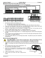
AC Power Source
White
4
4
Black
5
5
Ground
7
7
Awning #1 Motor
Black
Refer to Flag Note 2
Red
White 3
Ground 6
Awning #2 Motor
Black
Refer to Flag Note 2
Red
White 3
Ground 6
#1 Sensor
10’ Cable
“AMD”
#2 Sensor
10’ Cable
“AMD”
Key Pad
25' Cable
DSK
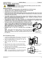
RF Receiver
60” Cable
"EYE" see note 4
Ignition Lockout
60“ Cable
"EYE" see note 4
Green (Ground)
White
Red
Black
1
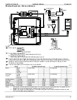
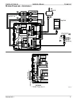
Wire Legend:
2
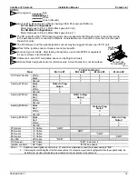
Awnings #1 & #4 shown as LH Motor, Awnings #2 & #3 shown as RH Motor
For LH Motor Configurations:
Motor Red goes to Pin (1); Motor Black goes to Pin (2)
For RH Motor Configurations:
Motor Red goes to Pin (2); Motor Black goes to pin (1)
3
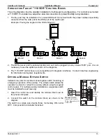
The SO cable from the 110VAC awning motor can only pass directly through a wall, it cannot be laid up
in the wall and must be connected to NM wire or individual wires in conduit no more than 6 inches past
the point of entry.
NOTES:
4
DR016a
5
Wires for the Ignition Lock-Out Sensor are not pin specific.
The RF Reciever and the optional Ignition Lockout may be plugged into any open “EYE” port.
7
6
Cables are 4-wire RJ11 terminated phone cord (straight, no twist)
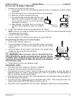
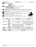
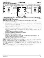
For screw type terminals: After testing connections, use Loctite 29005 or equivalent
to secure screws in terminal block.
8
Terminal block designations are for reference only. Actual boards may not be marked.
Loctite
29005
Screw Type
Terminal Block


