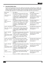
Carbolite MTF 15 Скачать руководство пользователя страница 9


MTF 9/15 


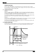
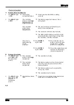
4.11  Stopping the Timer 


To stop the timer at any time while it is running, change the 

StAt

 parameter to 

OFF

. This is the 

same as reducing 

tmr

 to zero. The controller then acts as though at has reached the end of the time 

period. 

4.12  End of Time Period 


Modes 1 and 3: heating stops at the end of timing; the 

m-A

 parameter changes to 

mAn


Modes 2 and 4: heating continues at the end of timing; the 

m-A

 parameter remains at 

Auto


Mode 5: heating starts at the end of the timing period; the 

m-A

 parameter remains at 

Auto

.   


In modes 1 to 4 the alarm message 

EnD

 flashes on the display at the end of  timing; the 

StAt


parameter remains at run.  


In mode 5 there is no 

End

 message; the 

StAt

 parameter changes to 

OFF

 at the end of timing. 

4.13  Cancelling the Alarm 


To acknowledge (cancel) the 

EnD

 alarm, press Page and Scroll together; the 

StAt

 parameter 

changes to 

OFF

.  


Alternatively the alarm may be cancelled by directly changing the 

StAt

 parameter from 

run

 to 

OFF

4.14  User Calibration 


The controller is calibrated for life at manufacture against known reference sources, but there may 
be sensor errors or other system errors. User calibration allows compensation for such errors, and 
the 2132 allows for a user 2-point calibration. This setting is password protected to avoid 
accidental alteration. 

 Page 

to 

iP

, scroll to 

CAL.P

, and use Up 

S

 to alter the password. The password is 

3

. If the correct 

password is entered, the display shows 

PASS

. Scroll to 

CAL

 and use 

T

 or 

S

 to observe the setting 

FACt

 (factory values, as manufactured) or 

USEr

 (user values). Change to 

USEr


NOTE: before checking the calibration of the controller, or of the complete system, remember to 
reset the 2132 to factory calibration values by setting the 

CAL.P

 parameter to 

FACt


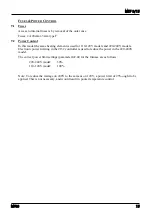
To enter a user calibration, scroll to each or the following parameters in turn and set the desired 
values. 


Pnt.L


low temperature for which an offset is to be entered 


OFS.L


offset value for the low temperature 


Pnt.H


high temperature for which an offset is to be entered 


OFS.H


offset value for the high temperature 


Example: the controller reads 3°C low at 400°C, and 5°C low at 1000°C. The parameter values 
should be 

Pnt.L

=

400

OFS.L

=

3

Pnt.H

=

1000

OFS.H

=

5


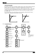
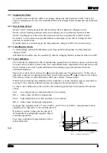
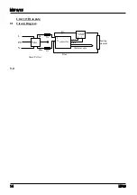
Negative or positive values can be entered: if 
the controller is reading high, negative offsets 
would be appropriate. 


Fig 4 gives a graphical representation of the 2-
point calibration. 


5.0 

MF09 

Содержание MTF 15

Страница 1: ...supply CONTENTS section page 1 0 Symbols Warnings 2 2 0 Installation 3 3 0 Operating Instructions 4 4 0 Controller Operation 5 5 0 Maintenance 10 6 0 Repairs Replacements 11 7 0 Fault Analysis 13 8 0...

Страница 2: ...s Heat Light the adjacent light glows or flashes to indicate that power is being supplied to the elements 1 2 Warning Symbols DANGER of electrical shock read any warning printed by this symbol DANGER...

Страница 3: ...A C supply with earth ground The supply may be Live to Neutral non reversible Live to Neutral with reversible plug or Live to Live The voltage or range of voltages on which the furnace may be operate...

Страница 4: ...e at high temperature when not required The maximum temperature is shown on the furnace rating label and on the back page of this manual Materials such as waxes case hardening compounds melting fluxes...

Страница 5: ...in the Navigation Diagram To return to the Home list at any time press Page and Scroll 4 together or wait for 45 seconds The Down T and Up S keys are used to alter the setpoint or other parameter valu...

Страница 6: ...nd fig 2 indicate the possible difference between running without and with a ramp to setpoint value depending on the load and the value used 4 6 Navigation Diagram OP Hi SPrr m A w SP Home List Input...

Страница 7: ...The timer starts timing immediately At the end of the timing period control switches off i e goes into Manual to allow cooling and End flashes on the display On during the timing period Off from the...

Страница 8: ...ameter changes to run Note that the tmr display shows 0 zero during the last minute of timing and also shows 0 when the time has expired The timer light indicates whether timing is still in progress M...

Страница 9: ...rrors or other system errors User calibration allows compensation for such errors and the 2132 allows for a user 2 point calibration This setting is password protected to avoid accidental alteration P...

Страница 10: ...hroughout the world We also sell spares by mail order A telephone call or fax often enables a fault to be diagnosed and the necessary spare part despatched Each furnace has its own record card at Carb...

Страница 11: ...ulletin No 11 and the UK Health and Safety Executive Guidance Note EH46 We can provide further information on request Alternatively our service division can quote for any repairs to be carried out at...

Страница 12: ...beads When refixing the wrapped element position the beads just above edge of the metal channel to maximise the clearance between the outer case and the wires 6 6 Solid State Relay Replacement The so...

Страница 13: ...ghts glowing on the controller The SUPPLY light is ON The controller may be faulty or not receiving a supply due to a faulty switch or a wiring fault The SUPPLY light is OFF Check the supply fuses and...

Страница 14: ...MTF 9 15 CIRCUIT DIAGRAM 8 1 Circuit Diagram heating element thermocouple 2A 2A Re d Re d Blue Blue L N PE controller L N filter SSR pink grey 2 1 3 4 Green Yellow 9 0 14 MF09...

Страница 15: ...nd 220 240V models Electronic power limiting in the 2132 controller is used to reduce the power in the 220 240V model The correct power limit settings parameter OP Hi for the furnace are as follows 22...

Страница 16: ...l 41 41 541 5877 Fax 41 41 541 5878 Email General Information Sales info kesn ch Accounts Department accounts kesn ch USA O ce 233 Rogue River Highway 425 Grants Pass Oregon 97527 5429 USA Tel 1 503 2...

Отзывы: