4
REPLACING PLANER KNIVES
1.
Remove top cover and dust chute.
2.
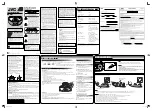
Loosen 2 screws Fig. 5 (A) and pivot motor
assembly for ward.
3.
Loosen the screws that hold knife locking bar in
place Fig. 6 (B).
4.
Remove all 3 knives, locking bars and screws from
the cutterhead.
5.
Clean the knife slots and bars,removing all traces
of sawdust and resin.
6.
Replace the locking bars and put all three new
knives in position, tightening the locking bar
screws just enough to prevent the knives from
falling out.
7.
To adjust the height of the knives, you will need
the knife setting gauge Fig. 7 (C). Place it on top of
the cutterhead.
8.
To adjust the height of the blades, turn the allen
key screws located at each end of the knife locking
bars Fig. 7 (E) anticlockwise to lower and clockwise
to raise them. The tip of the blades should just
brush the bottom of the setting gauge, this should
be even along the length of the blade.If there is no
movement of the blade when the adjustment
screws are moved, the screws holding the knife
locking bars in place may be too tight to allow the
blades to move.
9.
All three blades must be the same height, if not,
this will result in end snipe. (A dip at the end of
the board.)
10.
Tighten the locking bar screws evenly. Double
check that all of them on all three blades are tight.
11.
Replace top cover and dust chute and return
motor to correct position.
ADJUSTING HEIGHT OF CHIP DEFLECTOR
1.
Access the inside of planer (see previous
instructions).
2.
Loosen of f the three slotted screws Fig. 7 (D)
that hold the nylon chip breaker in place.
3.
Slide the chipbreaker down until it is about
0.5mm from the full arc of the blades in the
cutter block.CHECK THAT THE CHIP BREAKER
DOES NOT MAKE CONTACT WITH THE BLADES.
4.
Tighten the screws and replace the top cover and
dust chute.
FEED ROLLER SPEED CONTROL
Your planer has 2 feed roller speeds 16 fpm and
30 fpm. For general purpose planing on softer woods,
the faster speed is suitable, but for hard timbers, the
slower feed rate is more ef fective. A slower speed puts
less strain on the motor. A slower feed rate will also
give a better finish as there will be more cuts per inch.
When changing the setting of the feed roller speed Fig.
8 (A) it is essential to have the machine running. Pull
the speed control lever all the way out for the slow
speed, 16fpm. The middle position is neutral,and push-
ing the lever all the way will give a feed roller speed of
30fpm.
A
A
A
B
D
C
D
D
E
E
Fig. 5
Fig. 6
Fig. 7
Fig. 8
Содержание CTJ-381
Страница 2: ...15 PLANER MODEL CTJ 381 INSTRUCTION MANUAL...
Страница 10: ...9...
Страница 11: ...10...
Страница 12: ...11...
Страница 13: ...12...
Страница 14: ...13...
Страница 15: ...14 ALL ELECTRICAL WORK SHOULD BE UNDERTAKEN BY A LICENSED ELECTRICAL CONTRACTOR...
Страница 16: ...15...


