background image

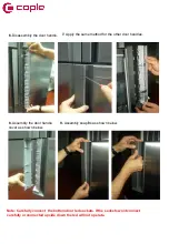
1.

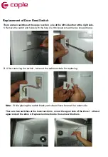
Remove the switch and holder with the help of a thin tipped screwdriver as showed below.

2.

After removing the switch , take out the cable sockets for replacing.

Note:  

While placing the switch black part should have been at the outer side. 

There are two switches at the upper section , one at the left side other at the right side.


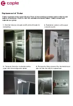
Replacement of Door Reed Switch 

There are two switches at the lower sections , one at the upper side of the Zone 1  other at 
upper side of the Zone 2. Replacement method is the same with others.


Содержание CAFF45GM

Страница 1: ...CAFF45GM Caple 4 door Freestanding Fridge Freezer Technical Manual ...

Страница 2: ...CAFF45GM Caple 4 door Freestanding Fridge Freezer ...

Страница 3: ...CAFF45GM Caple 4 door Freestanding Fridge Freezer ...

Страница 4: ...CAFF45GM Caple 4 door Freestanding Fridge Freezer ...

Страница 5: ...CAFF45GM Caple 4 door Freestanding Fridge Freezer ...

Страница 6: ...CAFF45GM Caple 4 door Freestanding Fridge Freezer ...

Страница 7: ...0 RV2 41A 42111087 CRISPER 910 RIGHT TRANS WH GRAY 41B 42111088 CRISPER 910 LEFT TRANS WH GRAY 42 37029727 CRISPER PRF SRGF 910 DARKINX 58 42052644 KICK PLATE HOLDER GK S W 60 42166054 KICK PLATE 910 DARK 62 42130996 ICE TRAY COVER 366 RV1 S W 70 35001678 SCREW KA 40 14 YSB R F INOX 87 35003056 FRONT WHEEL GR 88 42126562 TOP HINGE C 910 RIGHT DARKGRAMATVER RV3 88A 42126561 TOP HINGE C 910GR RIG DA...

Страница 8: ...2027387 SUP CAB GR ZBH1122CY 5UF 2 5M UK 210 32007439 POWER CORD 2 5m ENG 211 32020696 OVER L GR ZBH1122CY B68 120 QP3 12A 211B 42177882 COMP COVER JIAXIPERA 24 01 59 212 32010690 CAPACITOR 5UF 400V P2 TIRNAK 6 3 0 8 213 37022312 TRUSS ST 4 12 SPECIAL14 C 214 42099227 EVAPORATING TRAY GR 915 KAR 215 37029010 DRYER XH9 0 40MM 10GR I C 3 1 216 20020023 COMP FIXING BRACKET 217 32019159 COMP ZBH1122CY...

Страница 9: ... S W 428 42162194 R MULTI FLOW GR 916 NEW MI 429 42108053 R MULTI FLOW 916 NEW 431 32028874 TUR FAN MOT DC 92 92 25 T92T12MS5A7 5NDC 432 47011757 MOTOR FAN KAU 916 NEW 433B 32010909 SENSOR STANDARD R6K 70MM SINGLE 449 42033244 R MULTIFLOW CAP 640 S W 459 42077845 F DOOR GASKET 910 VFGRI 460 42077799 R DOOR GASKET 910 VF GRAY 498A 42148857 D HANDLE FLX GR TOP S 868 CLSIX 498B 42148858 D HANDLE FLX ...

Страница 10: ...GRAY DARK 753 37017352 CRIS RAIL OUT RIGHT 910 753B 42074180 FRZ BASKET ROLLER RAIL TOP RIGHT 910 753C 42074190 FRZ BASKET ROLLER RAIL BOTTOM RIGHT 910 754 37017353 CRIS RAIL OUT LEFT 910 754B 42074186 FRZ BASKET ROLLER RAIL TOP LEFT 910 754C 42074188 FRZ BASKET ROLLER RAIL BOTTOM LEFT 910 800 42110561 TRIZ BAR CABINET GR 910 S W RV1 801 37021419 CHILLER RAIL ASSEMBLY SHEET FRONT 802 37017960 CHIL...

Страница 11: ...V 910 COOLDI 828 37026946 DOOR HANDLE SUPPORT PART 910 GLXY SHEET 829 42146858 DOOR HANDLE FLX CAP CLS 831 42074039 HINGE SOCKET HOUSING 910 S W 832 42081639 HINGE HOUSING COVER 910 S W 833 32017147 LED STRIP R INSIDE DOOR GR 910 834 42132624 INSIDE DOOR LED COVER 910 MILKY PS 835 42137248 F GLASS SHELF STOPPER RV1 910 1026 40007341 COMP RUBBER DANFOSS 47008408 DOOR MAGNET ...

Страница 12: ...1 CUSTOMER SUPPORT WHITE GOODS 916 FRENCH DOOR SEPTEMBER 2015 CIRCUIT DIAGRAM ...

Страница 13: ...CAFF45GM Service Manual ...

Страница 14: ...ne 2 1 Fridge compartment shelves 2 Chiller breakfast compartment 3 Crispers 4 Cheese Butter shelf covers 5 Cheese butter shelf 6 Door shelves 7 Eggcups 8 Door bottle shelves 9 Iceboxes 10 Freezer Cooler top baskets 11 Freezer Cooler bottom baskets 12 Adjustable feet ...

Страница 15: ...ltage warning 15 Alarm Service Recall SR 16 Screensaver button 17 Zone 2 Right freezer button 18 Mode button 19 Cooler button 20 Qdrink mode button 21 Zone 1 Left freezer button The values on the screen indicate temperature values specified by the consumer Standby display is protected against faulty contact Therefore you must touch any key on the display before you take any action After 2 seconds ...

Страница 16: ...ing light 5 Super freezing light 6 Qdrink alarm counter 7 Vita Store mode 8 Economy mode 9 Holiday mode 10 Qdrink light 11 Night sensor 12 Child lock 13 Dealer Demo mode 14 Low voltage warning 15 Alarm 16 Screensaver button 17 Zone 2 Right freezer button 18 Mode button 19 Cooler button 20 Qdrink mode button 21 Zone 1 Left freezer button 22 Door Light On 23 Door Light Off ...

Страница 17: ...epresented by an umbrella and sun If you will go to holiday for a long time and during this time if you will not use cooler compartment you may activate this mode To switch the appliance to holiday mode you should just press mode button until holiday symbol and H light comes on Quick freezing SF SUPERFREEZE You should press on zone1 or zone2 buttons until sf letters are displayed on the display On...

Страница 18: ...7 8 Celsius temperature values Freezer Cooler 2 ZONE 2 It is temperature setting button for bottom right compartment By pressing zone 2 button freezing value of bottom right part can be set as 16 17 18 19 20 21 22 23 24 Celsius temperature values If you do not want to use bottom right part as cooler press zone 2 button for 3 seconds to switch to this mode and set to 2 3 4 5 6 7 8 Celsius temperatu...

Страница 19: ... a Freezer Compartment as Cooler Compartment Based On Demand The bottom right and left compartments on the appliance can be used either as freezer and cooler Preferably you need to press zone 1 button for 3 seconds to use bottom left part as cooler or zone 2 button for 3 seconds to use bottom right part as cooler Important If Zone1 Zone2 compartment will be converted from freezer to cooler You sho...

Страница 20: ...ould leave the door close for 4 hours Then food will be placed in the relevant compartment Baskets and or shelves removed from the compartment should be re fitted Note VitaStore mode shouldn t be activated if Zone 1 is used as freezer Foods should not be put in front of the fan VitaStore keeps fruits and vegetables fresh and helps vitamin and nutritional values of fruits and vegetables to protect ...

Страница 21: ... not place much food inside it in this period 5 minute delaying function is applied to prevent damage to the compressor of your fridge when you take the plug off and then plug it on again to operate it or when an energy breakdown occurs Your fridge will start to operate normally after 5 minutes Your fridge is designed to operate in the ambient temperature intervals stated in the standards accordin...

Страница 22: ...pen and close Zone 2 door for 3 times Then appliance will go on demo function and Door light open Symbol will light during the mode Canceling Demo mode For cancelling Same operation will be used If user will push q drink button continuously During this time open and close Zone 2 door for 3 times demo function will be cancelled When appliance is Demo mode if plug is removed or there is an electrici...

Страница 23: ...Flow of Air ...

Страница 24: ...ZONE 1 ...

Страница 25: ...COOLER Compartment and ZONE 2 ...

Страница 26: ...Symbols will be OFF Only Alarm symbol will blink during Service Mode If there is no error segments will show nothing except of Alarm symbol If service man pushes Quick Drink button he will be able to choose functions listed next page Functions will be set if service man does not push any other button for 1 sec Service man has 4 functions to select First 4 push of Quick Drink button will activate s...

Страница 27: ...essor_2 is ON 05 will light when Compressor_1 is ON 06 will light when Refrigerator Defrost Resistance is ON 07 will light when R Su Heater is ON 08 will light when Trizbar Heater is ON 09 will light when Refrigerator Frame Heater is ON 10 will light when Aku_1 Heater is ON 11 will light when Balance_1 2 Heater is ON 12 will light empty 13 will light when Refrigerator Air Duct Heater is ON 14 will...

Страница 28: ...ooler button Symbol will be OFF if defrost is canceled manually Appliance will return to initial Service mode reaction If manual canceling of this function is not performed in 30 min Service mode will be canceled Appliance will check if defrost is finished in this 30min It YES appliance will go on from previous set values But if defrost is not finished appliance will go on defrost till it finishes...

Страница 29: ...he way ON will blink If the service man push zone_2 button the valve will change to other side way and part icon which valve gives the way ON will blink Compressor will run during this mode Manual canceling will be done by pushing cooler button Symbol will be OFF and valve return to initial condition Appliance will return to initial service mode reaction ...

Страница 30: ...canceled Appliance will return to initial service mode reaction 5 Push Empty No function is set Sensor Temperature Value Sensor Number Sensor Temperature Value Zone 1 Sensor Number Zone 2 Cooler compartment sensor temp C Sensor 1 Zone 2 sensor temp C Sensor 2 Zone 1 sensor temp C Sensor 3 Zone 2 defrost sensor temp C Sensor 4 Zone 1 defrost sensor temp C Sensor 5 RDS cooler serpantine evap sensor ...

Страница 31: ...After the service mode is activated the display show the error codes as follows if there is any failure USER AND SERVICE MODE ERROR MESSAGES Alarm symbols on display ...

Страница 32: ......
Страница 33: ...unchanged for10 min continuous compressor run and valve position is outlet 1 If Zone 1 and Zone 2 is used as Freezer compartment ERROR DETAILS F sensor 8 C Freezer compartment is not cool enough R sensor 25 C and if Holiday mode is not active Refrigerator compartment is warm R sensörü 8 C Refrigerator compartment is so cool F sensor 8 C and R sensor 25 C and if Holiday mode is not active Freezer a...

Страница 34: ...ool enough For Refrigerator compartment ERROR DETAILS F sensor 8 C Freezer compartment is not cool enough R sensor 25 C and if Holiday mode is not active Refrigerator compartment is warm R sensor 8 C Refrigerator compartment is so cool F sensor 8 C and R sensor 25 C and if Holiday mode is not active Freezer and Refrigerator compartment both are not cool enough NOTE To prevent the wrong alarms this...

Страница 35: ...m 20 hours again from the beginning If door is opened at second or following defrost cycle time two case can be happen If door opened BEFORE 20 hours in this cycle Complete the defrost cycle time to 20hours and Next defrost cycle time will start from 20 hours again from the beginning If door opened AFTER 20 hours in this cycle Immediately start defrost and next defrost cycle time will start from 2...

Страница 36: ...d remove it Fig 3 1 Fig 3 2 1 Unscrew the screws fixing the left and right top hinge cover Fig 1 1 Fig1 2 Open the door about 30 and remove the hinge covers 2 Disconnect the socket connections Fig 2 1 Fig 2 2 Figure 1 1 Figure 1 2 Figure 2 1 Figure 2 2 Figure 3 1 Figure 3 2 ...

Страница 37: ...e 1 To re assembly the doors basically repeat the previous steps backwards Steps 4 3 2 1 Note 2 After installing the upper doors carefully connect the sockets around hinge area Note 3 Three out of Four screw sockets are slotted to let door adjustment Figure 4 1 Figure 4 2 ...

Страница 38: ... piece of tape to cover left right and middle of the bottom sheet as shown at below pictures 2 To remove the kick plate start from the right side an gently release the plastic holder tab Then again gently release the middle tab Replacement of Kick Plate Figure 1 1 Figure 1 2 Figure 2 1 Figure 2 2 Figure 3 1 Figure 3 2 ...

Страница 39: ...Assembly of the Kick plate 1 Check the kick plate holders if damaged replace them with new ones 2 Start mounting from the left side and make sure the tabs on the kick plate are matching with the holders ...

Страница 40: ...ng the Bottom Doors 3 Remove the middle hinge fixing screws with Phillips screw driver 1 Remove the right left bottom door hinge covers with a Phillips screw driver 2 Remove the bottom door handle led sockets ...

Страница 41: ...ted upside down the led will not operate 4 Remove the freezer doors by lifting them up Make sure that the led sockets are not tripping anywhere 5 Remove the bottom hinge screws and take out the bottom hinges Note 1 To re assembly the doors basically repeat the previous steps backwards Steps 5 4 3 2 1 ...

Страница 42: ...1 Remove the upper glas shelf 2 Pull towards the fan motor cover placed on the air duct as shown below 3 Then shift and remove the cover Replacement of Refrigerator Fan Motor ...

Страница 43: ...ng screw and takeout the fan motor 5 Hold and pull the fan motor socket as shoen at the below picture There is a radial type fan used in this product which works with DC 12 Volts Cables Red Cable Blue Cable Black Cable for signal ...

Страница 44: ... motor cover and fan motor as described at previous sections 3 Remove the led lightning sockets located at the left and right side as shown at the below pictures 4 Hold and pull the air duct resistance socket Replacement of Refrigerator Multiflow ...

Страница 45: ... To remove the airduct start to pull from the upper side and release the airduct from the holders 6 Remove the airduct 7 Inner view of the air duct is below In case of any fault at resistance leds or plastic holders replace the whole airduct with grouped code ...

Страница 46: ... fixing screws at the left side 10 Remove the left air duct cover 11 Remove the right air duct cover screw caps with the help of a thin tipped tool 12 Unscrew the fixing screws at the right side 13 Remove the right air duct cover Note To re assembly basically repeat the previous steps backwards ...

Страница 47: ...a screwdriver 3 Unscrew the air duct fixing screws 2 Takeout the rails 1 Remove the fixing screws of drawer rails 5 Pull and take out the air duct cover Replacement of Freezer Multiflow Note To re assembly basically repeat the previous steps backwards ...

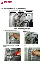
Страница 48: ...ti socket connections 1 Take out the putty on the socket Fan Motor Connector Thermal Fuse Connector Resistance Connector Empty Thermal Fuse Connector 3 Cut off the thermal fuse fixing cable holder 4 Take out the thermal fuse Replacement of ZONE 1 Fin Evaporator Assy ...

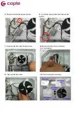
Страница 49: ... 5 Remove the defrost sensor socket 7 Unscrew the fan motor fixing screws 8 Remove the fan motor connector pink connector 9 Take out the fan motor Fan motor rubbers Fan motor Fan motor cover Propeller Fan motor box Screws 10 Fan motor parts are below ...

Страница 50: ...or Thermal Fuse Connector Replacement of ZONE 2 Fin Evaporator Assy Zone 1 Multi socket connections 2 Take out the thermal fuse connector Black connector 1 Take out the putty on the socket 3 Cut off the thermal fuse fixing cable holder 4 Take out the thermal fuse ...

Страница 51: ... 5 Remove the defrost sensor socket 7 Unscrew the fan motor fixing screws 8 Remove the fan motor connector pink connector 9 Take out the fan motor Fan motor rubbers Fan motor Fan motor cover Propeller Fan motor box Screws 10 Fan motor parts are below ...

Страница 52: ...elease it from the holders 3 Carefully flim the evaporator to the left side 4 Slowly pull the tray resistance Not Resistance used at the Zone 1 and Zone 2 are different in terms of power and design they are not interchangeable Replacement of Fin Evaporator Tray Resistance ...

Страница 53: ...connections are described as below 1 Remove the mainboard cover screws placed at the top of the unit and take the Replacement of Main Board Warning Make sure the unit is unplugged Display socket Led socket Ambient socket ...

Страница 54: ...n sockets carefully and remove the mainboard Not All sockets are different on the main board They are not interchangeable 4 Replace the main board 5 Connect the sockets 6 Tidy up the cables place the cover and fix the screws ...

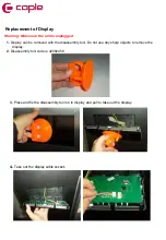
Страница 55: ...se any sharp objects to remove the display 2 Disassembly tool code is 42082456 4 Take out the display cable socket 3 Place and fix the disassembly tool on to display and pull to take out the display Replacement of Display Warning Make sure the unit is unplugged ...

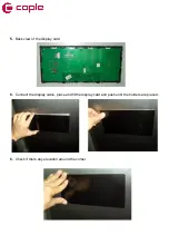
Страница 56: ...5 Back view of the display card 6 Connect the display cable place and fit the display card and push until the holders are placed 6 Check if there any elevation around the corner ...

Страница 57: ...e snapfits on the door handle cover with flat blade screwdriver 2 There are tippings for flat blade screwdriver inside of door handle 3 Disassembly the door handle cover 4 Disassembly the connector of LED 5 Disassembly the screws on door handle ...

Страница 58: ... 6 Disassembly the door handle 8 Assembly the door handle cover as shown below 9 Assembly snapfits as shown below Note Carefully connect the bottom door led sockets If the sockets wont connect carefully or connected upside down the led will not operate ...

Страница 59: ...e of the doors are fixed with double sided tape 4 Remove the led strip sticker with a sharp tool 5 Take out the socket and remove the led strip Replacement of Led Strip inside of the door Note Carefully connect the bottom door led sockets If the sockets wont connect carefully or connected upside down the led will not operate ...

Страница 60: ...at the upper side of the refrigerator cabinet 4 Remove the fixing screws of the mechanism and take out from the body for replacement Replacement of Trizbar Trizbar is placed on the upper left door There are two sliding connection point at the top and bottom of the trizbar There is a DC 12V resistance inside the trizbar Trizbar should have replaced as a group ...

Страница 61: ...ng Note While placing the switch black part should have been at the outer side There are two switches at the upper section one at the left side other at the right side Replacement of Door Reed Switch There are two switches at the lower sections one at the upper side of the Zone 1 other at upper side of the Zone 2 Replacement method is the same with others ...

Страница 62: ...gerator Sensor is placed at the inner left side of the refrigerator section Replacement of Sensors 1 Remove the refrigerator sensor cover by pulling forward 2 Remove the sensor by hand and remove the sensor connector 1 Remove the refrigerator sensor cover by pulling forward 2 Remove the sensor by hand and remove the sensor connector ...

Страница 63: ...ard 2 Remove the sensor by hand and remove the sensor connector 1 Remove the refrigerator sensor cover by pulling forward 2 Remove the sensor by hand and remove the sensor connector Zone 2 sensor is placed at the inner left back side of Zone 2 Note Make sure that cover holder details not broken while removing placing ...

Страница 64: ...iller upwards while pushing the telescopic rail downwards to release the holder Left Right 3 Push the chiller upwards while pushing the telescopic rail downwards to release the holder 4 After releasing the chiller from the front holders pull the chiller Chiller dismounting ...

Страница 65: ...5 Release the chiller from the rail holders by pulling it towards Left Right Front holder Front holder Back holder Back holder Details of front back holders ...

Отзывы: