background image

Recheck  the  right  side  and  then  lock  the  adj.  screw  with  the  nut 

provided.  The  most  accurate  method  of  setting  the  infeed  roll  is 

with the bed and feed roll gage. Find the low point of the knife arc 

to  the  end  of  the  gage  then  set  the  infeed  roll  to  0.062  for 

sectionalized  infeed rolls below the zero point. It is  important that 

the  setting  on  both  sides  of  this  infeed  roll  be  close  to  the  same 

height to help avoid skewing of the material as it is fed through the 

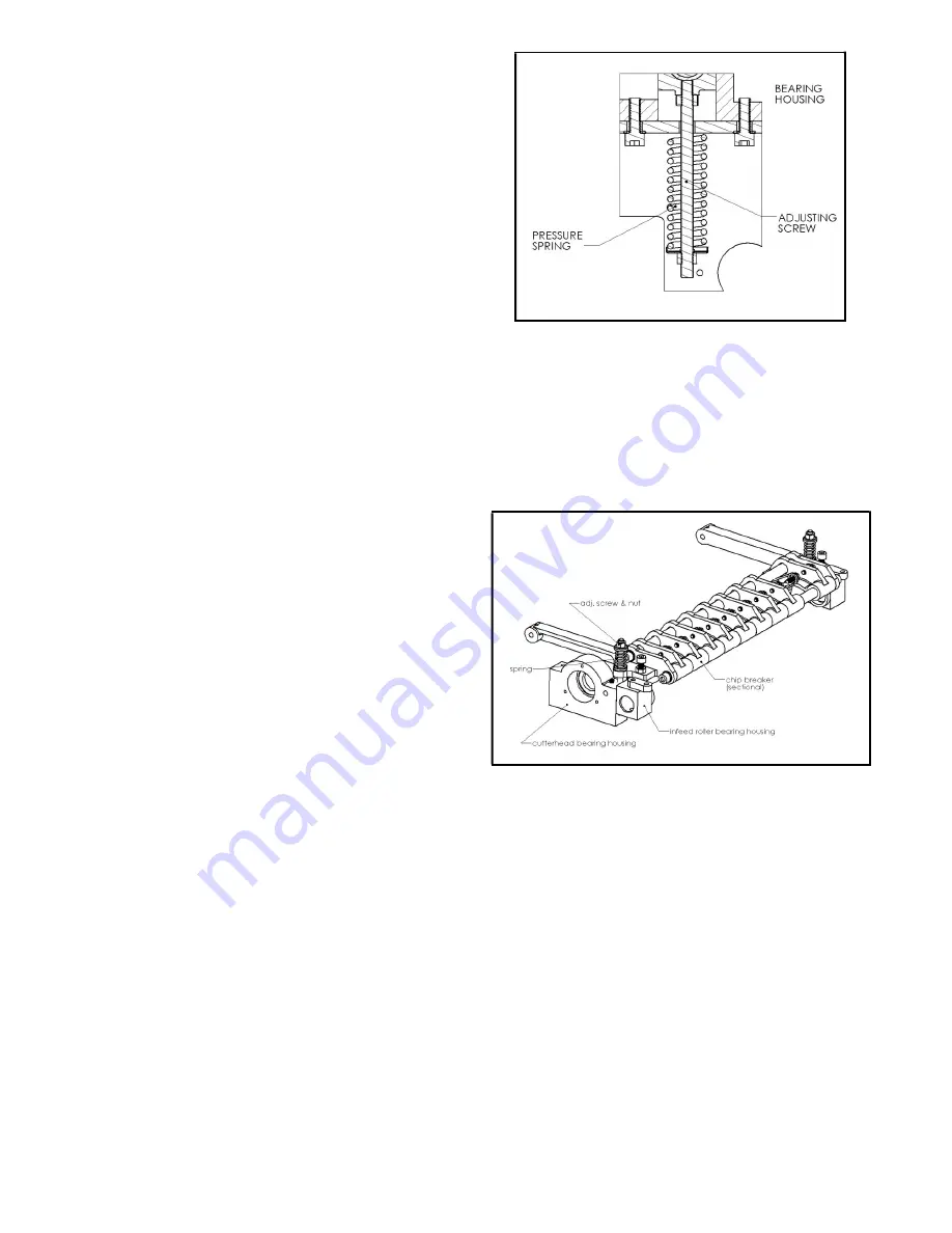
machine.  Infeed  roll  pressure  is  controlled  by  springs  and  is 

adjusted  by  use  of  screws  located  under  the  side  panels  (Fig.  8) 

pressure  should  be  slightly  higher  on  the  drive  side  to  help  avoid 

skewing of board as it feeds through. 


Fig. 8 

 
5-3 Chip Breaker: 

The sectionalized chip breaker is constructed of 2"(50.8mm) wide spring-loaded sections mounted on a bar. Each sation has approximately 

1/4"(6.4mm) independent yield. The functions of the chip  breaker are to help avoid splintering out of the wood, to break chips into small 

pieces,  to  help avoid board bounce  thinner  board bounce  on  thinner boards,  to direct  the flow  of chip out of  the machine.  And  to permit 

multiple boards surfacing up to 1/4"(6.4mm) difference in thickness on the sectionalized type. 


The  chip  breaker  in  its  free  position  should  1/32"  (0.8mm)  below 

the cutting arc of the knives, the same as the infeed roll, using the 

same method as indicated for the infeed roll, remove the cover over 

the  top  scction  of  the  planer,  adjust  the  chip  brcaker  free  position 

using a 2 x 4 gage block and shop scale of the proper thickness and 

adjusting screws at each end. It is important that each end be close 

to the same height to help avoid skewing of the material as it is fed 

through the machine (Fig. 9) 

(Caution:  A  chip  breaker  set  too  low  may  prevent  stock  from 

feeding into the machine.) 


Fig. 9 


5-4 Outfeed Roll: 

The outfeed roll is smooth and of one-piece construstion to help avoid marring the finished surface of the material being cut. Its function is to 

continue to feed the material through the machine after it leaves the infeed roll. The correct free position setting is 1/32" (0.8mm) below the 

arc of the cutterhead knives. Using the gage block or a finished 2 x 4 on edge with a 1/32" (0.8mm) shop scale on top under the cutterhead, 

raise the table and rock the cutterhead to establish the low point of the knife arc. Remove the scale and position the gage or 2 x 4 under the 

right side of the outfeed roll. Raise or lower its right hand bearing support with the adj. screws provided (Fig.8) to a light drag fit. Move the 

gage or 2 x 4 under the left hand end and adjust in the same way. The most accurate method of setting the outfeed roll is with the bed and 

feed roll gage. Zero the gage to the low point of the cutterhead arc and set each end of the outfeed roll to .031(0.787mm) below the zero on 

both sides. Lock the adj. screws with the nuts provided. Out feed roll presure is controlled by springs and is adjsuted by use of screws located 

under the side panels (Fig. 8). Unblanced pressure can result in skewing of the board as it feeds through. 

Содержание P24HV

Страница 1: ...w cantekamerica com Please ensure you have your serial number available when contacting us for parts or service Cantek America Inc 1 888 982 2683 Parts sales cantekamerica com Service service cantekam...

Страница 2: ...3 3 PREPARATION FOR OPERATION 3 4 3 1Inspection 3 3 2Power Source wiring 3 3 3Lubrication 3 3 4Safety 3 4 4 MAINTENANCE 4 4 1General maintenance 4 4 2Lubrication 4 5 MACHINE ADJUSTMENT 5 10 5 1 Work t...

Страница 3: ...rcle 84mm 3 5 16 Speed 4800RPM Table Size Width 660mm 25 1 4 Length 713mm 28 Feed Rolls Infeed sectional 76mm one 3 Outfeed solid 60mm one 2 3 8 Table roll solid 68mm two 2 11 6 Feed Rate 8MPM one spe...

Страница 4: ...2 1 3 OPERAING PARTS 1 P24 01 BASE DEPT 2 P24 02 WORK TABLE 3 P24 03 UPPER DEMP 4 P24 04 GEAR DEPT 5 P24 05 ELECTRIC DEAR 6 P24 06 SIDE FRAME DERT...

Страница 5: ...ng for a short period of time to check that all powered functions are operating properly 3 3 Lubrication Supply oil to all the necessary position 3 4 Safety A Grounding of the planer Make certain that...

Страница 6: ...eadcomes to a complete stop before lowering the table to remove the board Never lower the table with the power on and the stock still in the machine A kickback can occur which could cause a severe or...

Страница 7: ...Check with knife gage to insure knives have the same protrusion form the cutterhead arc end to end and that each knife is the same Place a 5 x5 127mm x 127mm gage block Fig 4 and shop scale to be use...

Страница 8: ...ial into the machine It is a corrugated roll and when sectionalized is made up of one inch 25 4mm wide sections with 1 4 6 4mm movement in each section to accommodate multiple board surfacing In addit...

Страница 9: ...ion of the planer adjust the chip brcaker free position using a 2 x 4 gage block and shop scale of the proper thickness and adjusting screws at each end It is important that each end be close to the s...

Страница 10: ...a test cut Fig 10 5 6 Table rolls Two table rolls are provided on the planer to help reduce the friction of the stock on the table as it feeds through the machine The required height of table rolls ar...

Страница 11: ...o prevent pitch buildup 5 8 Knife Installation Knife installation on planer can be a difficult and exacting process If the knives are not to be jointed and ground end to end and knife to knife relatio...

Страница 12: ...nife have been installed recheck all gib screws to be sure they are tight Loose gib screws can result in knives being thrown out of the cutterhead causing severe damage to the machine and possible ser...

Страница 13: ...e 1 4 C007001 Gib 2 5 G002002 Elevator Bolt Assembly 1 6 S284008 Spring Washer 10 2 4 7 S137030 Hex Head Screw M10 P1 5 4 8 C067064 Sprocket 1 9 C015017 Support Handle 1 10 S282107 Washer 6 4 3 11 S28...

Страница 14: ...12 PARTS LIST NO PARTNO DESCRIPTION Q TY 1 C015094 Plate 1 2 T016008 Level Gear 1 3 S284007 Spring Washer 8 2 10 4 S202025 Hex Socket Head Screw M8 P1 25 10 5 T003003 Level Screw 2...

Страница 15: ...13 PARTS LIST NO PARTNO DESCRIPTION Q TY 1 C009021 Support 1 2 P051001 Brass Bearing 1 3 S043004 Thrust Bearing 1 4 C035001 Shaft 1 5 C028001 Gear 1 6 S267512V Spring Pin 1 7 C037002 Collar 1...

Страница 16: ...14 PARTS LIST NO PARTNO DESCRIPTION Q TY 1 C015015 Support 2 2 P051001 Brass Bearing 2 3 C039026 Shaft 1 4 C028002 Bevel Gear 2 5 S267510V Spring Washer 3 6 C067018 Sprocket 1...

Страница 17: ...t Screw M8 P1 25 2 9 C046010 Shaft 1 10 C049011 Short Plate 1 11 C049010 Long Plate 1 12 C051022 7L Bushing 4 13 S282108 Washer 8 4 4 14 S284007 Spring Washer 8 2 4 15 S202020 Hex Socket Head Screw M8...

Страница 18: ...16...

Страница 19: ...12 6 T004051 Motor Assembly 1 7 S277006R Nut M6 P1 0 2 8 C034031 Bolt Motor 1 9 C051080 Collar Handwheel 1 10 P025155G Handwheel 1 11 S213014 Fixed Screw M8 P1 25 1 12 P028014N Knob 1 13 P031006 Star...

Страница 20: ...HP 7 5KW L 1 2 C064140 Pulley 1 3 S214025 Fixed Screw M10 P1 5 2 4 C063054 Support Motor 1 5 S282011 Washer 10 5 3 6 S284008 Spring Washer 10 2 6 7 S137045 Hex Head Screw M10 P1 5 3 8 S273042 Nut M10...

Страница 21: ...mbly 1 10 S273010R Nut M10 P1 5 14 11 S203040 Hex Socket Head Screw M10 P1 5 6 12 C060007 Spring 2 13 C053022 35 Washer 4 14 T011007 Outfeed Roller Assembly 1 15 C060012 Spring 2 16 C042035 Rear Press...

Страница 22: ...20...

Страница 23: ...er Left Housing 1 5 C009054 Support Bearing 1 6 C053069 Washer 11 1 7 C034134 Hex Head Screw M10 P1 5 1 8 C010027 Cover Right Housing 1 9 S284006 Spring Washer 6 1 6 10 S135020 Hex Head Screw M6 P1 0...

Страница 24: ...C042009 Chipbreaker 12 2 C060008 Spring 12 3 S282010 Washer 8 4 12 4 S136025 Hex Head Screw M8 P1 25 12 5 C048037 Shaft 2 6 C015095 Support L 1 7 S284009 Spring Washer 12 2 4 8 S204030 Hex Socket Hea...

Страница 25: ...23 PARTS LIST NO PARTNO DESCRIPTION Q TY 1 C046128 Rod 1 2 C052077 Bushing 2 3 C045012 Finger 46 4 C052014 Bushing 45...

Страница 26: ...023 Bushing 2 5 S213001 Set Screw M8 P1 25 4 6 C009017 Bearing Block R 1 7 C009049 Bearing Block L 1 8 P051002 Brass Bearing 2 9 C067014 Sprocket 1 10 S003073 Key 1 11 S282113 Washer 10 5 1 12 S284008...

Страница 27: ...Copper Bearing 1 3 C009049 Left Support Copper Bearing 1 4 P051002 Copper Bearing 2 5 C067015 Sprocket 1 6 S003073 Key 1 7 S282113 Washer 10 5 1 8 S284008 Spring Washer 10 2 1 9 S137620 Hex Head Scre...

Страница 28: ...S203025 Hex Socket Head Screw M10 P1 5 2 7 S277010R Nut M10 P1 5 2 8 T013003 Small Sprocket Assembly 1 9 S137030 Hex Head Screw M10 P1 5 1 10 T013027 Table Roller Assembly 2 11 C020003 Datum Plate 2...

Страница 29: ...28 PARTS LIST NO PARTNO DESCRIPTION Q TY 1 T014002 Gear Box Assembly 1 2 T015017 Belt Shaft Assembly 1 3 S284007 Spring Washer 8 2 3 4 S136025 Hex Head Screw M8 P1 25 3...

Страница 30: ...29003 Large Gear 1 2 C039003 Gear Shaft 1 3 S137016 Hex Head Screw M10 P1 5 4 4 S026206ZZ Ball Bearing 1 5 C031001 Gear Housing 1 6 S026203ZZ Ball Bearing 1 7 C009022 Gear Housing Cover 1 8 C067016 Sp...

Страница 31: ...PTION Q TY 1 C009005 Housing Bearing 1 2 S026204ZZ Bearing 1 3 S026205ZZ Bearing 1 4 C029011 Gear Shaft 1 5 C064141 Pulley 1 6 S003079 Key 1 7 S282109 Washer 8 2 1 8 S284007 Spring Washer 8 2 1 9 S136...

Страница 32: ...31 PARTS LIST NO PARTNO DESCRIPTION Q TY 1 C039004 Sprocket Shaft 1 2 C067017 Sprocket 1 3 S026203ZZ Ball Shaft 1 4 S298125 C Ring 1 5 S298008 C Ring 1...

Страница 33: ...PARTS LIST NO PARTNO DESCRIPTION Q TY 1 C040039 Roller 1 2 C009008 Support 2 3 S026205ZZ Ball Bearing 2 4 S298131 C Ring 2 5 C051020 Collar 2 6 S273042 Nut M10 P1 5 6 7 S137320 Hex Head Screw M10 P1 5...

Страница 34: ...1001 Brass Bearing 1 3 C052016 Bushing 1 4 S282111 Washer 10 5 2 5 S137035 Hex Head Screw M10 P1 5 1 6 C049018 Linked Plate 1 7 C015030 Linked Support 1 8 C051024 10L Bushing 1 9 S284008 Spring Washer...

Страница 35: ...P1 0 28 15 C023051 Support Dust Hood 1 16 C077024 Dust Hood 1 17 C073059 Cover Motor 1 18 S284006 Spring Washer 6 1 4 19 S201120H Hex Socket Head Screw M6 P1 0 4 20 C073017 Cover Right Base 1 21 C0730...

Страница 36: ...35...

Страница 37: ...Head Screw 5 32 32NC 2 8 P074003P18G N Series AC Contactor 1 9 S312003 Box Terminate Seat 1 10 S282105 Washer 5 3 2 11 S225010 Round Head Screw M5 P0 8 4 12 S273039 Nut M5 P0 8 2 13 S313001 Terminate...

Страница 38: ...37...

Страница 39: ...96006 Allen Wrench M5 1 2 S296007 Allen Wrench M6 1 3 S296008 Allen Wrench M8 1 4 S290072 Open End Wrench 10x14 1 5 S290074 Open End Wrench 17x19 1 6 S292304 T Type Allen Wrench 4 0mm 1 7 P028014N Kno...

Страница 40: ...39 PARTS LIST NO PARTNO DESCRIPTION Q TY 1 C057008 Handle Adjusting Plate 1 2 C057009 Adjusting Plate 2 3 S298050 C Ring 2...

Отзывы: