background image

6

6

Installation

Installation

6-2

6-2

Installation > Points to Note at Installation

Installation > Points to Note at Installation

How to Check this Installation Procedure

When Using the Parts Included in the Package

A symbol is described on the illustration in the case of using the parts included in the package 
of this product.

 Packaged Item

Symbols in the Illustration

The frequently-performed operations are described with symbols in this procedure.

Connector

Disconnect

Screw

Tighten

Remove

Connect

Secure

Free

Harness

Push

Insert

Plug in

Turn on

Sound Check

Check

Visual Check

Claw

Remove

Checking instruction

F-6-1

F-6-2

Product Name

Safety regulations require the product's name to be registered. In some regions where this 
product is sold, the following name may be registered instead.
•  F630812

Check Item when Turning OFF the Main Power

Check that the main power switch is OFF.
1) Turn OFF the main power switch of the host machine.
2) Be sure that Control Panel Display and Main Power Lamp are both turned OFF, and then 

disconnect the power plug.

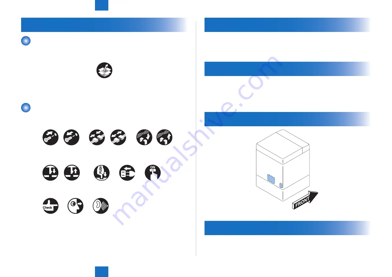
Installation Outline Drawing

Points to Note at Installation

Install this equipment after installing the Super G3 FAX Board. 

F-6-3

Содержание Super G3 FAX board-AL1

Страница 1: ...6 5 4 3 2 1 Super G3 2nd Line FAX Board AL1 Service Manual October 24 2012 Revision 0 Product Outline Technology Parts Replacing and Cleaning Error Code Service Mode Installation ...

Страница 2: ...information as the need arises In the event of major changes in the contents of this manual over a long or short period Canon will issue a new edition of this manual The following paragraph does not apply to any countries where such provisions are inconsistent with local law Trademarks The product names and company names used in this manual are the registered trademarks of the individual companies...

Страница 3: ...switch closing the front door and closing the delivery unit door which results in supplying the machine with power 2 In the digital circuits 1 is used to indicate that the voltage level of a given signal is High while 0 is used to indicate Low The voltage value however differs from circuit to circuit In addition the asterisk as in DRMD indicates that the DRMD signal goes on when 0 In practically a...

Страница 4: ...E 5 16 Contents Overview 5 16 Setting of Printer Functions PRINTER 5 17 Setting of Bit Switch SSSW 5 17 Setting of Numeric Parameter NUMERIC Param 5 18 Initialization of Set Value CLEAR 5 19 Overview 5 19 Test Mode TEST 5 20 Outline 5 20 MODEM Test 5 21 Function Test 5 24 Service Report REPORT 5 25 System Data List 5 25 System Dump List 5 25 Error Transmission Report 5 26 6 Installation How to Che...

Страница 5: ......

Страница 6: ...1 1 Product Outline Product Outline Product Outline Specifications ...

Страница 7: ...Transmission original size A3 A4 A4R A5 A5R B4 B5 B5R LTR LTRR LGL 11x17 STMT STMTR ADF double sided originals accepted Scanning line density Standard 200 x 100 dpi 8 dots mm x 3 85 lines mm Fine 200 x 200 dpi 8 dots mm x 7 7 lines mm Super Fine 200 x 400 dpi 8 dots mm x 15 4 lines mm Ultra Fine 400 x 400 dpi 16 dots mm x 15 4 lines mm Halftone 256 gradations Recording unit maximum reception size ...

Страница 8: ...2 2 Technology Technology Technology Basic Construction Controls ...

Страница 9: ... highly functional multi function fax machine As for image transmission speed it is capable of communicating at 33 6 kbps max thanks to a modem for V 34 which comply with ITU T standard FAX lines can be added to the existing FAX unit for one line Super G3 FAX board AL1 FAX unit FAX line Model name Configuration 1 2 3 4 Super G3 FAX board AL1 for one line Yes Super G3 FAX board AL1 Super G3 2nd Lin...

Страница 10: ...ne the main controller in the machine controls the G3 FAX PCB in the FAX unit A FAX control program is loaded in the G3 FAX control PCB for this product and therefore the FAX unit executes FAX communication control FAX interface G3 FAX PCB Main controller 1 Modular PCB off hook detect PCB FAX unit for one line Copier Speaker G3 FAX controller PCB Modular PCB FAX unit for 2 lines F 2 1 ...

Страница 11: ...3 3 Parts Replacing and Cleaning Parts Replacing and Cleaning Parts Replacing and Cleaning Parts Replacing and Cleaning ...

Страница 12: ...g 3 2 3 2 Parts Replacing and Cleaning Parts Replacing and Cleaning PCBs Parts Replacing and Cleaning Parts Replacing and Cleaning PCBs Parts Replacing and Cleaning PCBs Perform removal in reverse order of the procedures described in the section of Installation ...

Страница 13: ...4 4 Error Code Error Code Overview User Error Code Service Error Code ...

Страница 14: ... Hz in response to the DIS signal from the other party Bit6 1 to cause the machine to send a 1850 Hz tonal signal if bit 5 is set to 1 0 to cause the machine to send a 1650 Hz tonal signal if bit 5 is set to 1 Bit7 1 to cause the machine to send a total signal before sending the CED signal 0 to causes the machine not to send a tonal signal before sending the CED signal EPT echo protect tone Change...

Страница 15: ...C FTT CFR or CRP is received and the procedural signal has been sent more than specified 111 T R memory error has occurred 114 R at time of reception RTN is transmitted 200 R at time of reception no image carrier is detected for 5 sec 201 T R DCN is received outside the normal parity procedure 204 T DTC without transmission data is received 220 T R system error main program out of control has occu...

Страница 16: ... is received after transmission of PPS EOP causing the procedural signal to be transmitted more than specified 767 T at time of ECM transmission DCN is received after transmission of PPS EOP 768 T at time of ECM transmission the procedural signal has been transmitted more than specified after transmission of PPS EOP or T5 time out 60 sec has occurred 769 T at time of ECM transmission the procedura...

Страница 17: ...e Outline Setting of Bit Switch SSSW Setting of Menu Switch MENU Setting of Numeric Parameter NUMERIC Param Setting of Destination TYPE Setting of Printer Functions PRINTER Initialization of Set Value CLEAR Test Mode TEST Service Report REPORT ...

Страница 18: ...4 NCU so that it complies with the communication requirements of the country in question 6 ISDN 7 PRINTER printer functions setup Use it to register set up functions related to basic printer services e g reduction for received images 8 CLEAR data initialization Use it to reset various data to initial settings 9 TEST test mode Use it to execute various tests 10 REPORT service report Use it to print...

Страница 19: ...t to change 0 to 1 or 1 to 0 on a bit switch press the desired bit number directly If you want to store a change or execute an item press the OK key Use the keypad to enter a numerical value To return to the previous level of selection press the Reset key Caution If you changed a setting in service mode be sure to turn off and then on the power making sure that you first turn off the control panel...

Страница 20: ...ata speed upper limit 010 to 020 Not used 3 NUM 001 not used 002 RTN transmission condition 1 003 RTN transmission condition 2 004 RTN transmission condition 3 005 NCC pause time before ID code 006 NCC pause time after ID code 007 pre pulse time at time of call 008 not used 009 number of characters in telephone numbers between transmitting and receiving parties 010 line connection identification t...

Страница 21: ... 0 0 0 SW01 SW02 SW03 SW04 SW05 SW06 0 0 0 0 0 0 0 0 1 0 0 0 0 0 0 0 SW07 SW08 OK F 5 9 F 5 10 SSSW SW01 Functional Construction Bit Function 1 0 0 service error code output not output 1 error dump list output not output 2 not used 3 not used 4 not used 5 Increase of sublog capacity of USBFAX2 Increase Not increase 6 not used 7 not used Detailed Discussions of Bit 0 Selects whether or not service ...

Страница 22: ... errors occur frequently at time of transmission to overseas Error Code Any of the following error codes may be indicated because of an echo at time of transmission 005 100 101 102 104 201 280 281 283 284 750 760 765 774 779 784 794 T 5 3 Using the Dial Recognition Function user level Select international transmission 1 when making an entry in the Address Book If errors still occur select internat...

Страница 23: ...transmission 100 280 281 750 753 754 755 758 759 760 763 764 765 768 769 770 773 775 778 780 783 785 788 Detailed Discussions of Bit 3 Use it to select an appropriate reception mode after transmission of the CFR signal If errors occur frequently at time of reception because of the condition of the line select high speed for reception mode and at the same time selects do not receive for ECM recepti...

Страница 24: ... enable disable millimeter inch conversion in sub scanning direction for images read in text mode Detailed Discussions of Bit 2 Use it to enable disable millimeter inch conversion in sub scanning direction for images read in text photo mode while bit 1 is set to 1 Detailed Discussions of Bit 3 Use it to enable disable transmission of bit 33 and thereafter DIS signal Caution If prohibit is selected...

Страница 25: ...nsmission reception of a single original page takes 32 min or more To use the timer for a purpose other than this function refer to the tables that follow and select an appropriate time length When do not enable is selected using bit 7 the time out length for a single page for all modes will depend on the setting of bit 0 and bit 1 T 5 7 Time Out Length for Transmission Reception Bit7 Bit6 Bit5 Bi...

Страница 26: ...onstruction Bit Function 1 0 0 PIN CODE function Yes No 1 Forced PIN CODE function Yes No 2 Forced PIN CODE mode Prefix Suffix 3 Phone call restriction function Yes No 4 Not used 5 Not used 6 Not used 7 Select ENTER KEY on program Yes No key menu Yes No Detailed Discussions of Bit 0 When connected to a PBX which has restriction function set PIN Personal Identification Number CODE function to Yes D...

Страница 27: ...es the telephone number of the caller on the report number of other party indicates the telephone number CSI signal data sent from the other part on the report T 5 14 SSSW SW26 Functional Construction Bit Function 1 0 0 not used 1 not used 2 confirmation screen for broadcasting display do not display 3 not used 4 not used 5 not used 6 not used 7 error report at time of transmission suspension do n...

Страница 28: ... informed with the DIS signal from the reception side Yes Transmit the CI signal in a response to the DIS signal of the originating side and execute the V 8 procedure No Without transmitting the CI signal in a response to the DIS signal from the reception side execute the V 21 procedure In case of the manual transmission the V 8 late start is not executed regardless of this setting T 5 16 Detailed...

Страница 29: ... detection at the time of calling 1 New detection method Default 0 Old detection method T 5 17 Caution Be sure to switch the following switches when switching the switch In case setting the switch as 1 new detection method DIAL TONE01 B11000001 DIAL TONE02 350 DIAL TONE03 10 DIAL TONE04 1 DIAL TONE05 100 DIAL TONE06 0 DIAL TONE07 12 DIAL TONE08 7 DIAL TONE09 3 In case setting the switch as 0 old d...

Страница 30: ...ondition 103 107 114 201 790 793 F 5 11 T 5 18 006 Telephone Line Monitor Use it to the telephone line monitor function 0 DIAL generate the monitor sound of the telephone line using the speaker from the start of transmission to DIS 1 generate the monitor sound of the telephone line using the speaker from the start of communication to the end of it 2 not used 3 OFF do not generate the monitor sound...

Страница 31: ...for more lenient conditions if errors occur frequently at time of reception because of transmission of the RTN signal Error Code Any of the following error codes may be indicated at time of reception because of RTN signal transmission 104 107 114 201 MEMO RTN signal transmission condition 1 affects the ratio of error lines to the total number of lines per single page of received images RTN signal ...

Страница 32: ...se of the condition of the line 005 018 MEMO The line condition identification time is between when the dial signal is transmitted and when the line condition is cut for the transmitting party while it is between when the DIS signal is transmitted and when the line is cut for the receiving party 011 T 30 T1 timer for reception Set the T1 timer at the time of reception the waiting time till receivi...

Страница 33: ...GL LTR A4 1 1 LTR LGL A4 However when priority is on recording in sub scanning direction the order will be as follows even when bit 1 and bit 0 are set to 0 LTR A4 LGL Detailed Discussions of Bit 7 Use it to enable disable placement of priority on recording in sub scanning direction place if B4 recording paper and A4 recording paper are set and an A4 extra long image is received printing will be o...

Страница 34: ...yyyy aaaaa bbbbb Numerical Parameter Composition No Function Setting range Initial setting Unit 01 Missing areas of printing image when receiving image with longer length than standard 0 to 9999 12 1 mm 04 Leading edge blank area 0 to 9999 3 1 mm 05 Trailing edge blank area 0 to 9999 3 1 mm 001 printing upon reception of extra length image Use it to set the range of the image to be removed from wh...

Страница 35: ...l not be deleted image data collected in memory will not be deleted SRV SW user data and data in Service Mode 1 through 3 7 NCU data under Service Mode 4 SRV DATA system dump list data REPORT communication control report data ALL all settings registered data 1 except data under Service Mode 5 TYPE 2 COUNTER number of prints number of sheets read 1 If the model is capable of storing addresses other...

Страница 36: ...DNMOD2 Using Test Mode 1 Press the desired item to highlight then press the OK key to bring up its screen F 5 14 The following table shows text mode items that are valid and invalid when a fax board is installed yes may be used not used Level 1 Level 2 Fax Board present MODEM RELAY 1 yes RELAY 2 FREQ yes G3TX yes DTMFTX yes TONERX V34G3TX yes FACULTY G3 4800TX yes SPEAKER DETECT1 DETECT2 DETECT3 V...

Страница 37: ...e one you want to test then turn it off or on using the Up Down key Some of the relays may not actually exist on the NCU board F 5 15 Frequency Test FREQ Of the items indicated below press one in response the DC circuit will be closed and the selected frequency will be transmitted using the tone transmission function of the modem You can also monitor the transmission signal by listening to the sou...

Страница 38: ...ed using the G3 signal transmission function of the modem You can also monitor the transmission signal by listening to the sound generated by the speaker To stop the operation and end test mode press the key 1 2 READY Report Sssw Menu Num Ncu Type ISDN Print Clear Test G3TX MODEM OK 300bps 2400bps 4800bps 7200bps 9600bps TC7200 TC9600 12000bps 2 2 READY Report Sssw Menu Num Ncu Type ISDN Print Cle...

Страница 39: ... 5 6 7 8 9 0 1 2 3 4 5 6 7 8 9 Using Text Mode 1 From the items indicated on the screen select the item you want to test then press the key on keypad that corresponds to the DTMF signal to test Caution SHORT is not currently supported F 5 19 V 34 G3 Signal Transmission Test V34G3Tx Select the transmission speed you want to test and then select a modulation speed baud rate in response the V 34 G3 t...

Страница 40: ...on Test 4800 bps Signal Transmission Test The DC circuit will be closed and a 4800 bps signal will be transmitted using the 4800 bps signal transmission function of the modem You can also monitor the transmission signal by listening to the speaker To stop the operation and end test mode press the key READY 1 1 Report Sssw Menu Num Ncu Type ISDN Print Clear Test FACULTY G34800TX OK G34800TX F 5 21 ...

Страница 41: ...rt DUMP Use it to check the history of communications both successful and error SERIAL NO XXXXXXXX CLEAR DATE 2003 09 02 TUE 11 00 TX 1298 A4 1302 B4 49 A3 27 LTR 0 LGL 0 RX 1572 A4 1581 B4 59 A3 59 LTR 0 LGL 0 33600 1 31200 0 28800 2986 26400 0 24000 0 21600 0 19200 0 16800 0 14400 0 12000 0 9600 0 7200 0 4800 0 2400 0 14400 83 12000 1 TC9600 0 TC7200 0 14400 0 14400 0 9600 2 7200 0 4800 4 2400 0...

Страница 42: ...UL PIX 288 PPS NUL Rx MCF MCF MCF Tx PIX 288 PPS NUL PIX 288 PPS EOP DCN 3 OLDEST 000 START TIME 09 02 09 00 OTHER PARTY 12345678 MAKER CODE 10001000 MACHINE CODE 0100001 00000000 RCV V 8 FRAME E0 81 85 D4 90 7E 00 00 SYMBOL RATE 3429 baud DATA RATE 28800 bps V 34 TX LVL REDUCTION 0 ERR ABCODE 00 ERR SECTXB 00 ERR SECRXB 00 8 1 service error code 2 START TIME date and time in 24 hr notation 3 OTHE...

Страница 43: ...ation Installation Installation How to Check this Installation Procedure Check Item when Turning OFF the Main Power Installation Outline Drawing Checking the Contents Installation Procedure Checking The Operation ...

Страница 44: ...emove Connect Secure Free Harness Push Insert Plug in Turn on Sound Check Check Visual Check Claw Remove Checking instruction F 6 1 F 6 2 Product Name Safety regulations require the product s name to be registered In some regions where this product is sold the following name may be registered instead F630812 Check Item when Turning OFF the Main Power Check that the main power switch is OFF 1 Turn ...

Страница 45: ...e X 1 6 PCB Spacer X 2 7 Dust Cover X 2 8 Wire Saddle X 1 9 Screw TP M3x6 X 4 10 Telephone Cord 2 Contact type X 1 11 Telephone Cord 6 Contact type only for Europe X 1 12 PTT Cable only for Asia X 1 F 6 4 13 PTT Plug Only for France X 1 14 PTT Plug Only for Germany X 1 15 PTT Plug Only for U K X 1 16 Modular Label X 1 CD Guides FCC IC Sheet only for USA Notice for Connecting the Telephone Line She...

Страница 46: ...on Installation Procedure Installation Procedure 1 Remove the Left Rear Cover 1 Craw 1 Protrusion Claw Protrusion 2 Remove the Rear Upper Cover 4 Screws RS Tightening 3 Screws Binding x7 F 6 6 F 6 7 3 Remove the Face Cover The removed Face Cover and screw will not be used 1 Screw F 6 8 ...

Страница 47: ...TP M3x6 CAUTION Use correct screw holes F 6 9 x4 F 6 10 5 Remove the 2 screws The removed screws will be used in step 7 6 Install the 2 PCB Spacers NOTE When securing the spacers with removed screws it is recommended to remove and then install the screws one by one x2 7 Install the Modular Unit 2 Screws Use the screws removed in step 5 x2 F 6 11 F 6 12 ...

Страница 48: ...e NOTE The other connector A will be used when installing the G3 3rd 4th Line Fax Board Fold the cable and secure it with the Wire Saddle In the case of simultaneous installation it is not necessary to secure the cable x2 A F 6 13 F 6 14 10 Disconnect the cable of FAX 1 Line 2 Wire Saddles Close them after freeing the cable x2 11 Connect the cable the connector of FAX 1 Line F 6 15 F 6 16 ...

Страница 49: ...allation Procedure 12 Connect the Signal Cable 2 Connectors x2 13 Connect the USB Cable x2 F 6 17 F 6 18 14 Secure the Signal Cable the cable of FAX 1 Line and the USB Cable 4 Wire Saddles Edge Saddle NOTE Fold the USB Cable as shown in the figure x5 Wire Saddle Wire Saddle Edge Saddle F 6 19 ...

Страница 50: ... Be sure to install the 3 Binding screws show in the figure below x3 F 6 20 After the Installation 1 Affix the appropriate Modular Label over the existing label 2 Connect the PTT Plug matched the field or area to the PTT Cable 6 contact type NOTE This procedure is for Europe Do not connect the Telephone Cord 2 contact type with the PTT Plug F 6 21 F 6 22 ...

Страница 51: ...end to the modular jack on the wall 4 Install the 2 Dust Covers F 6 23 F 6 24 5 Return the Left Rear Cover 6 Connect the power plug to the outlet 7 Turn ON the main power switch CAUTION If the machine does not recognize this equipment unplug and then plug the power plug or turn OFF the main power switch and then turn it ON within 20 seconds To avoid this symptom unplug the power plug or turn the b...

Страница 52: ...n Settings Send Fax Settings Set Line Line 2 Register User Telephone No Enter FAX number OK 2 Set the type of telephone line Settings Registration Function Settings Send Fax Settings Set Line Line 2 Select Line Type Select the line type to connect OK 3 Turn OFF ON the main power switch after setting the user telephone numbers and the type of telephone line FAX Communication Test Perform communicat...

Отзывы: