background image

6


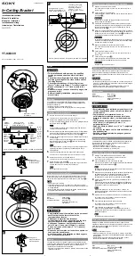
天井取り付け金具に延長パイプの上端

を固定する

延長用パイプに付属の M5 ねじ 4 本で固定

します。

● 図のようにパイプの開放部は天井取り付け金具

の開放部に対して 180 度になる向きで取り付

けます。

7


連結金具を延長パイプの下端に取り付
ける

準備のときに天井取り付け金具から外して

おいた M5 ねじ 4 本で固定します。

8


本体取り付け金具を連結金具に掛けて
仮止めする

① 連結金具の突起 (A) に引っ掛け、付属の

M5 ねじ (B)4 本で仮止めします。 

ねじ(B)は「投写角度の調整」(P.11)

の後でしっかり締めて固定してください。

②  付属のキヤノンロゴシールを貼ります。

ロゴシールの向きと位置は、7 ページの

手順 8 を参照してください。

スクリーン方向

スクリーン方向

スクリーン方向

B

A

B

Содержание RS-CL07

Страница 1: ...de Montaje en Techo Deckenmontagehalterung Staffa di installazione per soffitto Plafondbevestiging 使用説明書 Installation Manual Manuel d installation Manual de Instalación Installationsanleitung Manuale d installazione Installatiehandleiding RS CL07 RS CL10 JPN ENG FRA SPA GER ITA NLD ...

Страница 2: ...上の注意についてはプロジェクターの使用説明書を参照してください 取り付け適合機種 RS CL07 WUX10 MarkII SX7 MarkII SX60 X700 RS CL10 SX80 MarkII SX800 本製品は プロジェクターを天井から吊り下げて使用するための設置器具です RS CL07 用 RS CL10 用 質量 RS CL07 3 7kg RS CL10 4 1kg 質量 RS CL08 2 2kg RS CL09 3 4kg 2009年12月現在 注意 作業工程の中で天井取り付け金具 と連結金具はいったん分離させる 必要があります RS CL09 外側 内側パイプ 外側 内側カバー M5 ねじ 12mm 4 本 M3 ねじ 10mm 1 本 延長量は 55 95cm で 5cm ごとに調整できます RS CL08 外側 内側パイプ 外側 内側カバー M5 ねじ 12...

Страница 3: ... 168 mm 62 mm 284 mm 62 mm 249 mm 41 mm 168 mm 346 mm 178 mm RS CL07 WUX10 MarkII 投写距離 高さ ℓ 側面図 正面図 上面図 高さ 幅 16 10 画面サイズ 対角 幅 画面サイズと投写距離 画面サイズ 型 幅 高さcm 40 86 54 60 129 81 80 172 108 100 215 135 150 323 202 180 388 342 200 431 269 250 538 337 300 646 404 投写距離 m ズーム最大時 1 2 1 8 2 4 3 0 4 5 5 4 6 1 7 6 9 1 投写距離 m ズーム最小時 1 8 2 6 3 5 4 4 6 7 8 0 8 9 プロジェクターのズーム機能で画面サイズを変更することにより 表中の範囲で距離を調整できます 天井からレンズ中...

Страница 4: ... 画面サイズ 対角 投写距離 H2 高さ H1 高さ ℓ 側面図 正面図 上面図 高さ 幅 幅 画面サイズと投写距離 画面サイズ 型 幅 高さcm 40 81 61 60 122 91 80 163 122 100 203 152 150 305 229 182 370 277 200 406 305 250 508 381 300 610 457 投写距離 m ズーム最大時 1 2 1 8 2 4 3 0 4 5 5 4 5 9 7 4 8 9 投写距離 m ズーム最小時 2 0 2 9 3 9 4 9 7 4 9 0 H1 cm 55 82 110 137 206 250 274 343 411 H2 cm 6 9 12 15 23 28 30 38 46 プロジェクターのズーム機能で画面サイズを変更することにより 表中の範囲で距離を調整できます ...

Страница 5: ...610 457 投写距離 m ズーム最大時 1 2 1 8 2 4 3 0 4 5 5 4 5 9 7 4 8 9 投写距離 m ズーム最小時 2 0 2 9 3 9 4 9 7 4 9 0 天井からレンズ中心までの距離 ℓ RS CL10 RS CL08を使用 RS CL09を使用 25 cm 60 cm 80 cm 80 cm 120 cm 100 mm 100 mm 80 mm 80 mm 100 mm 100 mm 80 mm 80 mm 178 mm 164 mm 59 mm 342 mm 178 mm 164 mm 332 mm 59 mm 45 mm 249 mm RS CL10 SX80 MarkII SX800 投写距離 高さ ℓ 側面図 正面図 上面図 天井取り付け金具 高さ 幅 4 3 画面サイズ 対角 幅 ...

Страница 6: ...の穴を開けます 穴の位置を決めるときは 付属のテンプレー ト紙をご使用ください テンプレート紙にはスクリーンの方向が記載 されています 2 天井取り付け金具を天井に固定する 金具の矢印をスクリーンに向け M13 ね じ 4 本で天井に固定します 金具の取り付け前にテンプレート紙ははがし てください M13 ねじは同梱していません 天井の構造に 適したねじをご用意ください 3 本体取り付け金具をプロジェクターに 固定する 付 属 の M4 ね じ RS CL07 6 本 RS CL10 5 本 をご使用ください WUX10 MarkII SX7 MarkII SX60 X700 SX80 MarkII SX800 スクリーン方向 スクリーン方向 ...

Страница 7: ...通し もう一方の端を右側の調 整脚 B に掛けます 同様に落下防止ワイヤー RS CL10 の 場合は短い方 を角穴 C に通し もう 一方の端を左側の調整脚 D に掛けます 左右の調整脚を締めて 落下防止ワイ ヤーを固定します 落下防止ワイヤーは必ず 2 本とも取り付け てください 5 天井の穴からケーブル類を出す 6 天井取り付け金具に連結金具を固定する 準備のときに外した M5 ねじ 4 本で固定し ます B D A C スクリーン方向 WUX10 MarkII SX7 MarkII SX60 X700 SX80 MarkII SX800 B D A C ...

Страница 8: ... A に引っ掛け 付属の M5 ねじ B 4 本で仮止めします 図のようにケーブル類を引き出してください ねじ B は 投写角度の調整 P 11 の後 でしっかり締めて固定してください 8 ケーブル類を接続する プロジェクターにケーブル類を接続します 右の図のようにキヤノンロゴシールを貼 ります 設置が終わったら 投写角度を調 整してください P 11 B A WUX10 MarkII SX7 MarkII SX60 X700 の場合は 後ろにもシールを貼ります B ...

Страница 9: ...9を使用します 取り付け穴の位置 天井からレンズ光軸までの距離 ℓ RS CL08 RS CL09 a 60 cm 80 cm b 65 cm 85 cm c 70 cm 90 cm d 75 cm 95 cm e 80 cm 100 cm f 105 cm g 110 cm h 115 cm i 120 cm パイプの延長量 f a b c e g d h ℓ i ℓ 延長用パイプを最長の長さで使用する場合は 連続した 2 穴で固定してください ℓ 4 1cm WUX10 MarkII SX7 MarkII SX60 X700 4 5cm SX80 MarkII SX800 1 天井取り付け金具と連結金具をいった ん分離する P 5 準備 2 天井に穴を開ける P 5 手順 1 3 天井取り付け金具を天井に固定する P 5 手順 2 4 本体取り付け金具をプロジェクターに 固定する P ...

Страница 10: ... の開放部に対して 180 度になる向きで取り付 けます 7 連結金具を延長パイプの下端に取り付 ける 準備のときに天井取り付け金具から外して おいた M5 ねじ 4 本で固定します 8 本体取り付け金具を連結金具に掛けて 仮止めする 連結金具の突起 A に引っ掛け 付属の M5 ねじ B 4 本で仮止めします ねじ B は 投写角度の調整 P 11 の後でしっかり締めて固定してください 付属のキヤノンロゴシールを貼ります ロゴシールの向きと位置は 7 ページの 手順 8 を参照してください スクリーン方向 スクリーン方向 スクリーン方向 B A B ...

Страница 11: ...10 9 ケーブル類をパイプ内に配線し カ バーを閉める 天井の穴からケーブル類を引き出します パイプの内側にケーブル類を収納します パイプのカバーを内側 外側の順で閉め 延長用パイプに付属の M3 ねじ 1 本で固 定します ケーブル類をプロジェクターに接続します 設置が終わったら 投写角度を調 整してください P 11 ...

Страница 12: ...しないように支えてください 水平方向の投写角度 ひずみ を調整する 蝶ねじ A 2 本をゆるめ 本体を左右に 動かして水平方向の投写角度を調整しま す 位置が決まったら 蝶ねじを締めて固定 します 垂直方向の投写角度 ひずみ を調整する ねじ B 4 本 蝶ねじ C 2 本の順に ゆるめ 本体を上下に動かして垂直方向 の投写角度を調整します 位置が決まったら 蝶ねじ C ねじ B の順に締めて固定します 画面の傾きを調整する ねじ D 4 本をゆるめ 本体の傾きを調 整します 位置が決まったら ねじ D を締めて固 定します 水平方向の投写角度を調整する 垂直方向の投写角度を調整する 画面の傾きを調整する 5 5 20 5 10 A B C D ...

Страница 13: ...プの交換およびエアフィルターの清掃 交換ができます プロジェクター本体を支えた状態で 蝶 ねじ A 2 本を外し 本体取り付け金 具をゆっくりと開きます ランプの交換 またはエアフィルターの 清掃 交換を行います ランプの交換 またはエアフィルターの 清掃 交換が終わったら プロジェクター 本体を持ち上げ 本体取り付け金具を閉 じて蝶ねじ A を締めて固定します RS CL10 の場合 フィルターカバー ランプカバー RS CL07 の場合 仕 様 ランプの交換およびエアフィルターの清掃 交換は プロジェクターの電源を切り 電源プラグを コンセントから抜き 本体が十分に冷えた状態で行ってください ランプの交換およびエアフィルターの清掃 交換の手順は プロジェクターの使用説明書を参照し てください ランプの交換後は 投射角度および画面の傾きを確認してください 調整方法は P 11を参照して ...

Страница 14: ...ot remodel any part For details on cautions on using the projector refer to the User s Manual that came with the projector Applicable projector models RS CL07 WUX10 MarkII SX7 MarkII SX60 X700 RS CL10 SX80 MarkII SX800 The Ceiling mount Hanger is used to secure the projector to the ceiling RS CL07 RS CL10 Weight RS CL07 3 7 kg 8 2 lbs RS CL10 4 1 kg 9 1 lbs Weight RS CL08 2 2 kg 4 9 lbs RS CL09 3 ...

Страница 15: ...he projector sideways distorts the projected image Caution 178 mm 168 mm 62 mm 284 mm 62 mm 249 mm 41 mm 168 mm 346 mm 178 mm l Projection Distance Side view Front view Height Top view Width Screen Size and Projection Distance Screen size inch Width x height cm 40 86 54 60 129 81 80 172 108 100 215 135 150 323 202 180 388 342 200 431 269 250 538 337 300 646 404 Projection distance Zoom max 1 2 m 3...

Страница 16: ...60 cm 2 0 to 80 cm 2 6 80 cm 2 6 to 120 cm 3 9 Screen size inch Width x height cm 40 81 61 60 122 91 80 163 122 100 203 152 150 305 229 182 370 277 200 406 305 250 508 381 300 610 457 Projection distance Zoom max 1 2 m 3 9 1 8 m 5 9 2 4 m 7 9 3 0 m 9 8 4 5 m 14 8 5 4 m 17 7 5 9 m 19 4 7 4 m 24 2 8 9 m 29 2 Projection distance Zoom min 2 0 m 6 6 2 9 m 9 6 3 9 m 12 9 4 9 m 16 1 7 4 m 24 2 9 0 m 29 5...

Страница 17: ...6 m 24 9 9 1 m 29 9 Projection distance Zoom min 1 7 m 5 6 2 6 m 8 5 3 5 m 11 5 4 4 m 14 4 76 6 m 21 7 8 0 m 26 3 8 9 m 29 2 The distance can be adjusted within the range shown above by changing the screen size using the zoom function of the projector Distance from ceiling to lens center l RS CL07 RS CL10 When RS CL08 is used When RS CL09 is used 25 cm 0 8 60 cm 2 0 to 80 cm 2 6 80 cm 2 6 to 120 c...

Страница 18: ...ion to the screen is indicated on the template sheet 2Secure the Ceiling mount bracket to the ceiling Use four M13 screws to secure the Ceiling mount bracket to the ceiling with the arrow facing toward the screen Before securing the Ceiling mount bracket be sure to remove the template sheet The M13 screws are not included in the supplied parts Prepare the M13 screws suitable for the ceiling struct...

Страница 19: ...er wire for RS CL10 into the square hole C and then fasten the other end to the left adjusting foot D 4 Tighten the left and right adjusting feet to secure the anti fall wires Be sure to attach both anti fall wires 5 Pull cables out of the cable hole in the ceiling 6 Attach the Joint fitting to the Ceiling mount bracket Secure the Ceiling mount bracket using the four M5 screws removed during prepa...

Страница 20: ...s B Pull out the cables as shown Be sure to secure screws B tightly after making the adjustment discussed in Adjusting the Projection Angle page 11 8 Connect cables 1 Connect cables to the projector 2 Affix the supplied Canon logo seal as shown After completion of installation adjust the projection angle page 11 A B For WUX10 MarkII SX7 MarkII SX60 X700 affix an additional seal at the back B ...

Страница 21: ...ews and leave an unused screw hole between them When the extension pipe is stretched to its maximum length insert the screws in two adjacent screw holes Installation to a High Ceiling Use optional extension pipe RS CL08 or RS CL09 for high ceiling 1 2 Pipe extension length f a b c e g d h l To use the extension pipe with it extended to the maximum length secure it by inserting screws in the two ad...

Страница 22: ...unt bracket during preparation 8 Hook the Base bracket on the projections of the Joint fitting and secure it temporarily 1 Hook the Base bracket on the protrusion A of the Joint fitting and secure it temporarily using the four supplied M5 screws B Tighten the screws B after making the adjustment in Adjusting the Projection Angle page 11 2 Affix the supplied Canon logo seal For the direction and po...

Страница 23: ... hole in the ceiling 2 Put the cables inside the pipe 3 Close the inner cover of the pipe and then close outer cover of the pipe Secure to the extension pipe using the supplied M3 screw 4 Connect the cables to the projector After completion of installation adjust the projection angle page 11 ...

Страница 24: ...rojection angle 2 When the projector is correctly positioned tighten the wing screw Adjust the vertical projection angle 1 First loosen four screws B and then loosen two wing screws C Move the projector vertically to adjust the vertical projection angle 2 When the projector is correctly positioned first tighten the wing screws C and next tighten the four screws B Adjust the screen inclination 1 Lo...

Страница 25: ...d 5 leftward or rightward Vertical projection angle 5 upward or 20 downward 5 upward or 20 downward Screen slant angle 5 5 Outer dimension of assembly excluding projection 222 7 mm W x 281 5 mm D x 175 8 mm H 0 7 W x 0 9 D x 0 6 H 310 5 mm W x 276 2 mm D x 178 2 mm H 1 0 W x 0 9 D x 0 6 H Weight Ceiling mount Hanger only 3 7 kg 8 2 lbs 4 1 kg 9 1 lbs Specifications Before replacing the lamp or cle...

Страница 26: ...ent le dispositif de suspension au plafond en conformité avec ce manuel Veillez à serrer les vis fermement Ne remodelez aucune pièce Pour des détails ou des mesures de précaution concernant l utilisation du projecteur reportez vous au manuel d utilisation accompagnant le projecteur Modèles de projecteur concernés RS CL07 WUX10 MarkII SX7 MarkII SX60 X700 RS CL10 SX80 MarkII SX800 Le dispositif de ...

Страница 27: ... ci dessous Installez le projecteur tout droit en face de l écran Un montage en biais du projecteur déformera l image projetée Attention 178 mm 168 mm 62 mm 284 mm 62 mm 249 mm 41 mm 168 mm 346 mm 178 mm Vue de face Vue de côté Dimensions de l écran et distance de projection Dimensions de l écran pouces largeur x hauteur en cm 40 86 54 60 129 81 80 172 108 100 215 135 150 323 202 180 388 342 200 4...

Страница 28: ...ouces largeur x hauteur en cm 40 81 61 60 122 91 80 163 122 100 203 152 150 305 229 182 370 277 200 406 305 250 508 381 300 610 457 Distance de projection zoom maxi 1 2 m 1 8 m 2 4 m 3 0 m 4 5 m 5 4 m 5 9 m 7 4 m 8 9 m Distance de projection zoom mini 2 0 m 2 9 m 3 9 m 4 9 m 7 4 m 9 0 m H1 55 cm 82 cm 110 cm 137 cm 206 cm 250 cm 274 cm 343 cm 411 cm H2 6 cm 9 cm 12 cm 15 cm 23 cm 28 cm 30 cm 38 cm...

Страница 29: ...hauteur en cm 40 81 61 60 122 91 80 163 122 100 203 152 150 305 229 182 370 277 200 406 305 250 508 381 300 610 457 Distance de projection zoom maxi 1 2 m 1 8 m 2 4 m 3 0 m 4 5 m 5 4 m 5 9 m 7 4 m 8 9 m Distance de projection zoom mini 2 0 m 2 9 m 3 9 m 4 9 m 7 4 m 9 0 m Dimensions de l écran et distance de projection Distance entre le plafond et le centre de lentille l RS CL07 RS CL10 Lorsque RS ...

Страница 30: ... la feuille gabarit prévue en accessoire La direction de l écran est indiquée sur la feuille gabarit 2Fixez la monture au plafond Utilisez quatre vis M13 pour fixer la monture au plafond en orientant la flèche vers l écran Avant de fixer la monture n oubliez pas d enlever la feuille gabarit Les vis M13 ne sont pas fournies Préparez donc des vis M13 appropriées à la structure du plafond 3 Attachez ...

Страница 31: ... antichute fil court pour pour RS CL10 dans le trou carré C puis fixez l autre extrémité à la vis de réglage gauche D 4 Serrez les vis de réglage gauche et droite pour fixer les fils antichutes Attachez sûrement les deux fils antichutes 5 Retirez les câbles par le trou de câble dans le plafond 6 Attachez la ferrure d assemblage à la monture Fixez la monture en utilisant les quatre vis M5 enlevées ...

Страница 32: ...e dessin Serrez fermement les vis B après avoir effectué l ajustement décrit au paragraphe Ajustement de l angle de projection page 11 8 Connectez les câbles 1 Raccordez les câbles au projecteur 2 Appliquez l étiquette de logo Canon autocollante comme l indique le dessin A la fin de l installation ajustez l angle de projection page 11 Pour WUX10 MarkII SX7 MarkII SX60 X700 appliquez une étiquette ...

Страница 33: ...fond haut Utilisez le tuyau d extension RS CL08 ou RS CL09 pour un plafond élevé 1 2 Position de trou de montage Distance l entre plafond et axe de lentille RS CL08 RS CL09 a 60 cm 80 cm b 65 cm 85 cm c 70 cm 90 cm d 75 cm 95 cm e 80 cm 100 cm f 105 cm g 110 cm h 115 cm i 120 cm Longueur de tuyau d extension f a b c e g d h l Pour utiliser le tuyau d extension à l état allongé à sa longueur maximu...

Страница 34: ...paration 8 Accrochez le support de base aux bossages de la ferrure d assemblage et fixez le provisoirement 1 Accrochez le support de base au bossage A de la ferrure d assemblage et fixez le provisoirement avec les quatre vis M5 four nies B Serrez les vis B après avoir effectué l ajus tement décrit au paragraphe Ajustement de l angle de projection page 11 2 Appliquez l étiquette de logo Canon auto ...

Страница 35: ...e dans le plafond 2 Posez les câbles dans le tuyau 3 Remettez en place le couvercle intérieur de tuyau puis le couvercle de tuyau ex térieur Fixez les au tuyau d extension en utilisant la vis M3 fournie 4 Connectez les câbles au projecteur A la fin de l installation ajustez l an gle de projection page 11 ...

Страница 36: ...izontal 2 Lorsque le projecteur est positionné correctement serrez les vis à oreilles Ajustement de l angle de projection vertical 1 Desserrez premièrement quatre vis B puis deux vis à oreilles C Déplacez le projecteur verticalement pour ajuster l angle de projection vertical 2 Lorsque le projecteur est positionné correctement serrez premièrement les vis à oreilles C et ensuite les quatre vis B Aj...

Страница 37: ...gle de projection vertical 5 en haut ou 20 en bas 5 en haut ou 20 en bas Angle d inclinaison de l écran 5 5 Encombrement de l ensemble à l exclusion du bossage 222 7mm larg x281 5mm prof x175 8mm haut 310 5mm larg x276 2mm prof x178 2mm haut Poids dispositif de suspension au plafond seulement 3 7 kg 4 1 kg Spécifications Avant de remplacer la lampe ou de nettoyer remplacer le filtre à air n oublie...

Страница 38: ...e Soporte Colgante de Montaje en Techo de acuerdo con este manual Asegúrese de apretar bien los tornillos No remodele ninguna pieza Si desea más información en lo referente a precauciones que se han de tomar al utilizar el pro yector consulte el Manual del Usuario suministrado con el proyector Modelos de proyector aplicables RS CL07 WUX10 MarkII SX7 MarkII SX60 X700 RS CL10 SX80 MarkII SX800 El So...

Страница 39: ...se indica a continuación Instale el proyector recto en frente de la pantalla El montaje del proyector en ángulo distorsiona la imagen proyectada Precauciones 178 mm 168 mm 62 mm 284 mm 62 mm 249 mm 41 mm 168 mm 346 mm 178 mm l Altura Distancia de proyección Soporte para montaje en techo Vista lateral Vista de frente Ancho Ancho Altura 16 10 Tamaño de la pantalla Distancia desde el techo hasta el c...

Страница 40: ...royección Tamaño de la pantalla pulg Ancho x altura cm 40 81 61 60 122 91 80 163 122 100 203 152 150 305 229 182 370 277 200 406 305 250 508 381 300 610 457 Distancia de proyección Zoom máx 1 2 m 1 8 m 2 4 m 3 0 m 4 5 m 5 4 m 5 9 m 7 4 m 8 9 m Distancia de proyección Zoom mín 2 0 m 2 9 m 3 9 m 4 9 m 7 4 m 9 0 m H1 55 cm 82 cm 110 cm 137 cm 206 cm 250 cm 274 cm 343 cm 411 cm H2 6 cm 9 cm 12 cm 15 c...

Страница 41: ...Distancia de Proyección Tamaño de la pantalla pulg Ancho x altura cm 40 81 61 60 122 91 80 163 122 100 203 152 150 305 229 182 370 277 200 406 305 250 508 381 300 610 457 Distancia de proyección Zoom máx 1 2 m 1 8 m 2 4 m 3 0 m 4 5 m 5 4 m 5 9 m 7 4 m 8 9 m Distancia de proyección Zoom mín 2 0 m 2 9 m 3 9 m 4 9 m 7 4 m 9 0 m Distancia desde el techo hasta el centro de la lente l RS CL07 RS CL10 Cu...

Страница 42: ...acia la pantalla está indicada en la hoja modelo 2Asegure en el techo el Soporte para montaje en techo Use cuatro tornillos M13 a fin de asegurar en el techo el Soporte para montaje en techo con la flecha orientada hacia la pantalla Antes de asegurar el Soporte para montaje en techo cerciórese de retirar la hoja modelo Los tornillos M13 no se incluyen entre las partes suministradas Prepare los tor...

Страница 43: ...CL10 a través del orificio rectangular C y luego fije el otro extremo al pie ajustable izquierdo D 4 Apriete los pies ajustables izquierdo y derecho para asegurar los cables contra caídas Asegúrese de acoplar ambos cables contra caídas 5 Tire y saque los cables por el orificio para cables del techo 6 Acople el Accesorio de unión al Soporte para montaje en techo Asegure el Soporte para montaje en t...

Страница 44: ...es tal como se indica Cerciórese de asegurar firmemente los tornillos B después de hacer el ajuste que se explica en Ajuste del Ángulo de Proyección página 11 8 Conecte los cables 1 Conecte los cables al proyector 2 Pegue el sello con el logo Canon sumi nistrado tal como se indica Después de completada la instalación ajuste el ángulo de proyección página 11 A B Para el WUX10 MarkII SX7 MarkII SX60...

Страница 45: ...e el tubo de extensión opcional RS CL08 o RS CL09 1 2 Posición del orificio de montaje Distancia desde el techo hasta el eje de la lente l RS CL08 RS CL09 a 60 cm 80 cm b 65 cm 85 cm c 70 cm 90 cm d 75 cm 95 cm e 80 cm 100 cm f 105 cm g 110 cm h 115 cm i 120 cm Longitud de extensión del tubo f a b c e g d h l Para usar el tubo de extensión en la condición de extendido hasta su máxima longitud aseg...

Страница 46: ...urante los preparativos 8 Enganche el Soporte de base en las salientes del Accesorio de unión y asegúrelo temporalmente 1 Enganche el Soporte de base en la pro tuberancia A del Accesorio de unión y asegúrelo temporalmente usando los cuatro tornillos M5 suministrados B Apriete los tornillos B después de hacer el ajuste indicado en Ajuste del Ángulo de Proyección página 11 2 Pegue el sello con el lo...

Страница 47: ...el techo 2 Ponga los cables en el interior del tubo 3 Cierre la cubierta interior del tubo y lue go cierre la cubierta exterior del tubo Asegure el tubo de extensión usando los tornillos M3 suministrados 4 Conecte los cables al proyector Después de completada la instalación ajuste el ángulo de proyección página 11 ...

Страница 48: ...Cuando el proyector esté correctamente posicionado apriete los tornillos de orejetas Ajuste del ángulo de proyección vertical 1 Primero afloje los cuatro tornillos B y luego afloje los dos tornillos de orejetas C Mueva el proyector verticalmente para ajustar el ángulo de proyección vertical 2 Cuando el proyector esté correctamente posicionado primero apriete los tornillos de orejetas C y a continu...

Страница 49: ...a o derecha Ángulo de proyección vertical 5 hacia arriba o 20 hacia abajo 5 hacia arriba o 20 hacia abajo Angle d inclinaison de l écran 5 5 Ángulo de inclinación de la pantalla excluyendo la proyección 222 7 mm An x 281 5 mm Prof x 175 8 mm Al 310 5 mm An x 276 2 mm Prof x 178 2 mm Al Peso sólo el Soporte Colgante de Montaje en Techo 3 7 kg 4 1 kg Especificaciones Antes de la sustitución de la lá...

Страница 50: ...g genau an diese Anleitung Achten Sie darauf die Schrauben sicher anzuziehen Nehmen Sie keinen Umbau an Teilen vor Einzelheiten zu Sicherheitsmaßnahmen bei der Bedienung des Projektors finden Sie in der Bedie nungsanleitung des Projektors Für Projektor Modelle RS CL07 WUX10 MarkII SX7 MarkII SX60 X700 RS CL10 SX80 MarkII SX800 Die Deckenmontagehalterung ermöglicht die hängende Installation des Pro...

Страница 51: ...abstand ist unten dargestellt Installieren Sie den Projektor in einer geraden Linie vor dem Bildschirm Bei seitlicher Installation des Projektors wird das projizierte Bild verzerrt Vorsicht 178 mm 168 mm 62 mm 284 mm 62 mm 249 mm 41 mm 168 mm 346 mm 178 mm l Höhe Projektionsabstand Breite Seitenansicht Frontansicht Deckenmontagehalterung Höhe Breite 16 10 Projektionsbildg röße Abstand Decke Objekt...

Страница 52: ...verstellt werden indem die Bildschirmgröße mit Hilfe der Zoomfunktion des Projektors verändert wird Bildschirmgröße und Projektionsabstand Bildschirmgröße Zoll Breite x Höhe cm 40 81 61 60 122 91 80 163 122 100 203 152 150 305 229 182 370 277 200 406 305 250 508 381 300 610 457 Projektionsabstand max Zoom 1 2 m 1 8 m 2 4 m 3 0 m 4 5 m 5 4 m 5 9 m 7 4 m 8 9 m Projektionsabstand min Zoom 2 0 m 2 9 m...

Страница 53: ...gezeigten Bereich verstellt werden indem die Bildschirmgröße mit Hilfe der Zoomfunktion des Projektors verändert wird Bildschirmgröße und Projektionsabstand Bildschirmgröße Zoll Breite x Höhe cm 40 81 61 60 122 91 80 163 122 100 203 152 150 305 229 182 370 277 200 406 305 250 508 381 300 610 457 Projektionsabstand max Zoom 1 2 m 1 8 m 2 4 m 3 0 m 4 5 m 5 4 m 5 9 m 7 4 m 8 9 m Projektionsabstand mi...

Страница 54: ...ldschirm weisende Richtung ist auf der Schablone angegeben 2Die Deckenmontagehalterung an der Decke befestigen Befestigen Sie die Deckenmontagehalterung mit vier Schrauben M13 so an der Decke dass der Pfeil in Richtung Bildschirm zeigt Vergessen Sie nicht die Schablone zu entfernen bevor Sie die Deckenmontagehalterung befestigen Die Schrauben M13 sind nicht im Lieferumfang enthalten Bitte beschaff...

Страница 55: ...e für RS CL10 durch die viereckige Öffnung C und befestigen Sie das andere Ende am linken Verstellfuß D 4 Ziehen Sie die Verstellfüße wieder fest um die Fangleinen zu sichern Bringen Sie unbedingt beide Fangleinen an 5 Die Kabel durch die Kabeldurchführung aus der Decke herausführen 6 Das Verbindungsblech an der Deckenmontagehalterung befestigen Befestigen Sie die Deckenmontagehalterung mit den vo...

Страница 56: ...wissern Sie sich das die Schrauben B nach dem unter Einstellung des Projektionswinkels Seite 11 beschriebenen Verfahren wieder gut festgezogen wurden 8 Kabel anschließen 1 Die Kabel an den Projektor anschließen 2 Bringen Sie den Aufkleber mit dem Canon Logo gemäß Abbildung an Stellen Sie anschließend an die Installation den Projektionswinkel ein Seite 11 A B Bei den Modellen WUX10 MarkII SX7 MarkI...

Страница 57: ...as optionale Verlängerungsrohr RS CL08 oder RS CL09 für eine hohe Decke 1 2 Schraubenloch Abstand von der Decke zur Objektivachse I RS CL08 RS CL09 a 60 cm 80 cm b 65 cm 85 cm c 70 cm 90 cm d 75 cm 95 cm e 80 cm 100 cm f 105 cm g 110 cm h 115 cm i 120 cm Rohrlänge f a b c e g d h l Wenn Sie das Verlängerungsrohr auf volle Länge ausziehen befestigen Sie es indem Sie die Schrauben in zwei benachbart...

Страница 58: ...kenmontagehalterung entfernten Schrau ben M5 B 8 Die Grundplatte auf die Zapfen des Verbindungsblechs haken und provisorisch befestigen 1 Hängen Sie die Grundplatte auf die Zapfen A des Verbindungsblechs und sichern Sie sie provisorisch mit den vier mitgelieferten Schrauben M5 B Ziehen Sie die Schrauben B nach dem unter Einstellung des Projektionswin kels Seite 11 beschriebenen Verfahren wieder gu...

Страница 59: ...el durch die Kabeldur chführung aus der Decke heraus 2 Legen Sie die Kabel in das Rohr 3 Sichern Sie das Verlängerungsrohr mit den mitgelieferten Schrauben M3 4 Schließen Sie die Kabel an den Projektor an Stellen Sie anschließend an die Installation den Projektionswinkel ein Seite 11 ...

Страница 60: ...or in der richtigen Stellung befindet drehen Sie die Flügelschrauben fest Den vertikalen Projektionswinkel einstellen 1 Lösen Sie zunächst die vier Schrauben B dann die zwei Flügelschrauben C Gleichen Sie den vertikalen Projektionswinkel ab indem Sie die Höhe des Projektors verändern 2 Wenn sich der Projektor in der richtigen Stellung befindet drehen Sie zunächst die Flügelschrauben C fest und dan...

Страница 61: ...izontaler Projektionswinkel jeweils 5 nach rechts und links jeweils 5 nach rechts und links Vertikaler Projektionswinkel 5 nach oben oder 20 nach unten 5 nach oben oder 20 nach unten Neigungswinkel des Bildschirms 5 5 Außenabmessungen montiert ohne Überstände 222 7 mm B x 281 5 mm T x 175 8 mm H 310 5 mm B x 276 2 mm T x 178 2 mm H Gewicht nur Deckenmontagehalterung 3 7 kg 4 1 kg Technische Daten ...

Страница 62: ...ta staffa di installazione per soffitto seguendo le indicazioni di questo manuale Assicurarsi di fissare le viti in modo sicuro Non rimodellare nessuna parte Per ulteriori dettagli sulle precauzioni da adottare durante l utilizzo del proiettore consultare il Manuale dell utente in dotazione Modèles de projecteur concernés RS CL07 WUX10 MarkII SX7 MarkII SX60 X700 RS CL10 SX80 MarkII SX800 La staff...

Страница 63: ...illustrato di seguito Installare il proiettore esattamente davanti allo schermo L installazione del proiettore con una angolazione produce una distorsione dell immagine Attenzione 178 mm 168 mm 62 mm 284 mm 62 mm 249 mm 41 mm 168 mm 346 mm 178 mm l Altezza Distanza di proiezione Larghezza Visione laterale Visione anteriore Staffa di installazione per soffitto Larghezza Altezza 16 10 Dimensioni sch...

Страница 64: ...ro la gamma vista cambiando le dimensioni dell immagine con la funzione di zoom del proiettore Dimensioni dello schermo e distanza di proiezione Dimensioni dello schermo in pollici larghezza x altezza in cm 40 81 61 60 122 91 80 163 122 100 203 152 150 305 229 182 370 277 200 406 305 250 508 381 300 610 457 Distanza di proiezione zoom massimo 1 2 m 1 8 m 2 4 m 3 0 m 4 5 m 5 4 m 5 9 m 7 4 m 8 9 m D...

Страница 65: ...golata entro la gamma vista cambiando le dimensioni dell immagine con la funzione di zoom del proiettore Dimensioni dello schermo e distanza di proiezione Dimensioni dello schermo in pollici larghezza x altezza in cm 40 81 61 60 122 91 80 163 122 100 203 152 150 305 229 182 370 277 200 406 305 250 508 381 300 610 457 Distanza di proiezione zoom massimo 1 2 m 1 8 m 2 4 m 3 0 m 4 5 m 5 4 m 5 9 m 7 4...

Страница 66: ... dotazione La direzione dello schermo è indicata sulla mascherina 2Fermare la staffa di installazione per soffitto al soffitto sare quattro viti M13 per fermare la staffa di installazione per soffitto al soffitto con la freccia orientata verso lo schermo Prima di fermare la staffa di installazione per soffitto non dimenticare di togliere la mascherina Le viti M13 non sono accluse al corredo Procur...

Страница 67: ...o dell RS CL10 nel foro quadrato C della staffa di base e quindi fissare l altra estremità al piedino regolabile sinistro D 4 Stringere i piedini regolabili sinistro e destro per fissare i fili di sicurezza Applicare sempre ambedue i fili di sicurezza 5 Tirare i cavi fuori dal foro apposito aperto nel soffitto 6 Applicare il giunto alla staffa di installazione per soffitto Fermare la staffa di ins...

Страница 68: ... visto in figura Dopo aver terminate le operazioni descritte in Regolazione dell angolo di proiezione pagina 11 non dimenticare di stringere bene le viti B 8 Collegare i cavi 1 Collegare i cavi al proiettore 2 Fissare l adesivo col logo Canon nel modo visto in figura Terminata l installazione regolare l angolo di proiezione pagina 11 A B Nel caso degli WUX10 MarkII SX7 MarkII SX60 X700 applicare a...

Страница 69: ...u soffitti alti usare il tubo opzionale di estensione RS CL08 o RS CL09 1 2 Posizione del foro di installazione Distanza dal soffitto all asse l della lente RS CL08 RS CL09 a 60 cm 80 cm b 65 cm 85 cm c 70 cm 90 cm d 75 cm 95 cm e 80 cm 100 cm f 105 cm g 110 cm h 115 cm i 120 cm Lunghezza del tubo di estensione f a b c e g d h l Per usare il tubo di estensione del tutto esteso fermarlo inserendo l...

Страница 70: ...ante la preparazione della staffa di instal lazione per soffitto 8 Agganciare la staffa di base della proiezione del giunto e fermarla temporaneamente 1 Agganciare la staffa di base alla protrusione A del giunto e fermarla temporaneamente con le quattro viti M5 in dotazione B Stringere le viti B dopo aver fatto le re golazioni viste in Regolazione dell ango lo di proiezione pagina 11 2 Applicare l...

Страница 71: ...itto 2 Far passare i cavi attraverso il tubo 3 Chiudere il rivestimento interno del tubo e quindi il suo rivestimento esterno Fermare il tubo di estensione usando la vite M3 in dotazione 4 Collegare i cavi al proiettore Completata l installazione passare alla regolazione dell angolo di proie zione pagina 11 ...

Страница 72: ...golo di proiezione orizzontale 2 Una volta che il proiettore è nella posizione desiderata stringere i dadi a farfalla Regolare l angolo di proiezione verticalel 1 Prima allentare le quattro viti B e poi i due dadi a farfalla C Muovere il proiettore verticalmente per regolare l angolo di proiezione verticale 2 Una volta che il proiettore è nella posizione desiderata stringere prima i dadi a farfall...

Страница 73: ...e 5 a destra o sinistra 5 a destra o sinistra Angolo di proiezione verticale 5 in su o 20 in giù 5 in su o 20 in giù Angolazione dell immagine 5 5 Dimensioni esterne dell apparecchio Staffa di sospensione dal soffitto 222 7 mm L x 281 5 mm P x 175 8 mm A 310 5 mm L x 276 2 mm P x 178 2 A Peso solo staffa di installazione per soffitto 3 7 kg 4 1 kg Caratteristiche tecniche Prima di sostituire la la...

Страница 74: ...stemming met deze handleiding Draai de schroeven stevig vast Voer geen wijzigingen uit aan de onderdelen Voor meer informatie over de veiligheidsvoorschriften waar u zich tijdens het gebruik van de projector aan moet houden raadpleegt u de gebruikershandleiding van de projector Geschikt voor de projectormodellen RS CL07 WUX10 MarkII SX7 MarkII SX60 X700 RS CL10 SX80 MarkII SX800 De plafondbevestig...

Страница 75: ...ngegeven Installeer de projector recht voor het scherm Als de projector schuin geïnstalleerd wordt zal het geprojecteerde beeld vervormd worden Pas op 178 mm 168 mm 62 mm 284 mm 62 mm 249 mm 41 mm 168 mm 346 mm 178 mm Projectie afstand l Hoogte Breedte Zijaanzicht Vooraanzicht Plafondbevestigingsplaat Breedte Hoogte 16 10 Schermformaat Afstand van het plafond tot het midden van de lens l RS CL07 R...

Страница 76: ...20 cm De afstand kan worden ingesteld binnen het hierboven vermelde bereik door de schermafmetingen te veranderen met behulp van de zoomfunctie van de projector Schermafmetingen inch breedte x hoogte cm 40 81 61 60 122 91 80 163 122 100 203 152 150 305 229 182 370 277 200 406 305 250 508 381 300 610 457 Projectie afstand Zoom max 1 2 m 1 8 m 2 4 m 3 0 m 4 5 m 5 4 m 5 9 m 7 4 m 8 9 m Projectie afst...

Страница 77: ... en projectie afstand De afstand kan worden ingesteld binnen het hierboven vermelde bereik door de schermafmetingen te veranderen met behulp van de zoomfunctie van de projector Schermafmetingen inch breedte x hoogte cm 40 81 61 60 122 91 80 163 122 100 203 152 150 305 229 182 370 277 200 406 305 250 508 381 300 610 457 Projectie afstand Zoom max 1 2 m 1 8 m 2 4 m 3 0 m 4 5 m 5 4 m 5 9 m 7 4 m 8 9 ...

Страница 78: ...aat aangegeven op het sjabloon 2Bevestig de plafondbevestigingsplaat aan het plafond Gebruik vier M13 schroeven om de pla fondbevestigingsplaat aan het plafond te bevestigen met de pijl in de richting van het scherm Vergeet niet het sjabloon weg te halen voor u de plafondbevestigingsplaat vast zet De M13 schroeven worden niet meegeleverd met de plafondbevestiging Zorg zelf voor M13 schroeven die g...

Страница 79: ...door het vierkante gat C en maak het andere uiteinde vast aan het linker instel voetje D 4 Draai de linker en rechter instelvoetjes vast om de veiligheidsdraden vast te zet ten U moet allebei de veiligheidsdraden vastma ken 5 Trek de bedrading door het gat in het plafond 6 Bevestig de verbindingskoppeling aan de plafondbevestigingsplaat Zet de verbindingskoppeling vast aan de plafondbevestigingspl...

Страница 80: ...t de schroeven B pas definitief vastdraaien nadat de instelling besproken onder Instellen van de projectiehoek bladzijde 11 is verricht 8 Sluit de bedrading aan 1 Sluit de bedrading aan op de projector 2 Plak de meegeleverde Canon sticker op de projector zoals staat aangegeven Wanneer de installatie tot dit punt ge vorderd is moet de projectiehoek wor den ingesteld bladzijde 11 A B Op de WUX10 Mar...

Страница 81: ...nd Gebruik de los verkrijgbare verlengpijp RS CL08 of RS CL09 voor een hoog plafond 1 2 Positie bevestigingsgat Afstand van het plafond tot de as van de lens l RS CL08 RS CL09 a 60 cm 80 cm b 65 cm 85 cm c 70 cm 90 cm d 75 cm 95 cm e 80 cm 100 cm f 105 cm g 110 cm h 115 cm i 120 cm Lengte verlengpijp f a b c e g d h l Om een verlengpijp op de maximale lengte te gebruiken dient u deze vast te zette...

Страница 82: ...n van de plafondbe vestigingsplaat verwijderd heeft 8 Haak de basisplaat aan de uitsteeksels van de verbindingskoppeling en zet dit provisorisch vast 1 Haak de basisplaat aan de uitsteeksels A van de verbindingskoppeling en zet dit provisorisch vast met de vier meegele verde M5 schroeven B Draai de schroeven B pas definitief vast nadat de instelling besproken onder In stellen van de projectiehoek ...

Страница 83: ...PLeid de bedrading door de pijp 3 Doe eerst de afdekking op de binnenpijp en vervolgens op de buitenpijp Zet de afdekkingen vast aan de verlengpijp met de meegeleverde M3 schroef 4 Sluit de bedrading aan op de projector Wanneer de installatie tot dit punt gevorderd is moet de projectiehoek worden ingesteld bladzijde 11 ...

Страница 84: ...tale projectiehoek in te stellen 2 Draai de vleugelschroeven weer vast wan neer de projector goed staat Stel de verticale projectiehoek in 1 Draai eerst de vier schroeven B los en vervolgens de twee vleugelschroeven C Beweeg de projector verticaal om de verti cale projectiehoek in te stellen 2 Wanneer de projector goed staat draait u eerst de vleugelschroeven C aan en dan de vier schroeven B Stel ...

Страница 85: ... naar links of rechts Verticale projectiehoek 5 naar boven of 20 naar beneden 5 naar boven of 20 naar beneden Schermhoekaanpassing 5 5 Buitenafmetingen gemonteerd exclusief uitsteeksels 222 7 mm b x 281 5 mm d x 175 8 mm h 310 5 mm b x 276 2 mm d x 178 2 mm h PGewicht alleen de plafondbevestiging 3 7 kg 4 1 kg Technische gegevens Voor de lamp vervangen of het luchtfilter gereinigd vervangen wordt ...

Страница 86: ...YT1 7354 002 CANON INC 2008 PRINTED IN JAPAN ...

Отзывы: