


Chapter 4
4-3
4.3
Adjustment
4.3.1
Adjustment at Time of Parts
Replacement
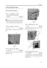
4.3.1.1
Adjusting the Punch
Hole Position (feed direction)
0003-4709
This adjustment is possible only with the host
machine service mode.
4.3.1.2
Sensor Output
Adjustment
0003-4710
Perform this adjustment when replacing the punch
controller PCB, transmittance sensor (photosensor
PCB/LED PCB), or deflection sensor (scrap full
detector PCB unit).
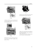
1) Check that the power of the host machine is off and
then remove the rear cover of the puncher.
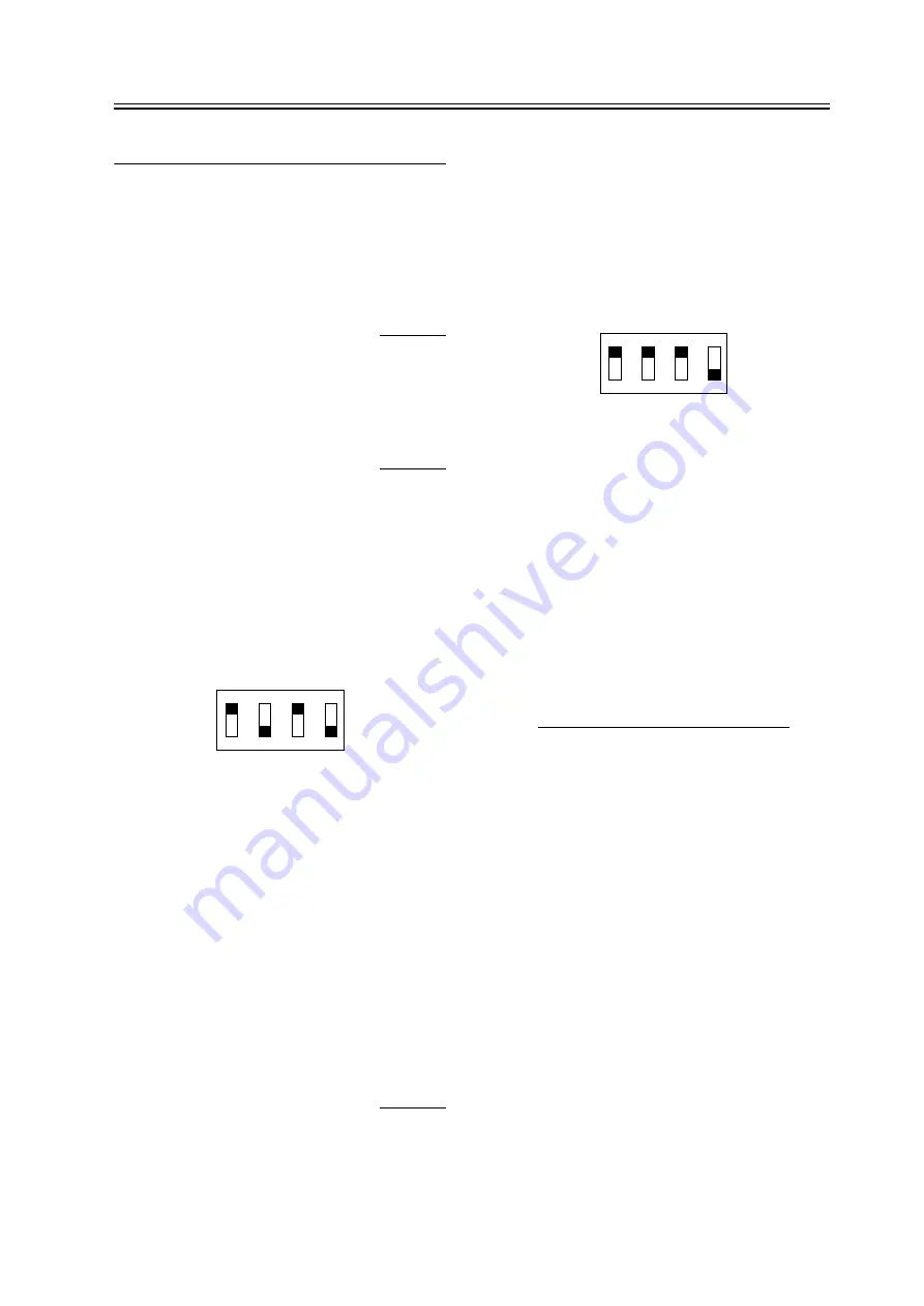
2) Set SW601 on the punch controller PCB as shown
below.
F-4-1
3) Turn on the power of the host machine.
4) Press SW602 on the punch controller PCB. Sensor
output is adjusted automatically when the switch is
pressed.
Adjustment is complete if LED601 and 602 on the
punch controller PCB flashes alternately.
5) Press SW602 or 603 on the punch controller PCB
to end the adjustment mode and set all bits of SW601
to OFF.
6) Turn off the power of the host machine.
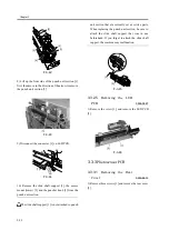
4.3.1.3
Registering the Number
of Punch Holes
0003-4711
This operation registers which puncher unit is
attached to the IC on the punch driver PCB so that the
puncher unit can be identified by the finisher. For this
reason, this operation must be performed when the
punch driver PCB has been replaced.
1) Check that the power of the host machine is off and
then remove the rear cover of the puncher.
2) Set SW601 on the punch controller PCB as shown
below.
F-4-2
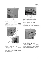
3) Turn on the power of the host machine.
4) Press SW602 on the punch controller PCB to select
the number of punch holes.
The items in the following table are displayed
repeatedly from top to bottom each time SW602 is
pressed.
T-4-3
ON
1
2
3
4
Number
of punch
holes
LED601/602
2
hole(Punc
her Unit-
L1)
Flash 1 times per cycle
2/3
hole(Punc
her Unit-
M1)
Flash 2 times per cycle
4
hole(Punc
her Unit-
N1(FRA))
Flash 3 times per cycle
4
hole(Punc
her Unit-
P1(SWD))
Flash 4 times per cycle
ON
1
2
3
4
Содержание Puncher Unit-L1
Страница 1: ...Feb 21 2005 Service Manual Finisher Sorter DeliveryTray Puncher Unit P1 ...
Страница 2: ......
Страница 6: ......
Страница 10: ......
Страница 11: ...Chapter 1 Specifications ...
Страница 12: ......
Страница 14: ......
Страница 19: ...Chapter 2 Functions ...
Страница 20: ......
Страница 22: ......
Страница 34: ......
Страница 35: ...Chapter 3 Parts Replacement Procedure ...
Страница 36: ......
Страница 53: ...Chapter 4 Maintenance ...
Страница 54: ......
Страница 56: ......
Страница 76: ...4 Mount the rear cover to the Puncher 5 Turn on the power of the host machine ...
Страница 78: ......
Страница 79: ...Chapter 5 Error Code ...
Страница 80: ......
Страница 82: ......
Страница 87: ...Chapter 5 5 5 5 3 5 E592 0003 8767 ...
Страница 88: ...T 5 7 ...
Страница 91: ...Feb 21 2005 ...
Страница 92: ......


