


3
3
3-7
3-7
DISASSEMBLY/ASSEMBLY: > External Cover System > Removing the Rear Cover > Procedure
DISASSEMBLY/ASSEMBLY: > External Cover System > Removing the Rear Cover > Procedure
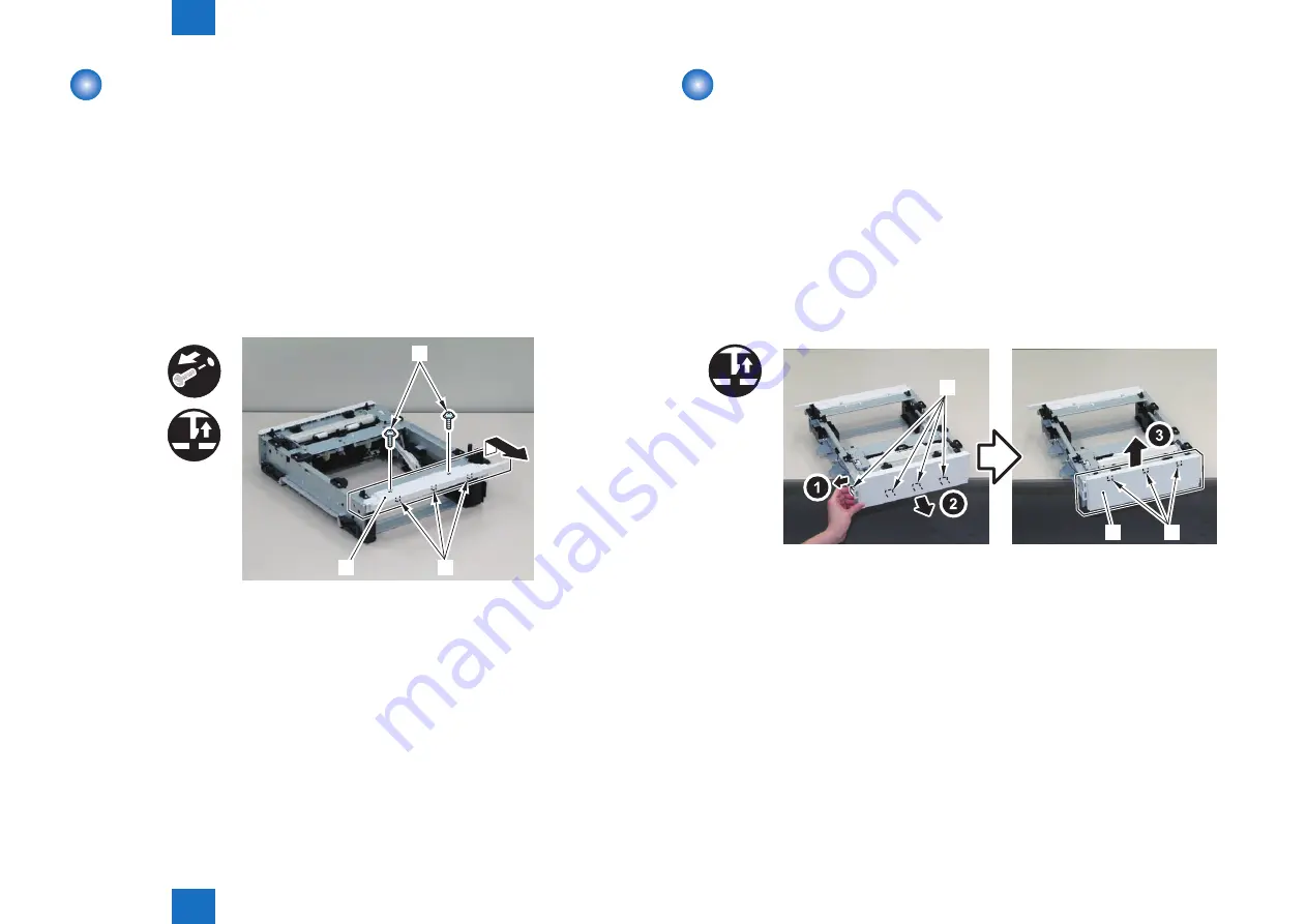
Removing the Front Cover
■
Preparation
1) Disconnect the host machine (printer).
2) Remove the cassette.
3) Remove the Right Cover.(Refer to page 3-4)
4) Remove the Left Cover.(Refer to page 3-6)
■
Procedure
1) Remove the Front Cover [1].
• 2 Screws [2]
• 3 Claws [3]
[3]
[1]
[2]
x2
x3
F-3-11
Removing the Rear Cover
■
Preparation
1) Disconnect the host machine (printer).
2) Remove the cassette.
3) Remove the Right Cover.(Refer to page 3-4)
4) Remove the Left Cover.(Refer to page 3-6)
■
Procedure
1) Remove the Rear Cover [1].
• 4 Claws [2]
• 3 Hooks [3]
x4
[2]
[3]
[1]
F-3-12
Содержание PF-701
Страница 5: ...1 1 Product Description Product Description Specifications Parts Name ...
Страница 7: ...2 2 Technical Reference Technical Reference Basic Operation Jam Detection ...
Страница 23: ...5 5 Troubleshooting Troubleshooting Outline of Electrical Components ...
Страница 25: ... Service Tools General Circuit Diagram Appendix ...