


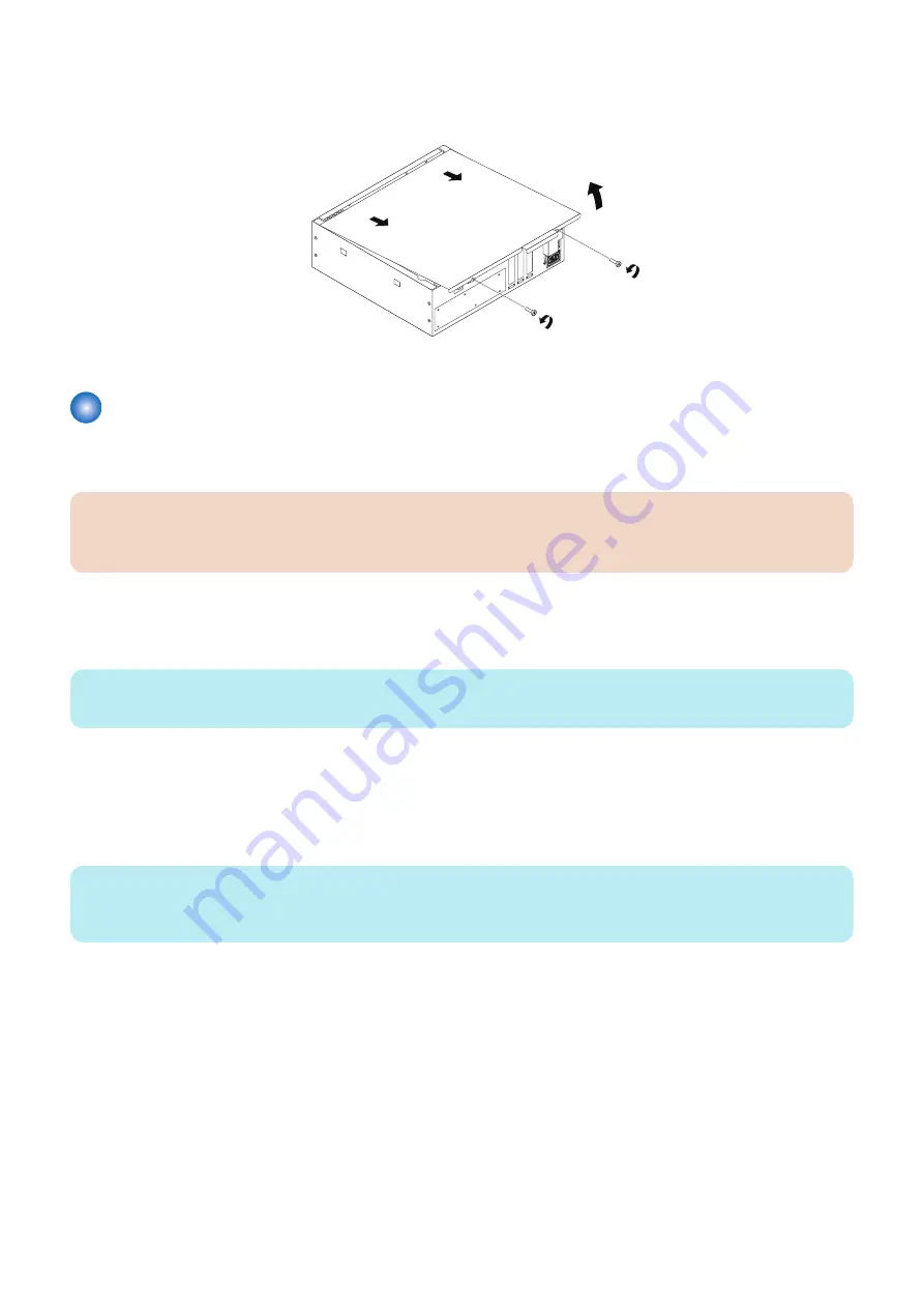
10. Raise the cover and slide it toward the connector panel of the chassis to remove it.
Set aside the cover so that you can replace it later.
The
imagePRESS Server
internal components are now accessible.
Figure 4:Removing the chassis cover
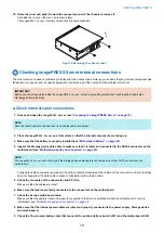
Checking imagePRESS Server internal connections
The most common causes of problems are faulty and loose connections. Before you conclude that any internal component has
failed, remove, inspect, and reseat all appropriate connections, and then verify that the problem still occurs.
IMPORTANT:
Before you touch any parts inside the
imagePRESS Server
, attach a grounding wrist strap. Touching the chassis also
discharges static electricity.
■ Check internal cable connections
1. Access and open the
imagePRESS Server
(see
“Accessing the imagePRESS Server” on page 18
).
NOTE:
Refer the label behind the chassis cover to check the cable connections.
2. Place the
imagePRESS Server
on a flat surface so that the internal components are facing up.
3. Make sure that the battery is properly installed (see
“Motherboard battery” on page 23
).
4. Inspect the Storage device data cable to make sure that it is intact and connected to the SATA0 connector on the
motherboard (see
“Motherboard parts and connectors” on page 26
).
NOTE:
The
imagePRESS Server
will not boot up if the Storage device data cable is connected to any other SATA connector on the
motherboard.
Faulty data cables are easily overlooked. Check the contact point between the cable and the connector to ensure that they
have not separated. If a data cable is suspect, substitute it with a tested cable.
5. Check the fan cables of the chassis fan and CPU fan.
Make sure that the cables are intact.
6. Make sure that cables are firmly connected to the connectors on the motherboard.
7. Check the Service switchboard cable.
Make sure that the cable is intact and properly connected to the Service switchboard and the motherboard. For more
information, see
“Motherboard parts and connectors” on page 26
8. Make sure that the internal power cables are intact and properly connected to the power supply, Storage device,
and motherboard.
9. Check the 10-pin power button cable that connects the printer interface board (J351) and the motherboard (J29).
3. REPLACING PARTS
19
Содержание P 400
Страница 7: ...Introduction 1 Introduction 2 Specifications 7...
Страница 16: ...Using the imagePRESS Server 2 Using the imagePRESS Server 11...
Страница 21: ...REPLACING PARTS 3 Replacing parts 16...
Страница 51: ...INSTALLING SYSTEM SOFTWARE 4 Installing system software 46...
Страница 73: ...TROUBLESHOOTI NG 5 Troubleshooting 68...


