background image

MONITORING

11

EN


Attaching the LCD Monitor


About the LCD Attachment Unit

Use the optional LA-V1 or LA-V2 LCD Attachment Unit to attach the LCD monitor to the handle unit or to 
the camera’s body itself. For details see the instruction manual of the camera being used.


Attaching the LCD Monitor to the Handle Unit

1.

Turn off the camera.

2.

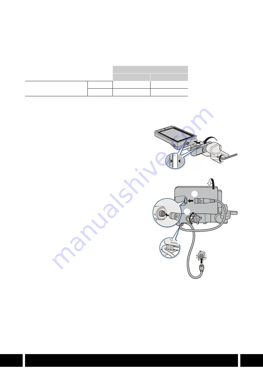
On the LCD attachment unit, rotate the LCD 
monitor mount in the direction of the locking knob 
to make the LCD monitor fixation bolt accessible.

3.

Attach the LCD monitor to the LCD monitor mount.

Align the 

Í

 marks on the monitor and monitor 

mount. If necessary, you can also mount the LCD 
monitor facing the other way around.

Tighten the LCD monitor fixation bolt using the hex 
wrench for 0.64 cm, 1/4" screws.

4.

Attach the LCD attachment unit to the handle unit.

Align the attachment mount on the LCD attachment 
unit to the handle unit’s front accessory mount.

Tighten the locking knob firmly.

5.

Rotate the LCD monitor 90 degrees toward the 
handle unit.

6.

Connect the LCD monitor to the camera’s VIDEO 
terminal using the UN-5 Unit Cable.

Align the 

Í

 marks on the cable’s plugs and 

terminals.

7.

Put the cable though the LCD attachment unit’s 
cable clamp.

If necessary, adjust the position of the cable so that 
it does not get in the picture or obstruct the view.

LCD Monitor

LM-V1

LM-V2

LCD Attachment Unit

LA-V1

N

LA-V2

N

Содержание LM-V1

Страница 1: ...ely hot cold and cause burns or injury when touched For accessories with screens viewfinders CAUTION Denotes the risk of injury Do not look at the screen or through the viewfinder for prolonged periods of time This may induce symptoms similar to motion sickness In such a case stop using the product immediately and rest for a while before resuming use For accessories with an eyecup CAUTIONS Follow ...

Страница 2: ...D Monitor 14 EVF V50 OLED Electronic Viewfinder 17 EVF V70 OLED Electronic Viewfinder 21 Added Functionality and Lens Compatibility 21 OU 700 Remote Operation Unit 25 EU V1 Expansion Unit 1 28 EU V2 Expansion Unit 2 35 MO 4E MO 4P B4 Mount Adapter 38 CM V1 EF Cinema Lock Mount Kit 38 PM V1 PL Mount Kit 43 Shooting Styles and Configuration 43 GR V1 Camera Grip 46 SU 15 Shoulder Support Unit 49 SG 1...

Страница 3: ...ded image and does not constitute a malfunction Unless specified otherwise power to the accessories is supplied by the camera Your camera may not support all the camera features and functions described in this guide Refer also to the instruction manual of the camera being used Some of the accessories and tools mentioned in the procedures in this guide may be supplied with some camera models Check ...

Страница 4: ...cessory EOS C100 Mark II EOS C200 EOS C200B EOS C500 Mark II EOS C700 all models 0 Communications GP E1 GPS Receiver N 6 GP E2 GPS Receiver N N N 7 WFT E6 WFT E8 Wireless File Transmitter N 9 Monitoring LM V1 LM V2 LCD Monitor N1 N 10 EVF V50 OLED Electronic Viewfinder N 14 EVF V70 OLED Electronic Viewfinder N N N 17 Added Functionality and Lens Compatibility RC V100 Remote Operation Unit N N N N ...

Страница 5: ...careful about using GPS functions where the operation of electronic devices is restricted The GPS information recorded with clips may contain data that can lead others to locate or identify you Be careful when sharing geotagged recordings with others or when uploading them to the Web Do not leave the receiver near strong electromagnetic fields such as near powerful magnets and motors The GPS infor...

Страница 6: ... GPS information to search and organize clips using Canon XF Utility Connecting and Activating the GPS Receiver 1 Turn off the receiver 2 Connect the receiver to the camera Use the USB cable supplied with the GP E2 3 Turn on the receiver The GPS function is activated The icon appears on the screen and will flash as the receiver tries to acquire satellite signals When satellite signals are correctl...

Страница 7: ...cation at the start of the recording You can have the camera s date and time settings adjusted automatically according to the information received from the GPS signal See the System Setup menu settings table in the instruction manual of the camera being used Initial GPS signal reception will take longer after replacing the receiver s battery or when first turning on the receiver after a prolonged ...

Страница 8: ...reless network or device via Wi Fi and use the camera s network functions For details about attaching and configuring the wireless transmitter refer to the instruction manual of the camera being used Do not place cables connected to the camera s terminals near the receiver Doing so may negatively affect the wireless signal attach directly System expansion terminal ...

Страница 9: ...ra being used An optional attachment unit is also required to attach the monitor to the camera Names of Parts 1 LCD panel with touch screen 2 FUNC main functions button Assignable button LCD LM V1 V2 1 3 MENU button 4 Joystick 5 MIRROR invert the displayed image button 6 CANCEL button 7 DISP display button Assignable button LCD LM V1 V2 2 8 LCD monitor s position alignment mark Í 9 Screw holes for...

Страница 10: ...t If necessary you can also mount the LCD monitor facing the other way around Tighten the LCD monitor fixation bolt using the hex wrench for 0 64 cm 1 4 screws 4 Attach the LCD attachment unit to the handle unit Align the attachment mount on the LCD attachment unit to the handle unit s front accessory mount Tighten the locking knob firmly 5 Rotate the LCD monitor 90 degrees toward the handle unit ...

Страница 11: ...sses Condensation may form on the surface of the screen when the temperature changes suddenly Wipe it with a soft dry cloth LCD Monitor LM V1 LM V2 Screen Type Color LCD Size 10 1 cm 4 0 in 10 9 cm 4 3 in Approximate dot count 1 230 000 2 760 000 Aspect ratio 16 9 Coverage 100 Touch screen Capacitive touch screen operation VIDEO terminal Exclusively for connecting the camera Operating temperature ...

Страница 12: ...etailed Measurements 119 90 4 7 75 40 3 0 35 99 1 4 12 85 0 51 36 40 1 4 0 63 cm 1 4 11 2 0 44 15 25 0 6 12 85 0 51 0 63 cm 1 4 11 2 0 44 132 9 5 2 86 6 3 4 37 5 1 5 47 4 1 9 13 0 51 13 0 51 15 1 0 59 mm inches 0 63 cm 1 4 11 2 0 44 0 63 cm 1 4 11 2 0 44 ...

Страница 13: ... camera The accessory will not work if it is attached while the camera is turned on 2 Remove the camera s expansion unit cover Remove the 2 bolts in the illustration using the hex wrench for M4 bolts Supplied Accessories Connector cover M4 hex socket head bolts x2 Eye cup Viewfinder cap 1 Viewfinder 2 Eye sensor 3 Diopter adjustment lever 4 Accessory fixation bolts M4 x2 5 Screw holes for fixation...

Страница 14: ...aching and Removing the Eye Cup Attach the eye cup so that it covers the rubber rim of the viewfinder To remove the eye cup pull it gently in a peeling off motion For left eye use attach the eye cup so that the protruding part faces the opposite side You can disable the eye sensor to turn on the viewfinder permanently See the Monitoring Setup menu settings table in the instruction manual of the ca...

Страница 15: ...ailed Measurements Screen 1280x720 resolution 1 770 000 dots Coverage 100 Operating temperature 0 C 40 C 32 F 104 F Dimensions W x H x D 61 x 90 x 99 mm 2 4 x 3 5 x 3 9 in Weight without connector cover 170 g 6 0 oz 60 5 2 4 99 3 9 40 1 6 60 2 2 4 44 4 1 7 89 8 3 5 6 8 mm inches ...

Страница 16: ...oystick that add functionality to the camera A clamp base is also required to attach the viewfinder to the camera About the Clamp Base Use the clamp base to attach the viewfinder to the handle unit or to the camera s body itself For details see the instruction manual of the camera being used Supplied Accessories Clamp rail unit Clamp base CL V2 optional Supplied with the camera EOS C700 all models...

Страница 17: ...on to return to the previous menu level 4 Viewfinder 5 Eye sensor 6 Dioptric adjustment ring 7 MAGN magnification button Assignable button EVF V70 3 8 FALSE COLOR button Assignable button EVF V70 4 9 Swing arm locking screw 10 Swing arm 11 VIDEO terminal 12 Screw hole for 1 4 20 mounting screws 25 mm 0 98 in deep 13 SELECT dial SET button 14 Joystick SET button 15 Swing arm slider 16 Screw hole fo...

Страница 18: ...nch for 0 64 cm 1 4 screws 7 Loosen the clamp rail locking screw 햸 8 Remove the end cap from the other arm of the clamp rail 햹 and insert the slider at the front of the clamp rail base into the clamp rail 햺 9 Attach the end cap that was removed in step 8 to the clamp rail 햻 10 Loosen the other swing arm s locking screw viewfinder side 햽 adjust the viewfinder to the desired position up down front b...

Страница 19: ... Attach the end cap that was removed in step 3 to the clamp rail 햶 6 Repeat steps 3 to 5 for the clamp rail s arm attached to the viewfinder Specifications All dimensions and weights are approximate Detailed Measurements Screen 1920x1080 resolution 6 220 000 dots Coverage 100 Operating temperature 0 C 40 C 32 F 104 F Dimensions W x H x D 243 x 88 x 185 mm 9 6 x 3 5 x 7 3 in Weight without connecto...

Страница 20: ... defined setup screen button 2 ALT alternative setup screen button 3 TC time code button 4 PLAY playback mode button 5 REC recording button 6 C key lock button 7 Joystick Push ÍÎ ÏÐ to move the AF frame face detection frame and magnification area When using the tracking function push ÍÎ ÏÐ to move the I mark to the desired subject and then press the joystick to start tracking When the second frame...

Страница 21: ...u can look at an external monitor that the camera is connected to If necessary you can remove the control display s protective cover inserting a fingernail or other thin object under the bottom center of the cover and pulling it After cleaning the control display place back the protective cover on the control display and push all four corners to secure it in place You can adjust the brightness of ...

Страница 22: ...ra 2 Attach the remote operation unit to the camera and connect the remote operation unit cable previous procedure Secure it firmly using the 2 supplied hex socket head bolts and the hex wrench for 0 64 cm 1 4 screws 3 Turn on the camera The OU 700 will turn on as well Specifications All dimensions and weights are approximate To disconnect the cable pull the plug s metal connector forward and then...

Страница 23: ...PATIBILITY 24 EN Detailed Measurements Front view 35 1 1 4 32 5 1 3 26 5 1 0 12 7 0 5 Top view Right side view 3 7 0 15 73 2 2 9 12 7 0 5 26 5 1 0 12 7 0 5 78 4 3 1 77 8 3 1 81 4 3 2 21 9 0 86 11 5 0 45 Rear view mm inches Bottom view ...

Страница 24: ...olts x2 1 Screw holes for fixation bolts x2 2 Accessory fixation bolts M4 x2 3 G LOCK SYNC OUT Genlock synchronization terminal The terminal s function Genlock input reference signal output is changed using the menu See the System Setup menu settings table in the instruction manual of the camera being used 4 REMOTE B terminal For connecting the optional RC V100 Remote Controller 5 Ethernet access ...

Страница 25: ...ecure the expansion unit in place First fasten the 2 fixation bolts you removed in step 2 to the top 햵 1 Then fasten the 2 supplied M4 fixation bolts to the rear 햵 2 Specifications All dimensions and weights are approximate G LOCK SYNC OUT terminal BNC jack 1 0 Vp p 75 Ω G LOCK Genlock setting input only SYNC OUT setting output only tri level HD signal The terminal s function can be changed using ...

Страница 26: ...ADDED FUNCTIONALITY AND LENS COMPATIBILITY 27 EN Detailed Measurements 68 7 2 7 40 1 6 61 7 2 4 44 4 1 7 91 9 3 6 81 5 3 2 mm inches ...

Страница 27: ...signable button Genlock synchronization advanced remote control circular 8 pin jack wired network Ethernet functionality additional audio inputs and controls lens communication 12 pin serial and power outputs Depending on the terminal function used power is supplied either from the camera or from a commercially available V mount battery attached to the EU V2 Supplied Accessories Connector cover M4...

Страница 28: ...haped battery mount V mount 10 D TAP terminal2 11 Screw holes for fixation bolts x2 12 DC OUT 24V 2A terminal2 13 G LOCK SYNC OUT Genlock synchronization terminal1 The terminal s function Genlock input reference signal output is changed using the menu See the System Setup menu settings table in the instruction manual of the camera being used 14 REMOTE B terminal1 For connecting the optional RC V10...

Страница 29: ...sion unit Remove the expansion unit s connector cover Align the ridges on the expansion unit with the protruding tabs on the camera and push the expansion unit straight all the way forward 4 Secure the expansion unit in place First fasten the 2 fixation bolts you removed in step 2 to the top 햵 1 Then fasten the 2 supplied M4 fixation bolts to the bottom 햵 2 You can remove all the terminals covers ...

Страница 30: ...ies When selecting commercially available batteries make sure the battery meets the following specifications and all the safety standards of the country region where it is used Closely follow the manufacturer s instructions regarding the use and maintenance of power sources V mount battery 12 V to 20 V DC Attaching a Battery 1 Make sure the camera is turned off 2 Align the V shaped wedge on the ba...

Страница 31: ... details about preparing the lens see the instruction manual of the camera being used 2 Attach a V mount battery to the expansion unit 0 31 3 Connect the lens s 12 pin cable to the LENS terminal on the expansion unit Power output Specifications Terminal pin layout DC OUT 24V 2A terminal Fischer 3 pin connector 24 V DC 2 0 A max D TAP terminal D Tap connector 50 W max Be sure to use the camera s po...

Страница 32: ...nput only SYNC OUT setting output only tri level HD signal The terminal s function can be changed using the camera s menu REMOTE B terminal Circular 8 pin jack for the optional RC V100 Remote Controller RS 422 interface Ethernet terminal Ethernet 1000BASE T compatible LENS terminal Circular 12 pin jack 12 pin serial interface DC OUT 24V 2A terminal Fischer 3 pin connector rated output 24 V DC maxi...

Страница 33: ...CTIONALITY AND LENS COMPATIBILITY 34 EN Detailed Measurements mm inches 6 5 0 26 116 5 4 6 53 4 2 1 40 1 6 117 4 4 6 146 9 5 8 138 1 5 4 11 3 0 44 18 0 71 57 2 2 53 2 1 26 7 1 1 M4 7 5 0 30 0 63 cm 1 4 7 5 0 30 ...

Страница 34: ...enses refer to the instruction manual of the camera being used Names of Parts Supplied Accessories Lens Cap Dust Cap Lens Support Bracket A Lens Support Bracket B The lens support bracket required depends on the lens used Check the following list of compatible lenses and make sure to use the correct lens support bracket Lens Support Bracket A HJ14ex4 3B HJ17ex7 6B Lens Support Bracket B HJ18ex7 6B...

Страница 35: ...on for attaching a lens 햶 5 Attach the lens to the adapter 햷 Align the index pin on the lens with the groove at the top part of the adapter Hold the lens horizontal while supporting it from beneath and turn the adapter s bayonet ring handle clockwise to lock the lens in place 햸 6 Attach the supplied lens support bracket to a commercially available lens support 7 Connect the lens s 12 pin interface...

Страница 36: ... camera 6 Remove the adapter from the camera Place the body cap back on the lens mount and the dust caps back on the adapter Specifications All dimensions and weights are approximate Detailed Measurements Lens configuration 4 elements in 3 groups Image circle 14 1 mm 0 6 in Multiplication factor 1 3x Operating temperature 0 C 40 C 32 F 104 F Dimensions diameter x length MO 4E 69 x 39 mm 2 7 x 1 5 ...

Страница 37: ... an EF cinema lock mount CM V1 kit or PL mount PM V1 kit Names of Parts CM V1 Supplied Accessories M3 hex socket head bolts x4 15 μm shims x6 20 μm shims x6 50 μm shims x4 100 μm shims x4 1 EF lens contacts 2 Mount handles 3 Screw holes for lens mount fixation bolts x4 4 EF lens mount index 5 EF S lens mount index 6 Lens locking pin 7 Lens mount contacts 2 3 4 1 3 2 6 5 7 ...

Страница 38: ...ttery back is attached to the camera remove them 2 Place the body cap on the camera s EF lens mount 3 Lay the camera on a flat surface with the lens mount facing up 4 Remove the 4 lens mount fixation bolts using the hex wrench for M3 bolts 5 Holding down the camera pull the camera s lens mount straight up to remove it 6 Attach the EF lens mount with Cinema Lock to the camera Align the lens mount c...

Страница 39: ...shown in the illustration Recommended torque 80 N cm Maximum torque 100 N cm Applying a torque exceeding the maximum torque may damage the camera and lens mount The camera is shipped with the flange back correctly adjusted For details about the initial thickness of the lens mount shims see Specifications in the instruction manual of the camera being used If the flange back need to be adjusted afte...

Страница 40: ...red dot on the lens with the red EF lens mount index mark on the camera EF S lenses Align the white square on the lens with the white EF S lens mount index mark on the camera 6 Without turning the lens turn the mount handle counter clockwise until it is tightened firmly PL Mount 1 Turn off the camera 2 Turn the bayonet ring counter clockwise to remove the body cap from the lens mount and remove an...

Страница 41: ...d Measurements Lens Mount Kit CM V1 PM V1 Dimensions diameter x length 107 x 31 mm 4 2 x 1 2 in 108 x 45 mm 4 3 x 1 8 in Weight 170 g 6 0 oz 345 g 12 2 oz 11 5 0 45 32 2 1 3 6 2 0 24 107 4 2 32 2 1 3 32 2 1 3 32 2 1 3 24 3 0 96 30 5 1 2 1 0 0 3 9 mm inches 19 5 0 77 32 2 1 3 13 0 51 10 8 3 4 3 32 2 1 3 32 2 1 3 32 2 1 3 32 3 1 3 45 3 1 8 1 0 0 3 9 ...

Страница 42: ...able button Names of Parts Supplied Accessories Grip attachment ring 1 Control dial 2 REC start stop recording button 3 Grip belt Adjust the grip belt so that you can reach the REC button on the camera grip with your index finger but still have a comfortable but secure grip 4 Joystick 5 FOCUS GUIDE button Assignable button Camera Grip 1 6 Rosette Compliant with ARRI rosettes 7 Locking screw 8 Grip...

Страница 43: ...a Make sure to insert the plug all the way in until the terminal is not visible If the plug is not correctly connected all the controls on the camera may be disabled 5 Attach the grip attachment ring 6 Return the camera to an upright position 7 Attach the camera grip to the camera aligning it at the desired angle and tighten the camera grip s locking screw Removing the Camera Grip 1 Turn off the c...

Страница 44: ...d Measurements Characteristics Modular unit can be attached at any of 24 positions 6º intervals includes limited recording controls Operating temperature 0 C 40 C 32 F 104 F Dimensions W x H x D 60 x 124 x 75 mm 6 1 x 4 6 x 3 0 in Weight without connector cover 260 g 9 2 oz 75 3 0 60 2 4 124 4 9 mm inches ...

Страница 45: ...er pad for optimal balance Names of Parts Supplied Accessories 15 mm rods x2 Rod stoppers x2 M4 hex socket head bolts x2 0 64 cm 1 4 hex socket head bolts x4 Bolt retainers x4 1 15 mm rod Compliant with ARRI s Lightweight Support 2 Rod clamp 3 Rosette Compliant with ARRI rosettes 4 Hex socket head bolt M4 5 Tripod base 6 Camera mount through holes 7 Shoulder pad screw 8 Shoulder pad 9 Shoulder sup...

Страница 46: ... support to the bottom of the camera 햵 and use the hex wrench for 0 64 cm 1 4 screws to partially tighten the 4 supplied fixation bolts for a provisional fix 7 Adjust the shoulder pad front back to the desired position and then fasten the bolts firmly 햶 Attaching the Accessory Rods 1 Pass the rods through the rod stoppers and use the hex wrench for M4 bolts to fasten one of the supplied M4 bolts t...

Страница 47: ...NG STYLES AND CONFIGURATION 48 EN Detailed Measurements 236 3 9 3 47 0 1 9 30 0 1 2 30 0 1 2 260 0 10 2 40 0 1 6 13 7 0 54 213 5 8 4 52 5 2 1 13 7 0 54 57 6 2 3 52 9 2 1 25 4 1 0 25 4 1 0 21 0 0 83 mm inches ...

Страница 48: ...ssignable button Names of Parts Supplied Accessories Grip connecting arm Hex wrench for M6 bolts 1 Grip zoom rocker Press gently for a slow zoom press harder for faster zooms 2 ONE SHOT AF focus automatically once button Assignable button Grip SG 1 1 3 Grip control dial 4 Rosette Compliant with ARRI rosettes 5 REC recording button 6 Joystick 7 IRIS aperture control button 8 IRIS aperture control s...

Страница 49: ... necessary and then fasten the bolt to secure the grip unit in place 5 Connect the grip unit s 12 pin interface cable to the LENS terminal on the camera or optional EU V2 Expansion Unit 2 햷 Align the O mark on the plug with the mark on the terminal You can adjust the cable s length Adjusting the 12 pin Interface Cable s Length 1 Remove the grip belt and use a coin or similar item to open the cable...

Страница 50: ...mensions and weights are approximate Detailed Measurements Dimensions W x H x D 220 x 148 x 148 mm 8 7 x 5 8 x 5 8 in Weight without connector cover 565 g 1 2 lb mm inches 20 2 0 8 33 1 1 3 33 1 1 3 77 5 3 1 70 7 2 8 166 5 6 6 53 0 2 1 127 9 5 0 30 0 1 2 30 0 1 2 ...

Отзывы: