


Chapter 2
2-8
2.5
Fixing System
2.5.1
After Disassembling
the Fixing Unit
0000-5361
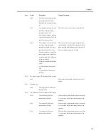
If you have loosened the adjusting screw used to
secure the upper frame and the lower frame of the
fixing unit in place (as when replacing a roller), be
sure to adjust the nip of the fixing roller as follows:
1) Turn the adjusting screw [1] at the front/rear so that
the length of the pressure spring is 31.5mm.
F-2-17
2) Fit the fixing unit in the machine, and execute the
following service mode to measure the nip:
COPIER>FUNCTION>FIXING>NIP-CHK
F-2-18
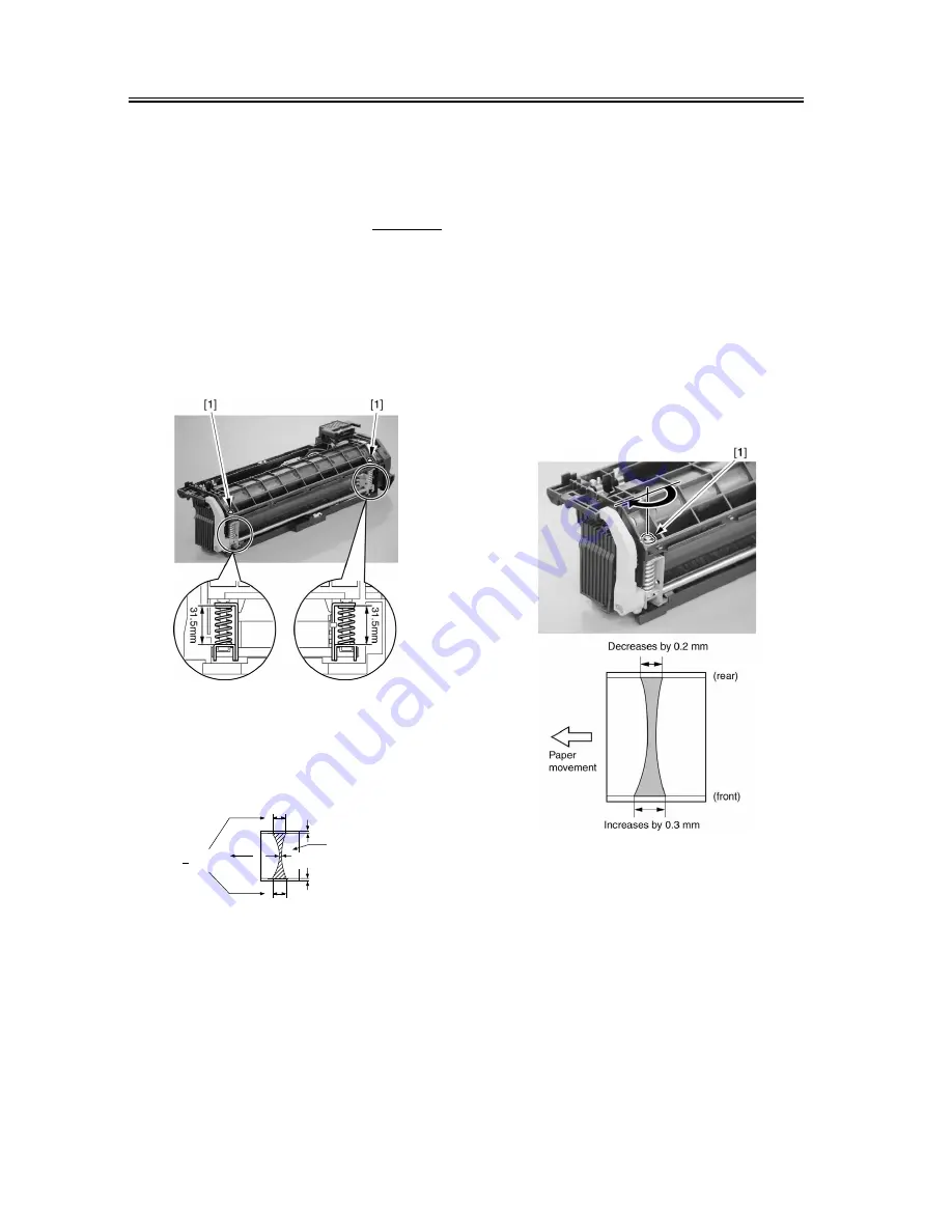
3) Adjust the balance between the front and the rear:
4) If the median value of the measured nip is toward
the lower limit of the standard, tighten the screw on
the side with a lower nip value at the edge.
MEMO:
A 1/2 turn of the screw shifts the nip balance by about
0.4 mm.
A 1/2 turn on the screw at the front will increase the
nip at the front by 0.3 mm, decreasing the nip at the
rear by 0.2 mm.
If the median value of the measured nip is toward the
higher limit of the standard, tighten the screw on the
side with a higher nip value at the edge.
If the nip needs adjustment while the nip balance is
correct, the adjusting screw both at the front and rear
may be given a 1/2 turn so that the nip may change by
about 0.3 mm.
F-2-19
Service Mode
COPIER>FUNCTION>FIXING>NIP-CHK
Use it to generate output for fixing nip width auto
measurement.
Paper
movement
Standard:
|a
c| = 0.5mm or less
1.5mm
c
a
b
Center
of paper
1.5mm
Standard:
8.75mm±0.25mm
(less than
5000 sheets)
9.25mm±0.25mm
(5000 sheets
or more)
Содержание iR C3200 Series
Страница 1: ...Dec 3 2004 Portable Manual iR C3200 Series iR C3220N PRT ...
Страница 2: ......
Страница 6: ......
Страница 10: ......
Страница 11: ...Chapter 1 Maintenance and Inspection ...
Страница 12: ......
Страница 14: ......
Страница 22: ...Chapter 1 1 8 ...
Страница 23: ...Chapter 2 Standards and Adjustments ...
Страница 24: ......
Страница 26: ......
Страница 40: ...Chapter 2 2 14 ...
Страница 41: ...Chapter 3 Error Code ...
Страница 42: ......
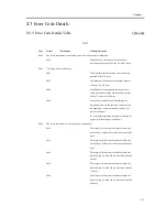
Страница 43: ...Contents Contents 3 1 Error Code Details 3 1 3 1 1 Error Code Details Table 3 1 ...
Страница 44: ......
Страница 63: ...Chapter 4 User Mode Items ...
Страница 64: ......
Страница 66: ......
Страница 79: ...Chapter 5 Service Mode ...
Страница 80: ......
Страница 82: ......
Страница 121: ...Chapter 6 Outline of Components ...
Страница 122: ......
Страница 124: ......
Страница 134: ...Chapter 6 6 10 F 6 6 PLG1 ELCB1 SP1 H4 H3 H2 H1 H1 H2 LA1 ...
Страница 138: ...Chapter 6 6 14 ...
Страница 139: ...Chapter 7 System Construction ...
Страница 140: ......
Страница 142: ......
Страница 157: ...Chapter 8 Upgrading ...
Страница 158: ......
Страница 160: ......
Страница 168: ...Chapter 8 8 8 ...
Страница 169: ...Dec 3 2004 ...
Страница 170: ......


