Chapter 1
8
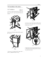
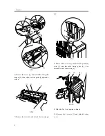
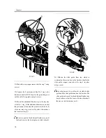
(binding; M4x6).
F-1-15
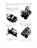
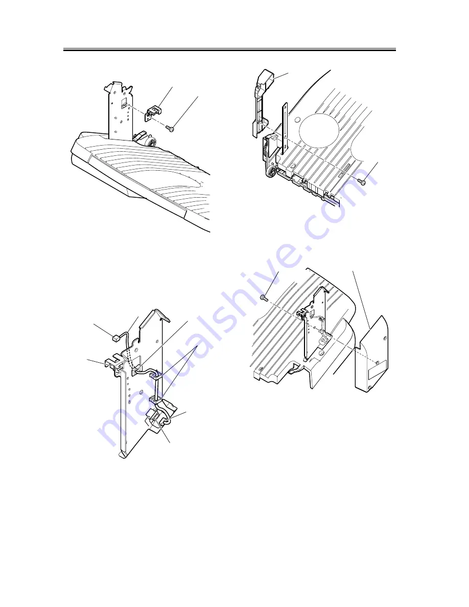
16) Route the sensor cable [3] through the edge saddle
[1] and the cable clamps [2]. Join the connector [4] to
the sensor [5] and the another connector [6] to the
connector [7] of the No. 1 tray.
F-1-16
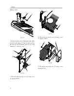
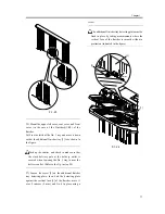
17) Mount the front tray stay cover [1] Using a screw
[2] (tapping; M4x12).
F-1-17
18) Mount the rear tray stay cover [1] using a screw
[2] (tapping; M4x12).
F-1-18
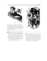
19) Mount the sensor unit cover [1] using a screw
(binding; M4x6).
[1]
[2]
[6]
[2]
[4]
[7]
[1]
[5]
[3]
[1]
[2]
[2]
[1]
Содержание Inner Finisher Additional Tray-A1
Страница 1: ...Dec 10 2003 Installation Procedure Finisher Sorter DeliveryTray Additional Finisher Tray A1 ...
Страница 2: ......
Страница 6: ......
Страница 8: ...Contents ...
Страница 9: ...Chapter 1 Installation Procedure ...
Страница 12: ...Chapter 1 4 3 Disconnect the host machine s power plug from the power outlet ...
Страница 21: ...Dec 10 2003 ...
Страница 22: ......


