Canon imageRUNNER 2270 Скачать руководство пользователя страница 99

Chapter 2

2-21

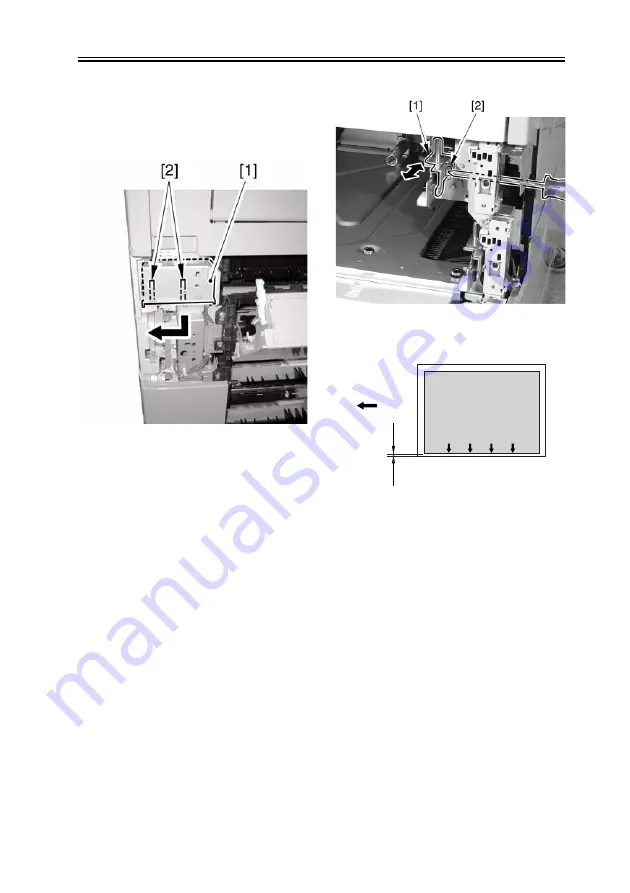
6) Remove the 2 claws [2], and detach the

grip (right front) [1] in the direction of
the arrow.

F-2-46

7) Loosen the fixing screw [2] of the

adjusting plate [1].

8) While referring to the index you

checked in step 5), move the adjusting
plate back and forth. Moving the
adjusting plate toward the rear of the
machine will increase the left margin L1
of the image.

F-2-47

F-2-48

[1]Paper feed direction

9) Tighten the fixing screw.
10) Fit the cassette 1 back in.
11) Make a copy, and check to be sure that

the left margin of the image on paper
picked up from the cassette 1 is 2.5 +/-
1.5 mm.

12) Fit the grip (right front) back in.
13) Attach the right cover of the machine.
*Adjusting the Cassette 2
6) Loosen the fixing screw [2] of the

adjusting plate [1].

7) While referring to the index you

checked in step 5), move the adjusting

image

L1

[1]

Содержание imageRUNNER 2270

Страница 1: ...SERVICE MANUAL imageRUNNER 2270 2870 3570 4570 COPYRIGHT 2004 CANON INC CANON imageRUNNER 2270 2870 3570 4570 REV 0 PRINTED IN U S A SEPT 2004 REV 0 SM cover qxd 9 20 2004 2 17 PM Page 1 ...

Страница 2: ... need arises In the event of major changes in the contents of this manual over a long or short period Canon will issue a new edition of this manual The following paragraph does not apply to any countries where such provisions are inconsistent with local law Trademarks The product names and company names used in this manual are the registered trademarks of the individual companies Copyright This ma...

Страница 3: ...quiring care to avoid combustion fire Indicates an item prohibiting disassembly to avoid electric shocks or problems Indicates an item requiring disconnection of the power plug from the electric outlet Indicates an item intended to provide notes assisting the understanding of the topic in question Indicates an item of reference assisting the understanding of the topic in question Provides a descri...

Страница 4: ...sed to indicate Low The voltage value however differs from circuit to circuit In addition the asterisk as in DRMD indicates that the DRMD signal goes on when 0 In practically all cases the internal mechanisms of a microprocessor cannot be checked in the field Therefore the operations of the microprocessors used in the machines are not discussed they are explained in terms of from sensors to the in...

Страница 5: ...5 1 2 1 Names of Parts 1 15 1 2 2 Using the Machine 1 19 1 2 3 User Mode Items 1 25 1 2 4 Maintenance by the User 1 43 1 2 5 Safety 1 47 1 2 6 Product Specifications 1 49 1 2 7 Function List 1 51 Chapter 2 Installation 2 1 Making Pre Checks 2 1 2 1 1 Selecting the Site of Installation 2 1 2 1 2 Before Starting the Work 120V 2 3 2 2 Unpacking and Installation 2 8 2 2 1 Unpacking and Removing the Pa...

Страница 6: ...d Reader 2 31 2 6 1 Points to Note 2 31 2 6 2 Checking the Contents 2 31 2 6 3 Installation Procedure 2 32 2 6 4 Installation in a NetSpot Accountant NSA Environment 2 37 2 7 Installing the NE Controller 2 39 2 7 1 Installing the NE Controller A1 2 39 Chapter 3 Basic Operation 3 1 Construction 3 1 3 1 1 Functional Construction 3 1 3 1 2 Major PCB Wiring diagram 3 2 3 2 Basic Sequence 3 4 3 2 1 Bas...

Страница 7: ...or the PDL Function 4 23 4 7 Parts Replacement Procedure 4 24 4 7 1 Main Controller PCB 4 24 4 7 2 SDRAM 4 26 4 7 3 Boot ROM 4 27 4 7 4 HDD 4 27 Chapter 5 Original Exposure System 5 1 Construction 5 1 5 1 1 Specifications Control Mechanisms and Functions 5 1 5 1 2 Major Components 5 3 5 1 3 Construction of the Control System 5 5 5 1 4 Reader Controller PCB 5 6 5 2 Basic Sequence 5 8 5 2 1 Basic Se...

Страница 8: ...c Sequence 6 6 6 3 Various Controls 6 7 6 3 1 Controlling the Laser Activation Timing 6 7 6 3 2 Controlling the Intensity of Laser Light 6 10 6 3 3 Controlling the Laser Scanner Motor 6 10 6 3 4 Controlling the Laser Shutter 6 11 6 4 Parts Replacement Procedure 6 12 6 4 1 Laser Scanner Unit 6 12 Chapter 7 Image Formation 7 1 Construction 7 1 7 1 1 Specifications of the Image Formation System 7 1 7...

Страница 9: ...he Toner Cartridge 7 19 7 8 4 Toner Supply Control 7 20 7 8 5 Recovery Sequence 7 21 7 8 6 Toner Level Detection 7 22 7 9 Transfer Unit 7 23 7 9 1 Outline of the Transfer Unit 7 23 7 9 2 Controlling the Transfer Bias 7 24 7 9 3 Cleaning 7 25 7 9 4 Separation Mechanism 7 25 7 10 Transfer Mechanism 7 26 7 10 1 Transfer Guide Bias 7 26 7 11 Photosensitive Drum Cleaning 7 27 7 11 1 Outline 7 27 7 11 2...

Страница 10: ...inisher S1 copy tray 8 12 8 1 10 Diagram of Paper Paths w Finisher Q3 Saddle Finisher Q4 8 13 8 1 11 Arrangement of Sensors 8 14 8 1 12 Arrangement of Sensors 8 15 8 1 13 Route of Drive 8 17 8 1 14 Route of Drive 8 18 8 2 Basic Sequence 8 20 8 2 1 Basic Sequence 8 20 8 2 2 Increase in Speed 8 21 8 2 3 Increase in Speed 8 24 8 3 Detecting Jams 8 26 8 3 1 Delivery Jams 8 26 8 3 2 Stationary Jams 8 2...

Страница 11: ...r 1 8 83 8 8 6 Cassette Pick up Motor 2 8 85 8 8 7 Cassette Size Sensor 8 87 8 8 8 Cassette Retry Paper Sensor 8 89 8 8 9 Cassette Paper Sensor 8 90 8 8 10 Cassette Paper Level Sensor A B 8 90 8 8 11 Slide Resistor 8 91 8 8 12 Cassette Pickup Solenoid 8 92 8 8 13 Cassette Size Sensor Relay PCB 8 95 8 8 14 Manual Tray Assembly 8 96 8 8 15 Manual Feed Unit 8 96 8 8 16 Manual Pickup Roller 8 98 8 8 1...

Страница 12: ...nctions 9 10 9 4 2 Detecting an Error 9 11 9 5 Parts Replacement Procedure 9 13 9 5 1 Fixing Unit 9 13 9 5 2 Pressure Roller 9 16 9 5 3 Cleaning Roller 9 21 9 5 4 Fixing Film 9 22 9 5 5 Internal Delivery Sensor 9 24 9 5 6 Fixing Film Sensor 9 27 Chapter 10 External and Controls 10 1 Control Panel 10 1 10 1 1 Overview 10 1 10 1 2 LCD Indication Processing 10 2 10 1 3 Adjustment of the LCD Contact 1...

Страница 13: ... 30 10 5 8 Control Panel CPU PCB 10 31 10 5 9 All Night Power Supply PCB 10 32 10 5 10 Controller Power Supply PCB 10 32 10 5 11 Option Power Supply PCB 10 34 10 5 12 High Voltage PCB 10 35 10 5 13 Exhaust Fan 10 47 10 5 14 Motor of Main Drive Assembly 10 49 10 5 15 Fixing Driver Motor 10 51 10 5 16 Right Door 10 52 10 5 17 Circuit Braker 10 54 Chapter 11 MEAP 11 1 Overview 11 1 11 2 MEAP Counter ...

Страница 14: ...g System 13 9 13 2 1 After Replacement of the CIS 13 9 13 2 2 After Replacing the Reader Controller PCB or Initializing the RAM 13 9 13 3 Laser Exposure System 13 12 13 3 1 After Replacing the Laser Scanner Unit 13 12 13 4 Image Formation System 13 13 13 4 1 After Replacing the Developing Unit 13 13 13 4 2 After Replacing the Drum Unit APVC correction 13 13 13 5 Electrical Components 13 14 13 5 1 ...

Страница 15: ... Clutch Solenoid 14 24 14 3 2 Motor 14 25 14 3 3 Fan 14 29 14 3 4 Sensor 14 30 14 3 5 Switch 14 37 14 3 6 Lamps Heaters and Others 14 38 14 3 7 PCBs 14 41 14 3 8 Variable Resistors VR Light Emitting Diodes LED and Check Pins by PCB 14 45 Chapter 15 Self Diagnosis 15 1 Error Code Table 15 1 15 1 1 Error Code 15 1 15 2 Error Code Details 15 5 15 2 1 Error Code Details 15 5 15 2 2 E602 in Detaill 15 ...

Страница 16: ...16 1 7 4th Item Screen 16 6 16 2 DISPLAY Status Display Mode 16 7 16 2 1 COPIER 16 7 16 2 2 FEEDER 16 17 16 3 I O I O Display Mode 16 18 16 3 1 Outline 16 18 16 3 2 DC CON 16 19 16 3 3 R CON 16 23 16 3 4 FEEDER 16 26 16 3 5 SORTER 16 27 16 4 ADJUST Adjustment Mode 16 40 16 4 1 COPIER 16 40 16 4 2 FEEDER 16 52 16 4 3 SORTER 16 53 16 5 FUNCTION Operation Inspection Mode 16 54 16 5 1 COPIER 16 54 16 ...

Страница 17: ...Contents 16 8 1 COPIER 16 116 Chapter 17 Service Tools 17 1 Special Tools 17 1 17 2 Oils and Solvents 17 3 ...

Страница 18: ...Chapter 1 Introduction ...

Страница 19: ...cessory System Configuration 3 1 7 1 1 5 Pickup Original Handling Accessories System Configuration 1 9 1 1 6 Printing Transmitting Accessories System Configuration 1 11 1 1 7 List of Print Transmission Optional Functions 1 12 1 2 Product Specifications 1 15 1 2 1 Names of Parts 1 15 1 2 2 Using the Machine 1 19 1 2 3 User Mode Items 1 25 1 2 4 Maintenance by the User 1 43 1 2 5 Safety 1 47 1 2 6 P...

Страница 20: ...ssing e g stapling punching is needed delivery accessory system configuration 1 if delivery processing is limited to stapling punching delivery accessory system configuration 2 if delivery processing is limited to 3 way delivery delivery accessory system configuration 3 1 1 2 Delivery Accessory System Configuration 1 0006 6221 The following shows a typical system configuration of this type Remarks...

Страница 21: ...Chapter 1 1 2 iR 3570 iR 4570 F 1 1 6 2a 1a 3a 6a 4a 5a 1 3 4 2 5 ...

Страница 22: ...M1 N1 P1 3a Installation Procedure Installation of the Punch Unit L1 M1 N1 P1 4 Buffer Path Unit E1 4a Instruction Sheet indicating references 5 Expansion Delivery Kit A1 5a Installation Procedure Installation of the Expansion Deliver Kit A1 6 Accessories Power Supply P2 needed when installing 1 through 4 standard with 120 230V model 6a Installation Procedure Installation of the Accessories Power ...

Страница 23: ...ivery Kit A1 comes as standard with the following models Function provided Accessory needed saddle binding Saddle Finisher Q4 Accessories Power Supply P2 Buffer Path Unit E1 Expansion Delivery Kit A1 Function provided Accessory needed punching Finisher Q3 or Saddle Finisher Q4 Accessories Power Supply P2 Buffer Path Unit E1 Expansion Delivery Kit A1 Punch Unit L1 M1 N1 P1 ...

Страница 24: ...S1 1a Installation Procedure Installation of the Finisher S1 2 Expansion Delivery Kit A1 2a Installation Procedure Installation of the Delivery Kit A1 3 Copy Tray J1 3a Installation Procedure Installation of the Copy Tray J1 3a 1a 2a 6a 4 4a 6 3 2 5a 5 1 ...

Страница 25: ...er Kit Q1 R1 S1 T1 5a Installation Procedure Installation of the Inner Puncher Kit Q1 R1 S1 T1 6 Finisher Additional Tray B1 6a Installation Procedure Installation of the Finisher Additional Tray B1 Function provided Accessory needed 2 way delivery stapling Finisher S1 Accessories Power Supply P2 Expansion Delivery Kit A1 Copy Tray J1 Function provided Accessory needed 3 way delivery stapling Fini...

Страница 26: ... following shows a typical system configuration of this type Remarks The Expansion Delivery Kit A1 comes as standard with the following models Function provided Accessory needed punching Finisher S1 Accessories Power Supply P2 Expansion Delivery Kit A1 Inner Puncher Kit Q1 R1 S1 T1 ...

Страница 27: ...llation of the Inner 2 Way Tray D1 2 Expansion Delivery Kit A1 powered by the printer unit not requiring the Accessories Power Supply P2 2a Installation Procedure Installation of the Expansion Delivery Kit A1 3 Copy Tray J1 3a Installation Procedure Installation of the Copy Tray J1 3a 3 1a 2a 2 1 ...

Страница 28: ...Chapter 1 1 9 1 1 5 Pickup Original Handling Accessories System Configuration 0006 6254 The following shows a typical system configuration F 1 4 9 9a 1a 4a 10a 8a 6a 6 1 2 4 5 8 7 10 3 ...

Страница 29: ...ing Kit B1 6 2 Cassette Pedestal Y2 6a Installation Procedure Installation of the 2 Cassette Pedestal Y2 7 Envelope Cassette C1 100V 8 Envelope Cassette Attachment C1 115 200V 8a Installation Procedure Installation of the Envelope Cassette Attachment C1 9 Accessories Power Supply P2 required when installing the Side Paper Deck Q1 4 standard with 120 230V model 9a Installation Procedure Installatio...

Страница 30: ...1 5 1 UFR II Printer Kit E3 P BootROM 2 Printer Kit E2 H BootROM for 230 V model 3 Multi PDL Printer Kit E1 N BootROM 4 Expansion Bus B1 5 USB Application Interface Board D1 6 iR256MB Expansion RAM B1 standard with 120V model 7 iR Security Kit A2 License 8 Super G3 Fax Board Q1 9 Multi FAX Board D1 for 120 V model 1 7 10 11 4 5 6 8 9 12 13 2 3 ...

Страница 31: ...ssion Optional Functions 230 V model The following is a brief explanation of the functions expected of the accessories for details see the chapters that follow UFR II print function UFR II Printer Kit E3 P BootROM UFR II PCL PS print function Multi PDL Printer Kit E1 N BootROM Send function Univrsal Send Kit B1 Fax function 1 line Super G3 Fax Board Q1 Fax function 2 line Multi FAX Board D1 MEAP a...

Страница 32: ...pplication is installed the device will not operate E604 0001 is displayed When you want to enable use of MEAP authentication and MEAP application operation need for iR256 MB Expansion RAM B1 installed MEAP function H boot N boot memory expansion needed without memory expansion the device will not operate E744 is displayed MEAP application USB connection function USB Application Interface Board D1...

Страница 33: ...Chapter 1 1 14 Encryption PDF function Searchable PDF function Univrsal Send Kit B1 Universal Send PDF Encryption Kit B1 Universal Send Searchable PDF Kit A1 iR256MB Expansion RAM B1 ...

Страница 34: ...s 0007 2860 F 1 6 1 ADF reading glass retainer 2 DADF 3 Reader cover front 4 Control panel 5 Support cover right 6 Support cover 7 Delivery tray right cover 8 Delivery tray 9 Inside right cover 10 Front cover unit 11 Cassette 1 12 Cassette 2 1 3 2 10 11 12 13 14 16 18 5 4 6 7 9 8 15 17 ...

Страница 35: ... cover lower 18 Delivery tray rear cover F 1 7 19 Reader over right 20 Copyboard glass 21 Reader cover rear 22 Face over iR3570 4570 23 Rear cover 24 Right cover rear 25 Manual feed pickup tray 26 Right cover lower front 27 Right door unit 28 Delivery cover 29 Right cover upper 19 20 21 22 24 25 26 27 29 23 28 ...

Страница 36: ...Chapter 1 1 17 1 2 1 2 Cross Section 0007 9223 iR2270 iR2870 model F 1 8 7 21 22 23 24 27 28 1 2 3 11 13 15 16 17 18 19 20 4 29 26 5 6 12 25 8 9 10 14 ...

Страница 37: ...Chapter 1 1 18 iR3570 iR4570 model F 1 9 7 21 22 23 24 27 28 1 2 3 11 13 15 16 17 18 19 20 4 29 26 5 6 12 25 8 9 10 14 ...

Страница 38: ...board glass 18 Vertical path roller 1 4 Toner bottle 19 Feed roller cassette 1 5 Drum unit 20 Separation roller cassette 1 6 Drum cleaner assembly 21 Vertical path roller 2 7 Delivery roller 22 Feed roller cassette 2 8 Fixing outlet roller 23 Separation roller cassette 2 9 Fixing film unit 24 Pickup roller cassette 2 10 Pressure roller 25 Primary charging roller 11 Duplex feed roller 1 26 Developi...

Страница 39: ...ch Do not turn off the main power while the progress bar is displayed indicating that the HDD is being accessed Otherwise the HDD can suffer a fault E602 1 2 3 Display Contrast Guide Reset ON OFF Clear Start Stop Error Main Power 1 2 3 4 5 6 7 8 9 0 1 2 3 Start Memory Additional Function ...

Страница 40: ...nel power switch before turning off the main power switch When Using the Print Function When Receiving or Transmitting a Fax Before using the main power switch check to be sure that the Execute Memory lamp on the control panel is off Turning off the main power switch while an operation is under way can cause loss of data ...

Страница 41: ...pter 1 1 22 F 1 12 At Time of Downloading Do not turn off the main power switch while downloading is under way Otherwise the machine may not be able to operate normally C 0 9 Error Main Power Start Memory ...

Страница 42: ...Chapter 1 1 23 F 1 13 ON OFF ...

Страница 43: ...ol panel power switch 11 ID key 4 Counter Check key 12 Image contrast adjustment dial 5 Stop key 13 User Mode key 6 Start key 14 Help key 7 Main power lamp 15 Touch panel 8 Error lamp 1 2 3 Display Contrast Additional Function ON OFF Clear Error Start Memory Main Power 1 2 3 4 5 6 7 8 9 0 2 1 3 4 5 6 7 8 9 10 11 12 13 14 15 ...

Страница 44: ... post auto reset function use do not use set order of functions copy transmit Box remote scan or functions appearing on tab change order by Up Down key set order of function groups group A MEAP group B enable disable buzzer input sound ON OFF invalid input sound ON OFF supply alert sound ON OFF warning sound ON OFF job end sound ON OFF indicate paper level message ON OFF inch input ON OFF if US on...

Страница 45: ...tray B receive fax 1 fax 2 w inner tray tray A host middle tray lower tray B host middle tray upper tray A copy box printer receive fax other tray B copy box printer receive fax other fine setup for receive fax tray A receive fax1 fax 2 tray B receive fax 1 fax 2 w inner tray No 3 tray tray A host middle tray lower tray B host middle tray upper tray C No 3 tray tray A copy Box printer receive fax ...

Страница 46: ...3 tray tray A copy Box printer receive fax other tray B copy Box printer receive fax other fine setup for receive fax tray A receive fax 1 fax 2 tray B receive fax 1 fax 2 Finisher S1 option tray No 3 tray tray A finisher optional tray tray B finisher output tray tray C No 3 tray tray A copy Box printer receive fax other tray B copy Box printer receive fax other tray C copy Box printer receive fax...

Страница 47: ...ve fax receive if fax only receive fax fax fine setup for receive fax only if w fax if fax is 1 line fax 1 fax 2 fax Finisher S1 w o output option special tray items not indicated w o output option tray tray A host middle tray tray A copy Box printer receive fax other 1 output target therefore special tray items not indicated assign print priority copy 1 2 3 printer 1 2 3 Box 1 2 3 receive fax 1 2...

Страница 48: ...er auto cassette 1 through 5 number of prints 1 through 2000 sorter sort group staple sort shift sort shift group rotation sort rotation group punch Z fold duplex on open to right open to top bottom off delete file after print ON OFF merge file ON OFF switch display language ON OFF reverse screen color ON OFF between job shift ON OFF put sheet between jobs On select source of paper OFF put sheet b...

Страница 49: ...eset time 0 disable 1 2 9 min in 1 min increments set weekly timer 00 00 to 23 59 in 1 min increments everyday from Sun to Sat Mode Description zoom fine adjust XY individually 1 0T to 1 0 in 0 1 increments 0 center bind staple edging w saddle finisher Start key center bind position change w saddle finisher size A3 11x17 B4 LGL A4R LTRR position 2 0 mm to 2 0 mm in 0 35 mm increments 0 mm density ...

Страница 50: ...ption ON OFF toggle fax settings fax transmission result report only if error ON OFF show transmission report ON OFF fax communication control report print automatically every 40 communications print at specified time ON OFF set time 00 00 to 23 59 separate transmission and reception ON OFF toggle fax reception result report only if error ON OFF fax Box reception report list print transmission add...

Страница 51: ...ity status print sample print Mode Description set system administrator info system administrator group ID 7 characters max system administration ID set 7 characters system administrator name 32 bytes mail address 64 bytes contact 32 bytes comment 32 bytes group ID control group ID control ON OFF register ID No register edit delete limit function count control reset count print all clear print wit...

Страница 52: ... memory reception end time everyday day of week none enable disable remote UI ON OFF use SSL ON OFF limit addresses address book ID No 7 characters max address book access No control ON OFF limit new addresses ON OFF set device info device name 32 characters installation site 32 characters transfer setup reception method conditions ON OFF register register transfer without condition e mail priorit...

Страница 53: ...l info delete auto distribution setup everyday day of week none user mode setting ON OFF network setting include do not include group ID ON OFF address book ON OFF manual distribution setup user mode setting ON OFF network setup include do not include group ID ON OFF address book ON OFF user mode sync level ON OFF recover data user mode settings group ID address book limit reception by function us...

Страница 54: ...rence key 2 none individual modes auto sort ON OFF auto vertical horizontal rotation ON OFF print photo mode ON OFF change standard mode register reset at time of shipment 1 set auto paper auto density auto image quality local printer reset copy settings Do you really want to reset yes no auto sort on face down delivery on preference key none Mode Description set common communications settings reg...

Страница 55: ...ers x 2 lines max confirm transmission of coded PDF file ON OFF PDF OCR setup original orientation auto detection ON OFF number of OCR characters for file name 1 through 24 initial transmission screen routine task button one touch button new address source record add do not add display location inside image outside image display target abbreviation ON OFF telephone No mark FAX TEL communication mo...

Страница 56: ...ming ON OFF source No notice ON OFF abbreviate select line type 120V 230V push tone dial pulse 10 PPS 100 V 20 pps 10 pps push tone 100V 20pps 10pps push tone volume control alarm sound level 0 to 8 4 0 to 8 4 off hook alarm ON OFF set fax transmission function ECM transmission ON OFF set pause length 1 to 15 sec 4 to 11 sec 3 to 6 sec auto re dial ON OFF number of redials 100V 1 15 2 120V 1 10 2 ...

Страница 57: ...imes OFF remote reception on remote reception ID 00 to 99 25 OFF auto reception switch over on length of ring 1 to n sec OFF source record G4 add do not add source record position inside image outside image set fax expansion line register user telephone No 20 characters max register user abbreviation 24 characters max select line type 20 pps 10pps push tone select transmission line line 1 priority...

Страница 58: ...tion set up register user box select box 0 to 99 register box name 24 characters max ID NO 0 to 99999999 file auto delete 0 no 1 2 3 6 12 hr 1 2 3 7 30 days URL transmissions setup select e mail address reset print photo mode ON OFF standard mode for read setup register reset set register fax box select box 0 49 register box name 24 characters max ID No 0 to 9999999 URL transmission setup select e...

Страница 59: ...meout 5 to 300 15 sec disable RIP yes no sorter do not use sort rotation sort rotation group shift sort shift group staple sort punch disable top bottom left right booklet print disable open to left open to right middle bind enable disable transparency interleaf disable white sheet printed sheet print in sets print in sets enable disable print position 5 locations upper left lower left upper right...

Страница 60: ...Chapter 1 1 41 auto switchover LIPS enable disable ESC P enable disable 15577 enable disable HP GL enable disable connection recognition enable disable printer settings rest yes no Mode Description ...

Страница 61: ...acters max pause tone backspace space ISDN sub address F Net DT R PIN sub settings Sub Settings F code 20 characters max password 20 characters max ECM transmission ON OFF transmission speed 33600 bps 14400bps 9600 bps 4800 bps international transmission domestic international transmission 1 international transmission 2 international transmission 3 communication mode G4 to G3 G3 only e mail target...

Страница 62: ...pi 600x600dpi file register address register name 24 characters register name 24 superscript characters protocol FTP Windows SMB Netware IPX host name 128 characters path to folder 128 characters user name FTP Netware IPX 24 characters Windows SMB 15 characters password FTP Netware IPX 24 characters Windows SMB 14 characters group register target register name 24 characters register name 24 supers...

Страница 63: ... from pull down menu LDAP server already registered search condition name 128 characters e mail 128 characters fax 128 characters fine search server to search select from pull down menu LDAP server already registered search conditions name email fax organization organization based including next not including next identical to next not identical to next starts with next ends with next name organiz...

Страница 64: ...Chapter 1 1 45 F 1 15 F 1 16 ...

Страница 65: ...e sure also to ask the user to keep a record of checks Inspection Procedure 1 Turn on the main power switch 2 Push he test button 1 of the leakage breaker with the tip of a ball point pen 2 3 Check to make sure that the breaker switch shifts to the OFF side and the power is cut F 1 17 4 Turn off the main power switch 5 Shift the breaker switch 1 back to the ON position F 1 18 ...

Страница 66: ...Chapter 1 1 47 If the breaker switch has stopped between ON and OFF be sure to shift it to OFF first and then back to ON F 1 19 F 1 20 6 Turn on the main power switch ...

Страница 67: ... Devices and Radiological Health of the US Food and Drum Administration put into force regulations concerning laser products on August 2 1976 These regulations apply to laser products manufactured on and after August 1 1976 and the sale of laser products not certified under the regulations is banned within the Untied States The label shown here indicates compliance with the CDRH regulations and it...

Страница 68: ...ert a tool e g screwdriver or those with a high reflectance into the laser path also remove watches rings and the like before starting the work as they reflect laser light The machine s laser light is red in color and an appropriate label 1 2 is attached to all covers that can reflect laser light Keep also in mind that the machine s laser unit cannot be adjusted in the field F 1 22 2 1 ...

Страница 69: ...ring toner into contact with plastic material It tends to react easily 1 2 6 Product Specifications 1 2 6 1 Product Specifications 0007 2862 Copyboard stream reading fixed reading Body desktop Light source type LED array CIS Photosensitive medium OPC drum 30 mm dia Image reading method CCD CIS Reproduction method indirect electrostatic Exposure method by laser light Charging method by AC charging ...

Страница 70: ...0 5 mm or more single sided 0 5 mm or more double sided Non image width leading edge 2 5 1 5 mm or less Non image width trailing edge B4 or smaller 2 5 1 1 1 7 mm B4 or larger 3 5 0 6 2 8 mm free size 5 5 1 5 4 5 mm Non image width left right 2 5 1 5 mm or less Number of gradations 256 gradations Reading resolution 600 x 600 dpi Copying resolution 600 x 600 dpi Printing resolution 600 x 600 dpi Fi...

Страница 71: ...See the system configuration chart Operating environment temperature range 15 to 27 5 deg C Operating environment humidity range 25 to 75 Operating environment atmospheric pressure 0 6 to 1 0 atm Noise iR 2270 iR2870 standby 40 dB in operation 66 dB iR 3870 iR4570 standby 50 dB in operation 71 dB Power supply rating 100 120 230 V Power consumption maximum 1350 W or less Ozone max 0 02 ppm or less ...

Страница 72: ... 22 7 7 A5R 17 14 17 14 7 7 B5 27 22 25 22 7 7 B5R 17 14 17 14 7 7 A4R 17 14 17 14 5 5 B4 24 13 13 4 4 A3 14 14 4 4 STMTR 17 14 17 14 7 7 LTR 28 22 25 22 7 7 LTRR 17 14 17 14 5 5 LGL 13 13 5 5 LDR 14 14 4 4 free 13 Heavy paper A4 25 A5R 13 B5 23 22 B5R 13 A4R 13 B4 11 A3 12 STMTR 13 LTR 25 22 LTRR 13 LGL 11 LDR 12 Postcard 12 8 free 11 ...

Страница 73: ... when the machine has fully cooled A value in brackets represents the iR3570 OHP A4 25 22 LTR 25 22 Envelope Monarch 10 6 COM10 10 6 ISO B5 10 6 ISO C5 10 6 DL 10 6 YOGATA No 4 10 6 Paper size Single sided Auto duplexing cassette feed manual feed cassette feed manual feed ...

Страница 74: ...y 3 dlvry Plain paper A4 45 35 15 25 8 22 7 12 4 A5R 20 16 15 17 14 8 10 8 7 8 7 4 B5 35 15 25 8 17 7 12 4 B5R 20 16 7 17 14 4 10 8 3 8 7 2 A4R 20 16 7 17 14 4 10 8 3 8 7 2 B4 24 16 7 13 4 12 8 3 6 2 A3 22 7 14 4 11 3 7 2 STMTR 20 16 15 17 14 8 10 8 7 8 7 4 LTR 45 35 15 25 8 22 7 12 4 LTRR 20 16 7 17 14 4 10 8 3 8 7 2 LGL 16 14 7 13 4 8 7 3 6 2 LDR 22 7 14 4 11 3 7 2 free 13 ...

Страница 75: ...GL 12 LDR 12 Post card 18 10 free 12 OHP A4 25 LTR 25 Envelope Monarch 12 8 COM10 12 8 ISO B5 12 8 ISO C5 12 8 DL 12 9 yogata NO 4 12 8 Paper size Single sided Auto duplexing cassette feed manual feed cassette feed manual feed 1 2 dlvry 3 dlvry 1 2 dlvry 3 dlvry 1 2 dlvry 3 dlvry 1 2 dlvry 3 dlvry ...

Страница 76: ...es no A4 LTR yes yes yes Special paper Heavy paper A3 B4 A4R LDR LGL LTRR B5 EXE A5R STMTR B5R A4 LTR yes yes no OHP A4 LTR yes yes no Postcard postcard A6R modified double postcard A5R modified yes no no 4 plane postcard A4 modified yes no no Label paper A4 A4R LTR LTRR yes no no 3 hole paper same as plain yes yes yes Tracing paper A3 B4 A4 yes yes no Envelope Com10 Monarch DL ISO C5ISO B5 yes ye...

Страница 77: ...Chapter 2 Installation ...

Страница 78: ...ng Other Parts 2 24 2 2 11 If Not Connected to a Network 2 26 2 3 Checking the Connection to the Network 2 27 2 3 1 Overview 2 27 2 3 2 Using the PING Function 2 27 2 3 3 Making a Check Using a Remote Host Address 2 28 2 4 Troubleshooting the Network 2 29 2 4 1 Overview 2 29 2 4 2 Making a Check Using a Loopback Address 2 29 2 4 3 Making a Check Using a Local Host Address 2 29 2 5 Checking the Ima...

Страница 79: ...d 10 for exclusive use by the machine 2 The environment of the room must be as indicated in the following diagram and the machine must not be installed near a water faucet water boiler humidifier or refrigerator F 2 1 3 The machine must not be installed near a source of fire or in an area subject to dust or ammonium gas If the area is exposed to direct rays of the sun provide curtains to the windo...

Страница 80: ...m 5 The floor of the machine must be level so that the feet of the machine will remain in contact and the machine will remain level 6 The machine must be at least 10 cm away from any wall permitting unobstructed use Without a Finisher or Side Paper Deck P1 Installed F 2 2 Without a DADF N1 Finisher S1 and Side Paper Deck Q1 Installed F 2 3 1 035 mm 100 mm min 1 158 mm 1 087 mm 1 228 mm 1 371 mm 1 ...

Страница 81: ...r moving it from a cold to warm location be sure to leave the machine unpacked for at least 2 hours so that the machine is fully used to the site temperature thus avoiding image faults caused by condensation The term condensation refers to the formation of droplets of water on the surface of a metal object brought in from a cold to warm place i e as the result of the rapid cooling of the moisture ...

Страница 82: ...inst the following table 1 Drum unit 1pc 6 Reversing Guide 1pc 2 Lower right cover 1pc 7 Cassette size label 1pc 3 Adjusting screw 2pc 8 Dial label 1pc 4 covering rubber 1pc 9 Shut Down Warning Label 1pc 5 Service book case 1pc 10 Toner Bottle Warning Label 1pc ...

Страница 83: ...s manual Reference Guide Operators manual Copying Guide Operators manual Mail Box Guide Operators manual CD ROM NW RUI Guide MEAP Admin CD ROM Main unit warranty card Drum Warranty Registration card English Installation Check list ...

Страница 84: ...port cover right 6 Support cover 7 Delivery tray right cover 8 Delivery tray 9 Inside right cover 10 Front cover unit 11 Cassette 1 12 Cassette 2 13 Left cover lower 14 Left cover 15 Inside base cover 16 Left cover rear 17 Delivery tray rear cover lower 18 Delivery tray rear cover 1 3 2 10 11 12 13 14 16 18 5 4 6 7 9 8 15 17 ...

Страница 85: ...right 20 Copyboard glass 21 Reader cover rear 22 Face over 23 Rear cover 24 Right cover rear 25 Manual feed pickup tray 26 Right cover lower front 27 Right door unit 28 Delivery cover 29 Right cover upper 19 20 21 22 24 25 26 27 29 23 28 ...

Страница 86: ... 2 8 The maximum weight of the copier is approx 80kg including the DADF so be sure to lift it with 4 or more people Memo When placing the copier on the cassette pedestal be sure to align the two positioning pins 1 to the holes on the base plate of the copier F 2 9 4 Close the right door of the pedestal in the case of the 2 cassette Pedestal Y2 5 Remove the packaging tapes and materials from each u...

Страница 87: ...or future relocation of the copier F 2 10 8 Open the right door 1 F 2 11 9 Remove the fixing assembly release cover 1 Reference To facilitate the work try detaching it from the front top 2 of the fixing assembly release cover 1 in the direction of the arrow F 2 12 If you turn on the machine without detaching the fixing assembly release cover the fixing heater can suffer damage 10 Close the right d...

Страница 88: ...ottle 0007 4955 1 Open the front cover 1 F 2 13 2 Lift the lock lever 1 F 2 14 3 Unpack the toner bottle and remove the cap 1 F 2 15 4 Mount the toner bottle 1 on the copier F 2 16 5 Push down the lock lever 1 so that the toner bottle is secured ...

Страница 89: ...no supply of toner will be made 2 2 3 Installing the Drum Unit 0006 6766 1 Remove the two screws 1 and detach the front cover unit 2 as sliding it to the left F 2 18 2 Remove the waste toner box 1 F 2 19 3 Open the right door 1 F 2 20 4 Remove the lock screw 1 of the developing assembly pressure lever ...

Страница 90: ... pressure lever 1 to the left and release the pressure F 2 22 6 Remove the one screw 1 and take out the dummy drum 2 F 2 23 F 2 24 7 Remove the package of the drum unit which is provided with the product and remove the two drum pressure release blocks 1 ...

Страница 91: ...ve drum surface to light for a long period of time Do not touch the rowel of the drum 8 Mount the drum unit 1 which is provided with the product to the copier F 2 26 Be careful where you hold the drum unit F 2 27 9 Secure the drum unit with the one screw 1 with which the dummy drum has been secured ...

Страница 92: ...apply pressure F 2 29 11 Secure the developing assembly pressure lever with the one screw 1 F 2 30 12 Close the right door 13 Mount the waste toner box 1 F 2 31 14 Mount the front cover unit 3 with the two screws 2 and mount the covering rubber 1 which is provided with the product ...

Страница 93: ...nto the claw holes 3 of the machine F 2 33 2 While matching the top 4 of the front cover unit against the machine fit the lower left claw 2 of the front cover unit 1 in the claw hole 3 of the machine F 2 34 3 While matching the 2 claws 2 of the front cover unit 1 slide the front cover unit 1 to the right ...

Страница 94: ...heels of the pedestal Without a pedestal installed 1 Remove the cassettes 1 and 2 and tighten the adjusting screws 1 at the base plate temporarily until the screw legs touch the bottom slightly F 2 37 2 Check if the machine wobbles while it is lying on the desk or the floor and tighten the adjusting screws if necessary When it wobbles in the direction shown by the arrow A tighten the screw at the ...

Страница 95: ...g to the power outlet 1 Power supply voltage shall be 10 of the rating 2 The amperage of the power supply must be as rated 3 Before connecting the power plug check to be sure that the main power switch is off 3 Turn on the main power switch The machine issues a message to indicate that it is loading programs The machine issues a message to indicate that its printer is getting ready for a job Turni...

Страница 96: ...ting the Cassettes 2 2 7 Setting the Cassettes 0007 5065 1 Press the cassette release button and draw out the cassette to the front 2 Check the paper series that the user is going to use and verify whether or not the paper series selection switch 1 in the cassette matches that of the user s selection If not change the paper size series to the appropriate one 3 Set the paper size selection dial 2 t...

Страница 97: ... Service Mode Press first and 2 and 8 at the same time and then 2 Select COPIER FUNCTION DPC D GAMMA 3 Press the OK key Paper is fed from the cassette 1 regardless of size of paper in the cassette If there is no paper in the cassette 1 paper is fed from the lower cassette That paper is delivered as it remains blank and APVC correction is automatically completed 4 Press the Reset key twice to exit ...

Страница 98: ... 43 1 Paper feed direction If the margin is not as indicated when the cassette 1 or 2 is used as the source of paper make the following adjustments 2 In the case of a 2 Cassette Pedestal Y2 open its right door 1 3 Open the lower right cover 2 and remove the 2 screws to detach the cover lower right front F 2 44 4 Take out the cassettes 1 and 2 5 Check the position of the index 1 on the adjusting pl...

Страница 99: ...achine will increase the left margin L1 of the image F 2 47 F 2 48 1 Paper feed direction 9 Tighten the fixing screw 10 Fit the cassette 1 back in 11 Make a copy and check to be sure that the left margin of the image on paper picked up from the cassette 1 is 2 5 1 5 mm 12 Fit the grip right front back in 13 Attach the right cover of the machine Adjusting the Cassette 2 6 Loosen the fixing screw 2 ...

Страница 100: ...is 2 5 1 5 mm 11 Attach the right front cover of the machine If the left margin on paper picked up from the manual feeder is not as indicated make the following adjustments 2 Remove the paper from the manual feed tray 3 Loosen the fixing screw 1 of the manual feed tray upper cover 4 While referring to the index you checked in step 1 move the manual feed tray upper cover back and forth Moving the m...

Страница 101: ... the left margin L1 of the image on the 2nd side is 2 5 2 0 mm F 2 53 1 Paper feed direction 3 If not as indicated change the small paper 2nd side horizontal registration setting small paper service mode COPIER ADJUST FEED ADJ ADJ REF An increase of 1 will increase the left margin of the image by 0 1 mm 4 Enter the new value obtained as the result of the foregoing adjustment as the large paper 2nd...

Страница 102: ... 2 55 2 2 10 Attaching Other Parts 0007 5087 Service Book Holder 1 Remove release paper of the double sided tape on the rib of the service book folder 1 and attach the holder to the bottom plate of the pedestal F 2 56 Locations where the service book folder cannot be attached Inside the machine Inner side of the front cover Locations where the louver is blocked Locations where the grips are blocke...

Страница 103: ...ply F 2 58 Toner Bottle Warning Label 1 Open the front cover 1 F 2 59 2 Attach the Toner Bottle warning label 1 of the appropriate language behind 2 the front cover F 2 60 Ferrite Core 230V model only 1 Fit the ferrite core 1 to the network cable 2 Be sure to fit the ferrite core as follows to protect against noise Be sure to fit it as close to the joint between the machine and the network 2 1 2 1...

Страница 104: ...he harness be sure not to leave behind the ferrite core Reversing Guide iR3570 4570 model only 1 Fit the reversing guide 1 F 2 62 2 2 11 If Not Connected to a Network 0007 6496 Reference If the machine is not connected to a network its control panel will indicate the message Check the Connection to the Network To disable the message turn off the following user mode item system setup network Ethern...

Страница 105: ...he user s network environment is based on IPX SPX or AppleTalk on the other hand such a check need not be made 2 3 2 Using the PING Function 0007 5600 1 Make the following selections in service mode COPIER TEST NETWORK PING 2 Enter the correct IP address using the control panel keypad and press the OK key 3 Press the Start key If successful the indication will be OK If the attempt fails however NG...

Страница 106: ... connected to the TCP IP network to which the machine is connected 1 Inform the system administrator that you will be checking the network connection using the PING function 2 Ask the system administrator for the appropriate remote host address 3 Enter the remote host address for PING 4 If the result is OK the connection to the network is correct 5 If the result is NG the connection to the network...

Страница 107: ...ress 127 0 0 1 for PING If NG check the machine s TCP IP setting once again and execute PING once again If OK go to the next check 2 4 3 Making a Check Using a Local Host Address 0007 5614 A local host address is the IP address of the machine When you execute PING using the address it will return after it has reached the network controller so that you will be able to find out whether the network c...

Страница 108: ...pecified are made normally 2 Make settings e g date time to suit the needs of the user 3 Start service mode press the User Mode key press the 2 and 8 keys at the same time press the User Mode key once again 4 Make specifications related settings to suit the needs of the user COPIER OPTION USER 5 Make test prints by making the following selections in service mode COPIER FUNCTION MISC P P PRINT 6 Pu...

Страница 109: ...oints to Note 0007 2705 The card reader must be used in combination with the Card Reader Mounting Kit B1 2 6 2 Checking the Contents 0007 2707 Card Reader C1 T 2 3 F 2 65 1 Card Reader C1 1 pc 2 RS tightening screw M4x10 1 pc 3 Toothed washer 1 pc C 1 2 3 ...

Страница 110: ... following selections COPIER FUNCTION INSTALL CARD and enter the card number you will be using otherwise the card will not be recognized upon insertion Be sure to go through the following steps on the host machine before starting the work 1 Card reader base 1 pc 2 Relay harness 1 pc 3 TP screw M4x25 1 pc 4 TP screw M4x8 1 pc 5 Toothed washer 2 pc ...

Страница 111: ... the screen so that you may turn off the main power switch 3 Turn off the main power switch 4 Disconnect the power cable from the wall outlet F 2 67 1 Open the pedestal right door 1 if equipped with a Cassette Feeding Unit Y2 2 Open the lower right cover 2 3 Remove the 5 screws 3 and detach the right cover rear 4 4 3 2 1 ON OFF ...

Страница 112: ...Chapter 2 2 34 F 2 68 4 Remove the face plate 2 from the right cover rear 1 using nippers F 2 69 5 Connect the relay cable 1 to the connector of the host machine 1 2 3 3 3 4 1 2 ...

Страница 113: ...unt the rear right cover using 4 screws 7 Mount the card reader 1 and the card reader base 2 using the included TP screw M4x8 4 Be sure to use the washer 3 when doing so F 2 71 8 Route the relay cable 2 through the wire saddle 1 ...

Страница 114: ...72 9 Connect the cable 1 of the machine and the relay cable 2 of the card reader F 2 73 10 While making sure that the harness will not be trapped mount the card reader 1 using a TP screw 4x25 3 fitted with a washer 2 1 2 ...

Страница 115: ... 1000 cards may be used starting with the number entered 13 Turn off the control panel power switch 14 Turn off and then on the main power switch 2 6 4 Installation in a NetSpot Accountant NSA Environment 0007 2764 1 Make the following selections in user mode system control setup group ID control count control then see that the following numbers are available ID00000001 to ID00001000 If you entere...

Страница 116: ...not be able to execute register card to device as part of NSA setup work 3 In user mode enter numbers of your choice for system control ID and system control ID No as part of system administrator information 4 Turn off the control panel power switch 5 Turn off and then on the main power switch ...

Страница 117: ...question 2 be sure that the host machine has properly been installed before starting the work 3 be sure to disconnect the power plug of the host machine before starting the work 4 be sure to identify the screws by type length diameter and location 5 be sure the settings data are ready on the PC at the service station 1 Remove the 2 screws 2 of the top cover 1 and detach the cover F 2 75 2 Connect ...

Страница 118: ...pter 2 2 40 F 2 76 3 Remove the 4 screws 1 and detach the face plate 2 of the host machine s rear cover F 2 77 4 Connect the cable 1 to the connector 2 of the host machine intended for an NE controller 2 1 ...

Страница 119: ...troller 1 to the host machine s rear cover using 4 screws 2 F 2 79 6 Take up the slack from the cable connecting the host machine and the controller bundle the excess length on the controller side and fix it in place using a harness guide 1 ...

Страница 120: ...the communication mode between the host machine and the controller will be IPC F 2 81 8 If IC6 1 is found on the PCB shift bit 7 of the DIP swish 2 SW2 7 to ON otherwise shift bit 7 of the DIP switch 2 SW2 7 to OFF 1 LED1 LED2 LED3 2 1 LED5 LED6 LED4 IC6 SW1 SW4 SW3 6 1 BAT1 CN4 1 2 CN3 CN2 1 2 3 4 5 6 7 8 SW2 1 ...

Страница 121: ...ector be sure to shift bit 7 of the DIP switch 2 SW2 7 to ON 9 Set the bits of the DIP switch 1 SW3 on the PCB as indicated in the table F 2 83 LED1 LED2 LED3 2 1 LED5 LED6 LED4 IC6 SW1 SW4 SW3 6 1 BAT1 CN4 1 2 CN3 CN2 1 2 3 4 5 6 7 8 SW2 2 1 LED1 LED2 LED3 2 1 LED5 LED6 LED4 IC6 SW1 SW4 SW3 6 1 BAT1 CN4 1 2 CN3 CN2 1 2 3 4 5 6 7 8 SW2 1 ...

Страница 122: ...ON OFF sets the modem signal transmission level to 14 dBm SW3 1 see right OFF ON sets the modem signal transmission level to 12 dBm SW3 2 ON ON sets the modem signal transmission level to 10 dBm SW3 3 OFF keep at OFF at all times SW3 4 ON selects push pulse for controller line setting OFF selects dial pulse for controller line setting SW3 5 ON selects 20PPS for dial pulse speed OFF selects 10PPS f...

Страница 123: ...dicated in the table then press the push switch 2 A press on the push switch 2 SW4 will causes LED5 3 red to go on T 2 6 bits of SW2 Setting SW2 1 OFF SW2 2 OFF SW2 3 ON SW2 4 ON SW2 5 OFF SW2 6 OFF SW2 7 See step 9 SW2 8 OFF LED1 LED2 LED3 2 1 LED5 LED6 LED4 IC6 SW1 SW4 SW3 6 1 BAT1 CN4 1 2 CN3 CN2 SW2 1 ...

Страница 124: ...n press the push switch 2 SW4 A press on the push switch 2 SW4 will cause LED5 3 red to go off indicating that the RAM has been initialized T 2 7 bits of SW2 Setting SW2 1 OFF SW2 2 OFF SW2 3 OFF SW2 4 ON SW2 5 OFF SW2 6 ON SW2 7 See step 9 SW 8 OFF LED1 LED2 LED3 2 1 LED5 LED6 LED4 IC6 SW1 SW4 SW3 6 1 BAT1 CN4 1 2 CN3 CN2 1 2 3 4 5 6 7 8 SW2 1 2 3 ...

Страница 125: ...able to the connector 1 LINE of the controller If you are using the extension function connect the existing telephone or fax to the connector 2 TEL and connect the telephone line to the connector 1 LINE of the LED1 LED2 LED3 2 1 LED5 LED6 LED4 IC6 SW1 SW4 SW3 6 1 BAT1 CN4 1 2 CN3 CN2 1 2 3 4 5 6 7 8 SW2 1 2 3 LED1 LED2 LED3 2 1 LED5 LED6 LED4 IC6 SW1 SW4 SW3 6 1 BAT1 CN4 1 2 CN3 CN2 1 2 3 4 5 6 7 ...

Страница 126: ...ectly been made If failed execute RAM initialization steps 1 through 12 and make initial settings once again Be sure to check with the service station to see that the settings are correct once again 17 Check to find out if the controller is capable of placing a telephone call to the PC in the LED1 LED2 LED3 2 1 LED5 LED6 LED4 IC6 SW1 SW4 SW3 6 1 BAT1 CN4 1 2 CN3 CN2 SW2 2 1 LED1 LED2 LED3 2 1 LED5...

Страница 127: ...ransmission once again A press on the push switch 3 SW1 while LED6 2 is flashing will cancel the request for transmission F 2 90 18 Check to make sure that the communication between the host machine and the controller is correct Connect the power plug of the host machine and turn on its power switch to see that LED2 1 orange flashes F 2 91 LED1 LED2 LED3 2 1 LED5 LED6 IC6 SW1 SW4 SW3 6 1 BAT1 CN4 ...

Страница 128: ...he controller and record the settings of the switches 21 Secure the top cover 2 of the controller in place using 2 screws 3 When doing so check to be sure that the cable of the power supply unit is held in place by the cable guide inside the controller and is not trapped by the top cover 2 F 2 93 LED1 LED2 LED3 2 1 LED5 LED6 LED4 IC6 SW1 SW4 SW3 6 1 BAT1 CN4 1 2 CN3 CN2 SW2 25 3 2 3 1 ...

Страница 129: ...Chapter 3 Basic Operation ...

Страница 130: ...ntents Contents Chapter 3 Basic Operation 3 1 Construction 3 1 3 1 1 Functional Construction 3 1 3 1 2 Major PCB Wiring diagram 3 2 3 2 Basic Sequence 3 4 3 2 1 Basic Sequence of Operation at Power On 3 4 ...

Страница 131: ...ge formation system pickup feed system fixing delivery system For detailed discussions of the individual blocks see the chapters that follow F 3 1 T 3 1 A General Control System 1 HDD main controller PCB 2 accessories PCB B Original Exposure System 3 photosensitive drum C reader Control System 4 charging reader controller PCB 5 developing D Printer Control System 6 transfer DC controller PCB 7 fix...

Страница 132: ...ge Formation System 9 pickup control G Fixing Delivery System 10 cassette 1 H Pickup Feed System 11 cassette 2 J502 J1113 J511 J1018A J1018B J211 J219 J218 J216 J217 J212 J404 J1021 J203 J640 J210 J3130 J1303 J1302 J254 J250 J1020 J1027 J603 J3129 J831 J3128 J1110 J1111 J6801 J6802 J301 J315 J310 J321 J311 J307A J318 J316 J501 J1301 J647 J832 1 2 3 4 5 11 9 10 8 14 15 16 7 6 12 13 J601 J1 J1016 J1...

Страница 133: ...troller PCB 9 Accessories power supply PCB 2 Control panel CPU PCB 10 Printer power supply PCB 3 Control panel inverter PCB 11 Controller power supply PCB 4 Keypad PCB 12 BD PCB 5 Main controller PCB 13 Laser drive PCB 6 DC controller PCB 14 Cassette size relay PCB 7 High voltage PCB 15 Upper cassette size PCB 8 AC drive PCB 16 Lower cassette size PCB ...

Страница 134: ...lifter is moved up until the top of the stack of sheets is detected reverse forward Shading correction Main power switch ON SREADY STBY Reader motor M501 LED CIS HP sensor PS503 LED intensity adjustment when lit in each color CIS output gain adjustment when lit in all colors Shading position CIS output offset correction Shading position Shading position CIS output offset correction ...

Страница 135: ...Chapter 4 Main Controller ...

Страница 136: ...ge Processing Module 4 14 4 5 3 Reader Unit Input Image Processing 4 15 4 5 4 Compressio Extesion Editing Block 4 16 4 5 5 Printer unit Output Image Processing 4 17 4 6 Flow of Image Data 4 18 4 6 1 Flow of Image Data According to Copy Functions 4 18 4 6 2 Flow of Image Data for the Box Function 4 19 4 6 3 Flow of Image Data for the SEND Function 4 20 4 6 4 Flow of Image Data for the Fax Transmiss...

Страница 137: ... unit output image processing printer unit image input processing rendering color LCD controller card printer unit interface fax image processing etc SRAM Retains service mode settings by SRAM HDD management information Image memory SDRAM Temporarily retains image data 256 MB x 2 BOOTROM Stores boot program HDD Stores system software retains image data for Box Fax function 20 GB USB port USB2 0 in...

Страница 138: ...Chapter 4 4 2 F 4 1 Main controller PCB USB port Riser board Boot ROM SRAM Ethernet 10 100BASE T Hard disk drive DC controller PCB Reader unit Image memory SDRAM ...

Страница 139: ...am showing the major control mechanisms of the main controller according to connectors F 4 2 J1020 J1021 J1059 J1022 IC1001 IC1009 IC1008 IC1084 IC1004 IC1003 IC1100 IC1006 IC1005 IC1010 J1018 J1016 J1004 J1003 IC1002 BATTERY J1060 J1026 J1023 J1062 J1006 J1024 J1029 J1028 J1014 J1030 J1010 J1013 J1061 J1017 J1005 J1027 ...

Страница 140: ...1013 Riser board connection slot J1014 Scanner DDI J1017 USB port J1018 Control panel connector J1020 Power supply connector J1026 Hard disk connector J1029 Printer DDI J1030 Fax connector 1 port J1061 Ethernet port 10 100BaseT Partition Description FSTDEV Collects compressed image data TMP_GEN Stores temporary files log data TMP_PSS PDL spool TMP_FAX Ensures fax reception APL_SEND Stores user dat...

Страница 141: ...ory e g print job history iFax image data Fax image data Other IMG_MNG Stores file management table profile PDL_DEV Stores PDL font etc BOOTDEV Stores execution module message data file RUI content etc FSTCDEV Chasing not used Partition Description HDD TMP_GEN TMP_PSS FSTDEV APL_SEND APL_MEAP IMG_MNG APL_GEN BOOTDEV FSTCDEV PDLDEV TMP_FAX ...

Страница 142: ... HDD BOOTDEV RUI Remote user interface module HDD BOOTDEV Boot Starts up the machine BootROM DIMM FAX board G3FAX Controls G3 Fax G3 Fax board DIMM 2 line HDD BOOTDEV 1 line Dcon Controls the DC controller DC controller PCB Mask ROM soldered Rcon Controls the printer unit controller Printer unit controller PCB Flash ROM soldered Meapcont Controls MEAP applications HDD BOOTDEV ...

Страница 143: ...Chapter 4 4 7 F 4 4 Main controller PCB DC controller PCB HDD Printer unit BOOTDEV BOOTDEV SYSTEM Language RUI MEAP G3FAX 1 DCON RCON G3 Fax unit BOOT G3FAX 2 1 1 line 2 2 line ...

Страница 144: ...ot ROM boot program and writes it to the image memory SDRAM of the controller PCB While the CPU reads the system software from the HDD to the image memory DRAM the control panel shows the following screen using a progress bar to indicate the progress of the start up sequence F 4 5 Do not turn off the main power while the progress bar is indicated as access is being made to the HDD Turning off the ...

Страница 145: ...oot Program interval 2 When the self diagnosis program ends normally the CPU on the main controller PCB executes the boot program The program is used to read the system software from the HDD to write it into the image memory SDRAM Image Memory SDRAM Area interval 3 The system software written by the boot program initializes the various functional blocks e g I F settings of the main controller When...

Страница 146: ...s bar 3 2 Image memory SDRAM CPU HDD System area Image data area BootROM Self diagnosis program Boot program access to the program during execution access for checking Main controller PCB While the Self Diagnosis Program Is Being Executed ...

Страница 147: ...emory SDRAM CPU HDD System area Image data area BootROM Main controller PCB Self diagnosis program Boot program access to the program during execution flow of the system program While the Boot Program Is Being Run System software ...

Страница 148: ...eration 0006 8379 The following diagram shows the flow of shut down operation F 4 9 Press on the control panel power switch 3 sec or more HDD protection check mode HDD protection execution mode Main power switch off Indicates the job being executed and informs the user that it will start the shut down sequence Moves to the shut down sequence Cancels any job on wait in print mode Cancels any job on...

Страница 149: ... 4 5 1 Overview of the Image Flow 0006 6704 The following shows the flow of images in relation to the machine s functions F 4 10 SEND FAX PullScan E Mail PDL Print BOX PC Original Copy A A A Print output Scan Image data Other iR machine ...

Страница 150: ...onstruction of the modules associated with image processing F 4 11 Reader unit SDRAM Reader unit controller PCB HDD Main controller PCB image memory program temporary storage DC controller PCB Processes the image data read by the reader unit Reader unit input image processing block Processes image data for output to the printer unit Printer unit output image processing block ...

Страница 151: ... main controller PCB F 4 12 Film photo mode Binary processing screen processing Binary processing error diffusion To compression expansion editing block Edge emphasis Enlargement reduction Text mode Text photo film photo mode intensify to density conversion density adjustment F adjustment gamma correction Main controller PCB Reader unit ...

Страница 152: ...mage data is processed for compression extension and editing F 4 13 Main controller PCB to printer unit output image processing block Enlargement reduction Rotation Integration Compression Expansion Printer unit image processing block PDPDL image processing block SDRAM HDD ...

Страница 153: ...ler processes the image data coming from the printer unit for output to the printer unit F 4 14 Main controller PCB To DC controller PCB For PDL data when fine line processing is ON Compression expansion editing block Binary density conversion Enlargement reduction Smoothing Thickening ...

Страница 154: ...Functions 0006 6746 The following is the flow of image data when the Copy Function is in use F 4 15 Image processing block for printer unit Image processing block for printer unit Printer unit Main control PCB Data compression Data rotation Data expansion SDRAM HDD DC controller PCB ...

Страница 155: ...age Data for the Box Function 0006 6747 The following is the flow of image data when the Box function is in use F 4 16 Image processing block for printer unit Printer unit Main controller PCB Data compression Data rotation SDRAM HDD ...

Страница 156: ...006 6749 The following is the flow of image data when the SEND function is in use F 4 17 Image processing block for printer unit Printer unit Main controller PCB Data rotation Data expansion Resolution conversion SDRAM HDD To network compression data Ethernet port ...

Страница 157: ...he following is the flow of image data when the fax transmission function is in use F 4 18 Image processing block for reader unit Image processing block for fax Super G3 Fax Board Resolution conversion Main controller PCB Compression Compression Expansion SDRAM HDD Reader unit ...

Страница 158: ...6751 The following is the flow of image data when the fax reception function is in use F 4 19 Image processing block for printer unit Image processing block for fax Super G3 Fax Board Main controller PCB Data compression Data rotation Data expansion SDRAM HDD DC controller PCB ...

Страница 159: ...unction 0006 6752 The following is the flow of image data when the PDL function is in use F 4 20 Rendering processing block Compression expansion editing block Processing block for printer unit DC controller PCB Main controller PCB SDRAM HDD Ethernet PDL ...

Страница 160: ...troller PCB 4 7 1 1 Removing the Rear Cover 0007 6401 1 Remove the 13 screws 1 and then the other screw 2 then detach the rear cover 3 If the left cover lower has already been detached the screw 3 should also have been removed F 4 21 1 1 1 1 1 1 1 2 1 1 1 1 1 1 3 ...

Страница 161: ...xible cable 1 shift up the lock first as shown F 4 23 2 Remove the 9 screws 1 and detach the main controller PCB 2 F 4 24 Points to Note When Replacing the Main Controller PCB Remove the following components of the detached main controller PCB Thereafter be sure to mount them to the new main controller PCB 1 Boot ROM 2 Hard disk 3 SDRAM 4 FRAM ...

Страница 162: ...ving the Face Cover 0007 6411 1 Remove the 4 screws 1 2 Loosen the 2 screws 2 F 4 26 3 Pull off the face cover 1 in upward direction F 4 27 4 7 2 2 Removing the SDRAM 0007 6412 1 Release the 2 locking levers 1 and detach the SDRAM 2 F 4 28 1 1 2 1 ...

Страница 163: ...the locking lever 1 and detach the boot ROM 2 F 4 29 4 7 4 HDD 4 7 4 1 Removing the Face Cover 0007 6409 Refer to procedure 4 7 2 1 4 7 4 2 Removing the Counter PCB 0008 2478 1 Remove the screw 1 and detach the counter PCB 2 F 4 30 4 7 4 3 Removing the HDD 0007 6410 1 Remove the 2 screws 1 and detach the HDD 2 in the direction of the arrow F 4 31 ...

Страница 164: ...Chapter 5 Original Exposure System ...

Страница 165: ...equence of Operation in Response to a Press on the Start Key ADF mode 1 original 5 10 5 3 Various Control 5 11 5 3 1 Controlling the Scanner Drive System 5 11 5 3 2 Contact Image Sensor CIS 5 13 5 3 3 Enlargement Reduction 5 16 5 3 4 Detecting the Size of Originals 5 17 5 3 5 Dirt Sensor Control 5 21 5 3 6 Image Processing 5 26 5 4 Parts Replacement Procedure 5 29 5 4 1 Copyboard glass 5 29 5 4 2 ...

Страница 166: ...image sensor CIS in ADF mode by original stream reading with contact image sensor CIS fixed in position Read resolution 600 main scanning x 600 sub scanning dpi Gradation 256 Scanning speed in ADF mode 45 ipm single sided A4 LTR Carriage position detection by contact image sensor CIS HP sensor PS503 Magnification 25 to 400 Main Scanning Direction by main controller PCB image processing Sub Scannin...

Страница 167: ...0 maximum original read width 304 mm CIS drive control by reader motor M501 Original size identification 1 Book Mode in main scanning direction by reflection type sensor AB Inch in sub scanning direction by reflection type sensor AB Inch 2 ADF Mode width by original width value in ADF length by photo sensor in ADF The particulars of control differ depending on the selected magnification For detail...

Страница 168: ...s the state open closed of the copyboard cover starts original size indication when the original cover is at 25 deg 2 Reader controller PCB controls the drive of the reader unit and controls image processing 3 Original sensor 3 PS506 helps identify original size for all destinations 4 Original sensor 4 PS507 helps identify original size AB Inch AB 5 Original sensor 5 PS508 helps identify original ...

Страница 169: ...Inch A Inch AB 9 Original sensor 2 PS505 helps identify original size AB A Inch AB 10 Contact image sensor CIS uses LEDs for indirect exposure LED photoconducting body 11 CIS HP sensor PS503 photo interrupter detects CIS home position 12 Cupboard cover open closed sensor PS502 ends original size identification with the copyboard cover at 5 deg Optional 100 230 V model only Item Notation Descriptio...

Страница 170: ...nter body connected to main controller PCB 4 Connection to ADF 5 Reader controller PCB 6 Reader motor drive control 7 Reader motor M501 8 Contact image sensor 9 Image signal 10 CIS HP sensor PS503 11 Copyboard cover open closed sensor front PS502 12 Copyboard cover open closed sensor rear PS503 J 5 0 0 J 5 0 1 J 5 0 5 J 5 0 2 J 5 1 0 J 5 0 8 J 5 0 6 J 5 0 7 J 5 0 3 5 0 4 10 8 4 1 ...

Страница 171: ...body printer unit J502 communication with the machine body printer unit J503 communication with the ADF J504 communication with the ADF J505 connects to the main motor J506 copyboard cover open closed sensor connects to the CIS HP sensor J507 connects to original sensor 1 original sensor 2 DC24V DC13V J500 J501 J503 J502 J504 J510 J508 J505 J506 J512 IC520 IC518 IC519 IC529 IC530 IC531 IC520 IC522...

Страница 172: ...Chapter 5 5 7 J508 connects to original sensor 3 original sensor 4 J510 connects to the contact image sensor CIS J512 for use at factory J513 for use at factory Jack No Description ...

Страница 173: ...Reader motor M501 LED CIS HP sensor PS503 LED intensity adjustment when lit in each color CIS output gain adjustment when lit in all colors Shading position CIS output offset correction Shading position Shading position CIS output offset correction Shading position Original leading edge 1 CIS position check 2 Shading adjustment 3 Move to standby point CIS HP sensor HP ...

Страница 174: ...py board read start position Only if 1 sec or more has passed since previous rotation Shading position Shading position Shading position Original trailing edge Copyboard glass read start position 1 CIS position check 2 After shading correction move to start position 4 Move to standby point 3 Original scan 1 Only if 1 min or more has passed since previous rota 1 Shading position Original leading ed...

Страница 175: ...or M501 LED CIS HP sensor PS503 Stream reading start position Original trailing edge SREADY Shading position Shading position Shading position Shading position Only if 1 min or more passed since previous rotation Shading position Stream reading start position 2 Original scan 1 CIS position check 1 1 1 Only if 1 min or more has passed since previous rotation CIS HP sensor HP Original glass read sta...

Страница 176: ...tact Image Sensor CIS HP Sensor PS503 Detection Signal checks if the contact image sensor CIS is at home position 3 Copyboard Cover Sensor front PS502 rear PS501 Detection Signal detects the state open close of the copyboard cover 1 2 3 forward reverse Sensor light blocking plate Cartridge CIS HP sensor PS503 Reader motor Contact image sensor CIS Reader controller PCB Copyboard cover open closed s...

Страница 177: ...F 5 11 Memo The scanning speed of this machine is as follows During copying 100 236 mm sec In SEND mode 600 dpi x 600 dpi 236 mm sec a Forward Movement When Scanning an Image To scan an image the machine moves the contact image sensor CIS as follows by controlling the following motors Reader controller PCB 3 3V 24V OPT_MCK CCW MD_POW M_ENABLE RETURN M_VREF 5V J505 B B A A CPU Motor driver 1 2 3 4 ...

Страница 178: ... serves as the source of light used to expose the original Light guide directs the light from LEDs to the entire length of a single image line of the original Rod lens array collects light reflected by the original Start position Acceleration Original leading edge Normal speed Original trailing edge Deceleration Stop Shift speed Shift distance 1 2 3 4 1 used until the sensor reaches a speed suited...

Страница 179: ...llects the reflected light coming through the rod lens array Item Description Light guide Light guide LED CCD LED Rod lens array Light guide LED R G B CCD array Rod lens array Image read line Copyboard glass LED R G B scanning direction ...

Страница 180: ...total of 8 channels units Each channel possesses its own output correction table used to process an input intensity signal for gain correction for output of an image signal F 5 14 Be sure to correct the output among the channels using the following service mode items if you have replaced the contact image sensor CIS and as a result a discrepancy occurs in the output of image density among channels...

Страница 181: ...irection the machine operates as follows depending on the selected method of reading the original and the selected rate of magnification 1 In Book Mode To suit the selected rate of magnification the speed at which the original is read is varied and the data is processed by the reader controller PCB main controller PCB EX for reduction to 25 the original is read at 236 mm sec and the data is varied...

Страница 182: ...machine identifies the size of the original with reference to the presence absence of output levels of the reflecting type sensors specifically the machine identifies the absence of paper if it finds a change in the output of the reflection type sensors when the copyboard cover is closed opened the machine identifies the presence of paper if it does not find a change in the output of the Processin...

Страница 183: ...ocation for sub scanning direction reflection type photosensors AB configuration 2 locations Inch configuration 2 locations F 5 15 B5 A4R A4 STMT R LTR R LTR 11 17 LGL B5R Index plate Original sensor 3 Index plate B4 A3 AB Configuration Inch Configuration Original sensor 5 Butting position Butting position Main scanning direction Main scanning direction Sub scanning direction Sub scanning directio...

Страница 184: ...ensor off F 5 17 3 The copyboard cover is closed with cover angle at 25 deg original sensor on original size identification processing 1 F 5 18 Reader unit Copyboard over Original sensor 3 Copyboard glass Original sensor 4 Original sensor 2 Original sensor 1 Original sensor 3 Original sensor 4 Original sensor 2 Original sensor 1 25 Original sensor 3 Original sensor 4 Original sensor 2 Original sen...

Страница 185: ...ectly identifying the size the original is an A3 black original the original is a book its thickness may not allow the copyboard cover to close fully thus preventing the detection of a change in the sensor level the copyboard cover is not closed fully when a time out condition occurs there will be no detection of a change in the sensor level F 5 20 The machine uses the following in reference to ch...

Страница 186: ...f Control at the end of a job between sheets for each reading of a sheet at the start of a job only when any of the following conditions is true 1st job after power on dust detected at all points of detection at the end of the previous job dust detection failed to end normally at the end of the previous job e g ADF opened AB Configuration A3 A4 B4 B5 A4R B5R No original Original size Original sens...

Страница 187: ...ead position for the next job For control at the end of a job if an original is placed in the ADF with dust detected at all points A B C the machine will indicate a message on its control panel to prompt cleaning of the glass surface The Start key will remain invalid until this message is cleared At the Start of a Job dust bypass Presence of dust is detected at points A B and C in this order in th...

Страница 188: ...using the position determined at the end or start of a job if the presence of dust is detected however the machine will execute image correction T 5 7 Point Discription A read reference position B about 0 5 mm from the reference position to the inner side of the roller C about 1 0 mm from the reference position to the inner side of the roller A B C ...

Страница 189: ...ODY DFDST L1 level 1 used to adjust the dust detection level between sheets COPIER OPTION BODY DFDST L2 level 1 used to adjust the dust detection level at the end of a job ADF reading glass Platen roller 0 5mm 0 5mm A B C Lens LED Contact image sensor ...

Страница 190: ...mage line specific functions are as follows 1 Analog Image Processing CCD number of lines 1 Number of pixels Total 7488 Number of effective pixels 7180 size of pixel 32 x 46 9 ym Shading correction shading correction executed for each job shading adjustment executed at power on Reader controller PCB CCD drive analog image processing A D conversion shading correction Reader controller PCB CCD Analo...

Страница 191: ...sion in the light receiving block the signals are output to the AP circuit in the reader controller circuit board in parallel for each channel total eight channels of the CCD array CCD 1 line Analog image signal Analog image processing gain correction offset correction A D conversion CCD drive control CCD control signal Gain correction data Digital image signal CCD AP circuit 10 Digital image sign...

Страница 192: ...her converted into a digital signal that is suited to the voltage level of individual pixels by the A D converter 5 3 6 5 Shading Correction outline 0006 5936 The output of the CCD is not necessarily even for the following factors even when the density of the original is uniform 1 Variation in the Sensitivity Among Pixels of the CCD 2 Variation in the Intensity of the Rod Lens Array The machine ex...

Страница 193: ...ecutes this correction for every scan made in main shading unit It measures the density of the standard white plate and compares the result against the target value stored in the shading correction circuit the difference between the two will be held as the shading correction value for use in correcting variation among CCD pixels when scanning the original thus evening out the density levels of the...

Страница 194: ...ts Replacement Procedure 5 4 1 Copyboard glass 5 4 1 1 Removing the Copyboard Glass 0006 9714 1 Open the copyboard cover or ADF 2 Remove the 2 screws 1 and detach the glass retainer 2 then detach the copyboard glass 3 F 5 29 ...

Страница 195: ...moving the copyboard glass take care not to touch the following glass surface standard white plate The presence of dirt can cause white black lines in the images If dirt is found clean it with lint free paper moistened with alcohol ...

Страница 196: ...in the images If dirt is found be sure to clean it using lint free paper moistened with alcohol 5 4 2 Reader Controller PCB 5 4 2 1 Before Replacing the Reader Controller PCB 0007 0740 If an ADF is used be sure to execute P PRINT of service mode to obtain its printout COPIER FUNCTION MISC P P PRINT 5 4 2 2 Removing the Reader Rear Cover 0007 0742 1 Disconnect the ADF communications cable 1 if equi...

Страница 197: ... the rear cover 2 of the machine F 5 34 5 4 2 4 Removing the flexible cable cover 0007 3566 1 Remove the 4 screws 1 and detach the flexible cable cover 2 2 Disconnect the flexible cable 3 on the reader controller PCB F 5 35 5 4 2 5 Removing the Copyboard Glass 0007 3420 Refer to procedure 5 4 1 1 1 2 1 1 1 2 1 3 2 ...

Страница 198: ...or 1 and detach the flexible cable 2 F 5 37 3 Remove the 8 screws 2 and detach the cover 3 F 5 38 4 Disconnect the 2 connectors 1 and detach the 3 wire saddles 2 then remove the 2 screws 3 F 5 39 5 Go to the back of the machine and free the cable from the 5 wire saddles 1 then disconnect the connector 2 1 2 1 2 1 1 1 3 2 ...

Страница 199: ...e 3 connectors 1 F 5 41 7 Remove the 4 screws 1 and detach the cover 2 F 5 42 8 Disconnect the 2 connectors 1 and free the cable from the wire saddle 2 F 5 43 9 Remove the 2 screws 1 and pull out the reader controller PCB base 2 1 2 1 1 2 ...

Страница 200: ...ller backup data after initializing the RAM download the data thus eliminating the need for the following adjustment 1 Reader Unit Related Adjustment 1 Using the SST download the latest system software R CON 2 Make the following selections in service m o d e COPIER FUNCTION CLEAR R CON then press the OK key to initialize the RAM Thereafter turn off and then on the main power 3 Enter the appropriat...

Страница 201: ...ropriate adjustments if you have replaced the reader controller or initialized the RAM 1 Enter the values indicated in the P PRINT printout you have previously generated for the following a main scanning direction position adjustment stream reading C O P I E R A D J S U T A D J XY ADJ Y DF b original stop position adjustment FEEDER ADJSUT DOCST c original feed speed magnification adjustment FEEDER...

Страница 202: ...canner Motor 5 4 3 1 Removing the Reader Rear Cover 0007 3432 Refer to procedure 5 4 2 2 5 4 3 2 Removing the Scanner Motor 0006 9746 1 Remove the 2 screws 1 then disconnect the connector 2 and detach the 2 wire saddles 3 F 5 47 2 Remove the spring 1 and detach the scanner motor 2 F 5 48 ...

Страница 203: ...ver or ADF 2 Remove the 2 screws 1 and detach the copyboard glass retainer right 2 F 5 49 3 Remove the 2 screws 1 and detach the copyboard glass retainer left 2 F 5 50 4 Remove the 2 screws 1 and detach the reader front cover 2 F 5 51 5 4 4 2 Removing the Reader Rear Cover 0007 3433 Refer to procedure 5 4 2 2 ...

Страница 204: ...ront 1 in the direction of the arrow so that the contact image sensor CIS 2 will move where it is shown in the figure F 5 52 2 Remove the 2 screws 1 and detach the plate 2 F 5 53 3 Remove the flexible cable 1 and detach the contact image sensor CIS 2 F 5 54 When detaching the contact sensor unit take care not to touch the light guide assembly and the lens assembly 1 2 ...

Страница 205: ...el attached to the contact image sensor CIS using the following service mode item COPIER ADJUST CCD MTF MG main scanning direction MTR correction value F 5 57 Be sure also to update the value indicated on the service label found behind the left cover of the reader unit so that it is identical to the value indicated on the CIS label Reference At time of shipment from the factory no CIS label is att...

Страница 206: ...hen detach the sensor base 3 F 5 58 2 Detach the 2 sensors 1 from the sensor base え F 5 59 5 4 6 Contact Sensor HP Sensor 5 4 6 1 Removing the Copyboard Glass 0007 3439 Refer to procedure 5 4 1 1 5 4 6 2 Removing the ADF Reading Glass 0007 3426 Refer to procedure 5 4 1 2 5 4 6 3 Removing the Contract Sensor Home Position Sensor 0007 0751 1 Pull the drive belt 1 in the direction of the arrow so tha...

Страница 207: ... at the rear F 5 61 After replacing the sensor pull the drive belt rear 1 in the direction of the arrow so that the contact image sensor CIS 2 is returned to the farthest left F 5 62 5 4 7 Original Size Sensor 5 4 7 1 Removing the Reader Rear Cover 0007 3440 Refer to procedure 5 4 2 2 5 4 7 2 Removing the Copyboard Glass 0007 3425 Refer to procedure 5 4 1 1 F 5 63 ...

Страница 208: ...e connector 1 and detach the flexible cable 2 F 5 65 3 Remove the 8 screws 2 and detach the cover 3 F 5 66 4 Free the hook 1 and detach the original sensor 2 F 5 67 5 Disconnect the connector 1 6 Remove the 2 screws 2 and detach the cover 3 7 Free the hook 4 and detach the original size sensor 5 1 2 1 2 1 1 1 2 ...

Страница 209: ...connector 1 and free the cable from the wire saddle 2 2 Remove the screw 3 and detach the reader heater right 4 F 5 69 5 4 8 3 Removing the ADF Reading Glass 0007 3427 Refer to procedure 5 4 1 2 5 4 8 4 Removing the Reader Heater left 0007 0760 1 Pull the drive belt front 1 in the direction of the arrow so that the contact image sensor CIS 2 is where it is indicated in the figure 2 1 3 4 5 ...

Страница 210: ...ctor 2 3 Free the cable from the wire saddle 3 and remove the screw 4 then detach the reader heater left 5 F 5 71 After replacing the reader heater pull the drive belt rear 1 in the direction of the arrow so that the contact image sensor is returned to the farthest left F 5 72 ...

Страница 211: ...Chapter 6 Laser Exposure ...

Страница 212: ...uction of the Control System 6 3 6 2 Basic Sequence 6 6 6 2 1 Basic Sequence 6 6 6 3 Various Controls 6 7 6 3 1 Controlling the Laser Activation Timing 6 7 6 3 2 Controlling the Intensity of Laser Light 6 10 6 3 3 Controlling the Laser Scanner Motor 6 10 6 3 4 Controlling the Laser Shutter 6 11 6 4 Parts Replacement Procedure 6 12 6 4 1 Laser Scanner Unit 6 12 ...

Страница 213: ...rror T 6 3 Control Mechanism Number of laser beams 2 Output 5mW iR2270 iR2870 10mW iR3570 iR4570 Wave length 785 nm 800 nm infrared light Type of motor DC brushless motor Number of revolutions 16000 rpm approx single control iR2270 iR2870 27000 rpm 16000 rpm approx double control iR3570 iR4570 Type of bearing Oil Number of facets 6 40 mm dia ...

Страница 214: ...sity control APC Others Laser activation deactivation Laser scanner motor control Laser shutter control Name Description 1 Laser unit Generates laser light 2 Polygon mirror Scans laser light in main scanning direction 3 BD mirror Reflects laser light in the direction of the BD PCB 4 BD PCB Generates the BD signal 1 2 4 3 ...

Страница 215: ...imarily controlled by the DC controller PCB iR2270 iR2870 F 6 2 J318 J601 1 4 2 3 1 2 3 4 5 6 7 8 9 10 11 12 13 1 2 3 4 5 6 7 J317 J604 1 2 3 4 5 6 7 8 9 10111213 1 2 3 4 5 6 7 1 2 3 J316 J603 1 2 3 PWCHG 5V GND VDO2 GND VDO2 CNT2 CNT1 CNT0 VDO1 GND VDO1 POLYGON FG 24V P ACC P DEC GND 3 3V BD GND ...

Страница 216: ...on VDO1 Image data single input CNT0 Laser driver control signal J318 J601 1 4 2 3 1 2 3 4 5 6 7 8 9 10 11 12 13 1 2 3 4 5 6 7 J317 J602 1 2 3 4 5 6 7 8 9 10 1112 13 1 2 3 4 5 6 7 1 2 3 J316 J603 1 2 3 PWCHG 5V GND VDO2 GND VDO2 CNT2 CNT1 CNT0 VDO1 GND VDO1 STAND BY FG PULSE DETECT POLYGON FG 24V P ACC P DEC GND 3 3V BD GND ...

Страница 217: ...r control signal VDO2 Image data signal input PWCHG Light intensify switchover signal FG PULSE DETECT FG PULSE detecting signal POLYGON FG FG output signal P ACC Motor acceleration signal P DEC Motor deceleration signal BD BD output level single Single Description ...

Страница 218: ...reaches its target revolution the machine turns on the laser unit Thereafter when the Start key is turned on the machine generates the image request signal PVREQ on the printer side and turns on the laser beam with reference to the generated signal A4 1 Copy F 6 4 PRINT STBY STBY INTR PVREQ BD BD detection APC control ON APC control ON Laser A BD detention APC control ON ...

Страница 219: ... off according to the combination of laser control signals CNT0 1 2 from the DC controller PCB T 6 7 Laser control signal Laser status CNT2 CNT1 CNT0 Laser A Laser B 0 1 0 ON for APC control OFF 0 1 1 OFF OFF 0 0 1 OFF ON for APC control 0 1 1 OFF OFF 1 1 1 Video signal input enabled Video signal input enabled 0 1 1 OFF OFF 0 0 1 OFF ON for APC control 0 1 1 OFF OFF ...

Страница 220: ...D synch signal Using the BD signal generated based on the light from laser A the DC controller PCB generates the BD synch signal for laser A and the BD synch signal for laser B The image data written to line memory is read out by the readout enable signal RE_A RE_B generated based on the BD synch signal BD_A BD_B for output to the laser driver PCB J318 DC CON CNT0 CNT1 CNT2 ...

Страница 221: ...k 6 Laser driver PCB BD_A B BD synch signal RE_A B readout enable signal Memo The BD sensor of the BD PCB receives light from laser A only and is free of light from laser B i e the BD signal is generated based on the light from laser A J318 J316 J301 MN CON 3 3 2 DC CON BD_A RE_A BD_B BD 1 RE_B 6 5 4 ...

Страница 222: ... specific level at all times 6 3 3 Controlling the Laser Scanner Motor 6 3 3 1 Controlling the Laser Scanner Motor 0006 5978 The laser scanner motor is controlled with reference to the laser scanner motor revolution signal FG signal The revolution of the laser scanner motor is controlled by means of the acceleration signal ACC signal and the deceleration signal DEC signal F 6 7 J316 J317 ACC DEC F...

Страница 223: ...on with the cover causes the laser shutter to move down thus blocking the path of the laser light If the machine identifies the front cover or the right door as having been opened it will turn off the laser scanner motor and the laser output F 6 8 1 Laser shutter 2 Laser shutter link operates in conjunction with front cover 3 Laser unit 1 2 2 2 1 3 3 1 DOOR CLOSED DOOR OPEN ...

Страница 224: ...er Unit 6 4 1 1 Removing the Front Cover Unit 0007 8348 1 Open the front cover 1 F 6 9 2 Remove the face cover rubber 1 3 Remove the binding screw 2 4 Remove the RS tightening screw 3 5 Detach the front cover unit 4 by moving it in the direction of the arrow F 6 10 ...

Страница 225: ...disconnect the 2 connectors 2 F 6 12 When you have disconnected the connector 1 be sure to take care so that it will not come into contact with the PCB that is mounted to the laser scanner unit The PCB is equipped with a laser intensity adjustment variable resistor Contact with the PCB can change the adjustment setting 2 Open the wire saddle 1 and disconnect the connector 2 F 6 13 1 1 1 2 ...

Страница 226: ...r unit 1 and slide it to the front F 6 15 When sliding out the laser scanner unit be sure to take care not to touch the PCB mounted to the laser scanner unit The PCB is equipped with a laser scanner intensity adjustment variable resistor and contact with the PCB can change the adjustment setting ...

Страница 227: ...Chapter 7 Image Formation ...

Страница 228: ...st rotation 7 9 7 3 6 Sequence of Operation last rotation 7 9 7 4 Image Stabilization Control 7 10 7 4 1 Overview 7 10 7 4 2 APVC Control 7 11 7 4 3 ATVC Control 7 12 7 5 Drum Unit 7 12 7 5 1 Charging Mechanism 7 12 7 6 Drum Cleaner Unit 7 14 7 6 1 Photosensitive Drum Cleaning 7 14 7 7 Developing Unit 7 15 7 7 1 Controlling the Developing Bias 7 15 7 8 Toner Container 7 16 7 8 1 Overview 7 16 7 8 ...

Страница 229: ...oner Box 7 28 7 12 Parts Replacement Procedure 7 30 7 12 1 Pre Exposure Lamp 7 30 7 12 2 Drum Unit 7 32 7 12 3 Hopper Assembly 7 34 7 12 4 Sub Hopper 7 38 7 12 5 Developing Assembly 7 41 7 12 6 Developing Cylinder 7 43 7 12 7 Transfer Charging Roller 7 46 7 12 8 Waste Toner Box 7 48 7 12 9 Toner Level Sensor 7 48 7 12 10 Toner Feedscrew Motor 7 49 7 12 11 Static Charge Eliminator 7 50 ...

Страница 230: ... Drum diameter 30 mm Cleaning mechanism by cleaning blade Process speed 230 mm sec iR3570 iR4570 137 mm sec iR2270 iR2870 Primary charging Charging method by roller AC DC Charging roller diameter 16 mm Cleaning mechanism by brush roller reciprocating mechanism Transfer charging Charging method by roller DC Charging roller diameter 16 mm LED 12 pc Timing of light emission in response to drum rotati...

Страница 231: ...nent toner projection method application of AC DC Toner single component insulating magnetic toner Toner level detection by toner level sensor inside sub hopper and developing assembly Toner level detection none Toner variable resistor 1220 g iR3570 iR4570 1060 g iR2270 iR2870 separation method by static eliminator curvature Waste toner collection to waste toner case ...

Страница 232: ...jor Components of the Image Formation System 0006 5981 F 7 1 1 Toner cartridge 2 Sub hopper 3 Developing unit 4 Photosensitive drum 5 Transfer roller 6 Primary charging roller 7 Drum unit 8 Drum cleaning unit 1 2 3 7 8 4 5 6 ...

Страница 233: ...idual charges from the drum 2 Primary charging charges the surface of the photosensitive drum to a uniform negative potential 3 Laser exposure forms a latent static image on the drum 4 Development forms a visible image on the drum 5 Transfer transfers images from the drum to paper 6 Separation separates paper from the drum 7 Drum cleaning removes toner from the drum 6 B 4 2 7 5 3 C A 1 D ...

Страница 234: ... surface and the developing sleeve causes toner to adhere to the latent static image on the drum turning the image into a visible image 2 The bias voltage applied to the transfer roller causes the toner to move from the drum to paper 3 The cleaning blade in contact with the drum scrapes off the residual toner from the drum ...

Страница 235: ... Feeder F 7 5 In 1 above a cleaning bias 2600 V is applied Pickup motor Registration ON Primary charging PRI Main motor M motor Laser LD Developing AC DEV_AC Developing DC DEV_DC Developing clutch DEV_CL Transfer TR Static removal SEP 1 Registration ON Multifeeder ON Primary charging PRI Main motor M motor Laser LD Developing AC DEV_AC Developing DC DEV_DC Developing clutch DEV_CL Transfer TR Stat...

Страница 236: ...F 7 7 In 1 above a cleaning bias 2600 V is applied Pickup motor Registration ON Primary charging PRI Main motor M motor Laser LD Developing AC DEV_AC Developing DC DEV_DC Developing clutch DEV_CL Transfer TR Static removal SEP 1 Registration ON Multifeeder ON Primary charging PRI Main motor M motor Laser LD Developing AC DEV_AC Developing DC DEV_DC Developing clutch DEV_CL Transfer TR Static remov...

Страница 237: ...ce 1st sheet Image formation sequence 2nd sheet and later Sheet to sheet sequence Registration ON Registration ON Image write end Primary charging PRI Main motor M motor Laser LD Developing AC DEV_AC Developing DC DEV_DC Developing clutch DEV_CL Transfer TR Static removal SEP 1 Image sequence 1st sheet Image formation sequence 2nd sheet and later Sheet to sheet sequence Registration ON Registratio...

Страница 238: ...0 iR4570 The sequence of operation of last rotation is as follows F 7 11 In 1 above a cleaning bias 2600 V is applied Image write end Primary charging PRI Main motor M motor Laser LD Developing AC DEV_AC Developing DC DEV_DC Developing clutch DEV_CL Transfer TR Static removal SEP 1 Image write end Primary charging PRI Main motor M motor Laser LD Developing AC DEV_AC Developing DC DEV_DC Developing...

Страница 239: ...ome unstable To make sure that its output will remain stable at all times the machine uses the following control mechanisms T 7 7 F 7 12 1 Drum film thickness detection control corrects the development contrast 2 Developing contrast control determines the appropriate primary charging DC bias and developing DC bias 3 ATVC control corrects the transfer bias BK 2 1 3 ...

Страница 240: ...ge DC component to suit the film thickness of the machine s photosensitive drum APVC is performed every 500 sheets while the machine is in operation It is forcibly performed when the drum unit is replaced 7 4 3 ATVC Control 0006 5989 The machine is provided with a constant current control mechanism that can be enabled or disabled in service mode COPIER OPTION BODY TRANS SW ...

Страница 241: ...hanism 7 5 1 1 Controlling the Primary Charging Bias 0006 5991 T 7 8 Primary Charging Bias These AC and DC biases are applied between sheets while an image is being formed until the end of the ongoing job AC bias 2700 Vp p max DC bias 450 V to 850 V ...

Страница 242: ...0006 5992 The machine uses a brush 3 to clean the primary charging roller 2 which remains in contact with the photosensitive drum 1 The brush has a reciprocating mechanism and is driven by a cam 4 operating while the photosensitive drum is being driven F 7 13 1 2 3 4 ...

Страница 243: ...6 1 Photosensitive Drum Cleaning 0007 5224 The cleaning blade is kept in contact with the surface of the photosensitive drum It serves to scrape off the residual toner left behind from transfer to paper for collection in the waste toner box ...

Страница 244: ...oping Unit 7 7 1 Controlling the Developing Bias 0006 6032 T 7 9 Developing Bias Both these AC and DC biases are applied while an image is being formed but are not applied between sheets AC bias 800 Vp p DC bias 450 V to 650 V ...

Страница 245: ...ollowing figure The cartridge is filled with 1 component insulating magnetic toner if iR3570 4570 1220 g if iR2270 2870 1060 g When the sub hopper requests a supply of toner the cartridge itself rotates to feed toner The machine s toner cartridge serves as a hopper as it is found in past models iR3570 4570 F 7 14 ...

Страница 246: ... like when and after removing the toner cartridge Since the toner stop comes off easily toner scattering may be resulted if it comes off by accident 2 Keep the toner cartridge horizontal after removing Since the toner stop 1 comes off easily as mentioned above toner scattering may be resulted if the toner cartridge is placed with the toner stop side down 1 ...

Страница 247: ...2 inside which is a sensor that makes sure that the amount of toner remains at a specific level at all times When the developing assembly 4 requests a supply of toner the machine rotates the feedscrew 3 to move toner from the sub hopper to the developing assembly The machine s toner cartridge serves as a hopper as found in past models F 7 16 1 2 3 4 ...

Страница 248: ...rtridge 0006 5996 When a request is made for a supply of toner the toner cartridge drive motor rotates in the direction shown in the following figure its drive is transmitted from the drive motor to the toner cartridge thus rotating the toner cartridge F 7 17 ...

Страница 249: ...sec off for 1 sec The rotation is monitored by a counter that increases its count when the developing sensor state is off during a single on off cycle when its reading reaches 20 about 40 sec the machine will assume that its developing assembly is more or less empty i e there is a possibility of the ongoing generating black prints if printing continues and will issue a No Toner error suspending im...

Страница 250: ...then on after it has detected the absence of toner inside the toner cartridge and the developing assembly The machine s recovery sequence is as follows 1 the machine rotates the toner cartridge motor intermittently by rotating it for 3 sec and stopping it for 2 sec 2 if the toner level sensor inside the sub hopper detects the presence of toner the machine stops the recovery sequence 3 after repeat...

Страница 251: ...ner is detected 3 times or more it will assume that there is toner inside the developing assembly if the presence of toner is detected less than 3 times on the other hand it will assume that there is no toner inside the developing assembly However in the case of the iR3570 iR4570 Series machines the drive of the main motor is controlled to 2 different speeds and the toner inside the developing ass...

Страница 252: ... 7 9 1 1 Outline 0006 5997 The transfer unit 1 consists of the transfer roller and the static eliminator The transfer roller rotates in connection with the photosensitive drum Bias is applied to the static eliminator so that sheets can be separated from the drum F 7 18 ...

Страница 253: ...nt Paper type plain paper envelope heavy paper tracing paper transparency bond paper label sheet Paper width size boundaries as defined by 2 points Source of paper if from cassette including pedestal if from multi feeder i e 1st side half speed 2nd side half speed Transfer bias Transfer bias 1000 to 6000 V Transfer bias for cleaning 2600 V The transfer bias is used at time of image formation while...

Страница 254: ...rum by applying a cleaning bias to the roller Once the toner reaches the drum it is scraped by the photosensitive drum cleaning blade for collection in the waste toner box 7 9 4 Separation Mechanism 7 9 4 1 Controlling the Static Eliminator Bias 0006 6001 Static Eliminator Bias 1st side 2300 V 2nd side 3000 V A DC bias is applied between sheets while an image is being formed It is applied until th...

Страница 255: ...ntrol 0007 5295 To prevent soiling of the transfer guide with toner or the photosensitive drum with toner images the following transfer guide bias is applied to the transfer guide The surface of the transfer guide is covered with an insulating sheet Transfer guide bias 1st side 570 V 2nd side 740 V ...

Страница 256: ...ape off the residual toner left behind from transfer the toner thus collected is moved to the waste toner box 7 11 2 Collection of Waste Toner 0006 6034 The waste toner scraped off by the cleaning blade is moved by the waste toner feedscrew to the waste toner box found at the front of the machine The waste toner feedscrew is operated by the drive from the drum flange ...

Страница 257: ...ipped with a waste toner detection mechanism The waste toner box can hold about 2043 cc of toner and the machine identifies the waste toner box as being full when there is about 1766 cc of toner or when the toner comes to weigh about 1050 g When the weight of waste toner increases the waste toner case itself lowers on its own thus causing the machine to assume that the case has become full ...

Страница 258: ...ntifies the waste toner full sensor as being continuously on for 2000 sheets it will indicate a warning if it then detects the activation of the sensor for 100 sheets continuously it will indicate E190 000 The count is increased coinciding with delivery ...

Страница 259: ...he front cover unit 4 by moving it in the direction of the arrow F 7 21 7 12 1 2 Removing the Waste Toner Case 0007 8031 Refer to procedure 7 12 8 7 12 1 3 Removing the Toner Cartridge 0007 8342 Refer to procedure 7 12 3 3 7 12 1 4 Removing the Drum Unit 0007 8343 Refer to procedure 7 12 2 7 12 1 5 Removing the Developing Assembly 0007 8344 Refer to procedure 7 12 5 7 12 1 6 Removing the Upper Tra...

Страница 260: ... Reference Lift the front of the upper tray 1 and detach it as if to slide it toward the front F 7 23 7 12 1 7 Removing the Toner Cartridge Cover 0007 8346 1 Remove the 2 screws 1 then detach the toner bottle cover 2 F 7 24 ...

Страница 261: ... 7 25 2 While freeing the lock 1 toward the right detach the pre exposure lamp 2 F 7 26 F 7 27 7 12 2 Drum Unit 7 12 2 1 Removing the Front Cover Unit 0007 8023 Refer to procedure 7 12 1 1 7 12 2 2 Removing the Waste Toner Case 0007 8030 Refer to procedure 7 12 8 7 12 2 3 Removing the Drum Unit 0007 8341 1 Open the right door 1 F 7 28 ...

Страница 262: ... 33 2 Remove the screw 1 F 7 29 3 Shift the locking lever 1 to the left to release the developing assembly F 7 30 4 Remove the screw 1 F 7 31 5 Remove the drum unit 1 F 7 32 Be sure to hold the drum unit as shown ...

Страница 263: ...emoving the Front Cover Unit 0007 8006 Refer to procedure 7 12 1 1 7 12 3 2 Removing the Waste Toner Case 0007 8017 Refer to procedure 7 12 8 7 12 3 3 Removing the Toner Cartridge 0007 8351 1 Shift up the lever 1 F 7 34 2 Remove the toner cartridge 1 F 7 35 ...

Страница 264: ... mentioned above toner scattering may be resulted if the toner cartridge is placed with the toner stop side down 7 12 3 4 Removing the Drum Unit 0007 8352 Refer to procedure 7 12 2 7 12 3 5 Removing the Developing Assembly 0007 8353 Refer to procedure 7 12 5 7 12 3 6 Removing the Upper Tray 0007 8354 Refer to procedure 7 12 1 6 7 12 3 7 Removing the Toner Cartridge Cover 0007 8355 Refer to procedu...

Страница 265: ...ector 1 be sure to take care so that it will not come into contact with the PCB that is mounted to the laser scanner unit The PCB is equipped with a laser intensity adjustment variable resistor Contact with the PCB can change the adjustment setting 2 Open the wire saddle 1 and disconnect the connector 2 F 7 38 3 Remove the screw 1 and detach the fixing 2 F 7 39 1 1 1 2 ...

Страница 266: ... with a laser scanner intensity adjustment variable resistor and contact with the PCB can change the adjustment setting 7 12 3 11 Removing the Hopper Assembly 0007 8360 1 Remove the inside base cover 1 and the inside right color 2 F 7 41 2 Disconnect the 3 connectors 1 found at the front and the connector 2 found at the rear F 7 42 3 Open the 11 wire saddles 1 and pull out the harness 3 through th...

Страница 267: ...ll not be supplied with power leading to image faults F 7 45 7 12 4 Sub Hopper 7 12 4 1 Removing the Front Cover Unit 0007 8020 Refer to procedure 7 12 1 1 7 12 4 2 Removing the Waste Toner Case 0007 8027 Refer to procedure 7 12 8 7 12 4 3 Removing the Toner Cartridge 0007 8386 Refer to procedure 7 12 3 3 7 12 4 4 Removing the Drum Unit 0007 8387 Refer to procedure 7 12 2 7 12 4 5 Removing the Dev...

Страница 268: ... Removing the Left Cover 0007 8392 Refer to procedure 7 12 3 9 7 12 4 10 Removing the Laser Unit 0007 8393 Refer to procedure 7 12 3 10 7 12 4 11 Removing the Hopper Assembly 0007 8394 Refer to procedure 7 12 3 7 12 4 12 Removing the Toner Feedscrew Motor 0007 8395 Refer to procedure 7 12 10 7 12 4 13 Removing the Sub Hopper 0007 8396 1 Remove the 2 screws 2 from the back of the sub hopper 1 F 7 4...

Страница 269: ...Chapter 7 7 40 F 7 47 3 Remove the 3 screws 1 F 7 48 4 Free the cable from the edge saddle 1 F 7 49 5 Remove the screw 1 and release the arm 2 F 7 50 6 Remove the bushing unit 2 from the sub hopper 1 ...

Страница 270: ...per 1 from the bottom F 7 53 7 12 5 Developing Assembly 7 12 5 1 Removing the Front Cover Unit 0007 8022 Refer to procedure 7 12 1 1 7 12 5 2 Removing the Waste Toner Case 0007 8029 Refer to procedure 7 12 8 7 12 5 3 Removing the Developing Assembly 0007 8034 1 Remove the screw 1 ...

Страница 271: ... lever 1 to the left to release the developing assembly F 7 55 3 Slide the developing assembly 1 slightly to the front then disconnect the connector 2 F 7 56 4 Remove the developing assembly 1 F 7 57 Be sure to hold the developing assembly as ...

Страница 272: ...assembly 1 in the rail 3 of the machine Thereafter slide the developing assembly so that A of the developing assembly matches B of the rail F 7 59 7 12 6 Developing Cylinder 7 12 6 1 Removing the Developing Cylinder 0008 0013 1 Remove the 6 screws 1 and detach the top cover 2 F 7 60 Be sure to hold the developing assembly as ...

Страница 273: ...ngle adjusting plate 2 F 7 62 4 Remove the E ring 1 then remove the washer 2 bearing 3 gear 4 and parallel pin 5 F 7 63 5 Remove the screw 1 and detach the gear unit 2 F 7 64 2 While freeing the claw 1 detach the sleeve front guide 2 in the direction of the arrow ...

Страница 274: ...th the surface of the photosensitive drum Pay attention to the orientation of the sleeve bushing Be sure that the longer protrusion 5 is on the developing cylinder side Otherwise you will not be able to fit the gear unit 7 Remove the 2 screws 1 and detach the washer 2 then detach the transfer upper guide 3 F 7 66 8 Remove the 2 screws 1 and detach the blade unit 2 F 7 67 6 Remove the sleeve bushin...

Страница 275: ... used inside the developing unit Be sure not to tighten these screws too tightly and damage the screw holes 2 When removing the developing cylinder be sure to remove the blade unit first 3 When attaching the developing cylinder be sure to fit it first to the developing unit 4 Do not touch the developing cylinder or subject it to impact 7 12 7 Transfer Charging Roller 7 12 7 1 Removing the Transfer...

Страница 276: ...er 7 7 47 F 7 71 2 Pull off the pin 1 toward the front F 7 72 3 Remove the holder 1 from the front of the transfer roller F 7 73 4 Remove the transfer roller 1 toward the front F 7 74 1 Open the right door 1 ...

Страница 277: ...1 7 12 8 2 Removing the Waste Toner Case 0007 8015 1 Remove the waste toner case 1 F 7 77 7 12 9 Toner Level Sensor 7 12 9 1 Removing the Front Cover Unit 0007 8018 Refer to procedure 7 12 1 1 7 12 9 2 Removing the Waste Toner Case 0007 8025 Refer to procedure 7 12 8 Points to Note When Attaching the Transfer Roller Be sure that the top of the holder 1 is on t he inside of the static eliminator 2 ...

Страница 278: ...g the Pre Exposure Lamp 0007 8369 Refer to procedure 7 12 1 7 12 9 9 Removing the Left Cover 0007 8370 Refer to procedure 7 12 3 9 7 12 9 10 Removing the Laser Unit 0007 8371 Refer to procedure 7 12 3 10 7 12 9 11 Removing the Hopper Assembly 0007 8372 Refer to procedure 7 12 3 7 12 9 12 Removing the Toner Level Sensor 0007 8373 1 Remove the 2 screws 1 and disconnect the connector 2 then detach th...

Страница 279: ...ge Cover 0007 8379 Refer to procedure 7 12 1 7 7 12 10 8 Removing the Pre Exposure Lamp 0007 8381 Refer to procedure 7 12 1 7 12 10 9 Removing the Left Cover 0007 8382 Refer to procedure 7 12 3 9 7 12 10 10 Removing the Laser Unit 0007 8383 Refer to procedure 7 12 3 10 7 12 10 11 Removing the Hopper Assembly 0007 8384 Refer to procedure 7 12 3 7 12 10 12 Removing the Toner Feedscrew Motor 0007 838...

Страница 280: ...he base F 7 81 7 12 11 Static Charge Eliminator 7 12 11 1 Removing the Static Eliminator 0007 8428 1 Open the right door 1 F 7 82 2 Remove the screw 1 F 7 83 3 Detach the static eliminator 1 to the front F 7 84 3 Remove the screw 1 and detach the ...

Страница 281: ...Chapter 8 Pickup Feeding System ...

Страница 282: ... Q3 Saddle Finisher Q4 8 13 8 1 11 Arrangement of Sensors 8 14 8 1 12 Arrangement of Sensors 8 15 8 1 13 Route of Drive 8 17 8 1 14 Route of Drive 8 18 8 2 Basic Sequence 8 20 8 2 1 Basic Sequence 8 20 8 2 2 Increase in Speed 8 21 8 2 3 Increase in Speed 8 24 8 3 Detecting Jams 8 26 8 3 1 Delivery Jams 8 26 8 3 2 Stationary Jams 8 27 8 3 3 Other Jams 8 29 8 4 Cassette Pick Up Unit 8 30 8 4 1 Overv...

Страница 283: ... Pick up Motor 2 8 85 8 8 7 Cassette Size Sensor 8 87 8 8 8 Cassette Retry Paper Sensor 8 89 8 8 9 Cassette Paper Sensor 8 90 8 8 10 Cassette Paper Level Sensor A B 8 90 8 8 11 Slide Resistor 8 91 8 8 12 Cassette Pickup Solenoid 8 92 8 8 13 Cassette Size Sensor Relay PCB 8 95 8 8 14 Manual Tray Assembly 8 96 8 8 15 Manual Feed Unit 8 96 8 8 16 Manual Pickup Roller 8 98 8 8 17 Manual Pick up Clutch...

Страница 284: ... m2 Paper size cassette 1 B4 A4 B5 LGL LTR EXE A4R B5R LTRR A5R STMTR cassette 2 A3 B4 A4 B5 LGL LTR EXE LDR A4R B5R LTRR A5R STMTR manual feed tray A3 B4 A4 B5 LDR LGL LTR A4R B5R LTRR A5R STMTR EXE postcard envelope free size Paper weight cassette 1 2 64 to 80 g m2 single sided 64 to 80 g m2 auto double sided manual feed tray 64 to 128 g m2 if double sided manual feeding only no auto duplexing P...

Страница 285: ...livery accessory Expansion Delivery Kit A1 standard with iR3570 4570 model Inner 2 Way Tray D1 Copy Tray J1 Finisher S1 Buffer Path Unit E1 Finisher Q3 Saddle Finisher Q4 Inner Puncher Kit Q1 R1 S1 T1 Punch Unit L1 M1 N1 P1 Pickup accessory 2 Cassette Pedestal Y2 Side Paper Deck Q1 Envelope Cassette Attachment C1 Item Description ...

Страница 286: ...0006 7401 F 8 1 1 Pickup assembly cassette 2 2 Pickup assembly cassette 1 3 Manual feed pickup assembly 4 Registration roller assembly 5 Transfer assembly 6 Duplexing feeding assembly 7 Fixing assembly 8 No 1 delivery assembly 1 2 3 4 5 6 7 8 ...

Страница 287: ... F 8 2 1 Pickup assembly cassette 2 2 Pickup assembly cassette 1 3 Manual feed pickup assembly 4 Registration roller assembly 5 Transfer assembly 6 Duplexing feeding assembly 7 Fixing assembly 8 No 1 delivery assembly 9 No 2 No 3 delivery assembly 1 2 3 4 5 6 7 8 9 ...

Страница 288: ...R2270 iR2870 F 8 3 1 Pickup roller cassette 1 2 Feeding roller cassette 1 3 Separation roller cassette 1 4 Pickup roller cassette 2 5 Feeding roller cassette 2 6 Separation roller cassette 2 3 2 1 4 6 5 7 9 8 12 11 10 14 16 15 17 18 19 20 21 22 23 24 25 13 ...

Страница 289: ...eed pickup roller 12 Registration roller inside 13 Registration roller outside 14 Duplexing feed roller 2 15 Duplexing feeding member 2 16 Transfer roller 17 Drum 18 Duplexing feed roller 1 19 Duplexing feeding member 1 20 Pressure roller 21 Fixing outlet roller 22 Fixing outlet member 23 Fixing film 24 Delivery roller 25 Delivery member ...

Страница 290: ...gement of Rollers 0007 1461 iR3570 iR4570 F 8 4 1 Pickup roller cassette 1 2 Feed roller cassette 1 3 Separation roller cassette 1 14 16 15 17 18 19 20 22 21 23 13 12 9 11 10 3 2 1 4 6 5 7 8 34 35 24 25 26 27 28 29 30 31 32 33 ...

Страница 291: ...16 Transfer roller 17 Drum 18 Duplexing feed roller 1 19 Duplexing feeding member 1 20 Presser roller 21 Fixing film 22 Fixing outlet roller 23 Fixing outlet roll 24 Delivery roll No 3 delivery assembly 25 Delivery roller No 3 delivery assembly 26 Duplexing inlet roller 27 Duplexing inlet member 28 Vertical path slave roller 3 29 Vertical path roller 3 30 Delivery roller No 2 delivery assembly 31 ...

Страница 292: ...r Paths printer on its own 0006 7403 iR2270 iR2870 F 8 5 1 Pickup from cassette 1 2 Pickup from cassette 2 3 Pickup from cassette pedestal 4 Pickup from side paper deck 5 Pickup from manual feeder 6 Delivery from copy tray 1 2 1 5 4 6 3 ...

Страница 293: ...iR4570 F 8 6 1 Pickup from cassette 1 2 Pickup from cassette 2 3 Pickup from cassette pedestal option 4 Pickup from side paper deck option 5 Pickup from manual feeder 6 Delivery to copy tray 1 7 Delivery to copy tray 2 option 8 Delivery to copy tray 3 option 1 2 3 4 5 6 7 8 ...

Страница 294: ...7404 iR2270 iR2870 F 8 7 1 Pickup from cassette 1 2 Pickup from cassette 2 3 Pickup from cassette pedestal option 4 Pickup from side paper deck option 5 Pickup from manual feeder 6 Delivery to copy tray 1 7 Delivery to copy tray 2 option 8 Delivery to copy tray 3 option 1 2 3 4 5 6 7 8 ...

Страница 295: ...S1 copy tray 0006 7405 F 8 8 1 Pickup from cassette 1 2 Pickup from cassette 2 3 Pickup from cassette pedestal option 4 Pickup from paper deck option 5 Pickup from manual feeder 6 Delivery to Finisher S1 option 7 Delivery to copy tray 3 option 1 2 3 4 5 6 7 ...

Страница 296: ...isher Q4 0006 7406 F 8 9 1 Pickup from cassette 1 2 Pickup from cassette 2 3 Pickup from cassette pedestal option 4 Pickup from paper deck option 5 Pickup from manual feeder 6 Delivery to Finisher Q3 Saddle Finisher Q4 option 7 No 2 delivery assembly option 1 2 3 4 5 6 7 ...

Страница 297: ... B PS4 2 Cassette 1 paper level sensor A PS3 3 Cassette 2 paper level sensor B PS6 4 Cassette 2 paper level sensor A PS5 5 Cassette 2 paper sensor PS2 6 Cassette 2 retry sensor PS11 7 Cassette 1 paper sensor PS1 8 Cassette 1 retry sensor PS10 9 Manual feeder paper sensor PS7 1 2 3 4 5 7 8 9 10 11 13 12 14 6 ...

Страница 298: ...S9 11 Duplexing feed sensor PS17 12 Fixing delivery paper sensor PS13 14 Delivery sensor 1 PS14 15 Delivery paper full sensor 1 PS15 8 1 12 Arrangement of Sensors 0007 1487 iR3570 iR4570 F 8 11 1 2 3 4 5 7 8 9 10 11 15 12 19 6 14 13 16 17 18 ...

Страница 299: ...assette 2 retry sensor PS11 7 Cassette 1 paper sensor PS1 8 Cassette 1 retry sensor PS10 9 Manual feed paper sensor PS7 10 Registration sensor PS9 11 Duplexing feed sensor PS17 12 Fixing delivery sensor PS13 13 Duplexing inlet sensor PS3A 14 Delivery sensor 3 PS5A 15 Delivery sensor 1 PS14 16 Delivery sensor 2 PS1A 17 Reversal sensor PS4A 18 Delivery full sensor 2 PS2A 19 Delivery full sensor 1 PS...

Страница 300: ... Main motor M3 Fixing motor M4 No 1 delivery motor M6 Cassette 1 pickup motor M7 Cassette 2 pickup motor SL1 Cassette 1 pickup solenoid SL2 Cassette 2 pickup solenoid CL1 Manual pickup clutch CL2 Registration clutch CL6 Duplexing clutch CL1 M2 M7 CL2 SL2 SL1 CL6 M4 M3 M6 ...

Страница 301: ... 13 M2 Main motor M3 Fixing motor M4 No 1 delivery motor M6 Cassette 1 pickup motor M7 Cassette 2 pickup motor M10 Duplexing motor SL1 Cassette 1 pickup solenoid SL2 Cassette 2 pickup solenoid CL1 Manual pickup clutch CL2 Registration clutch CL1 M10 M2 M7 CL2 SL2 SL1 M4 M3 M6 ...

Страница 302: ...Chapter 8 8 19 Expancion Delivery Unit F 8 14 M1 No 2 delivery motor M2 No 3 delivery motor SL1 No 1 delivery solenoid SL2 No 2 delivery solenoid SL3 No 3 delivery solenoid SL1 SL2 M1 M2 SL3 ...

Страница 303: ...otor M6 Cassette 1 pickup solenoid SL1 Cassette 1 retry sensor PS10 Main motor M2 Registration sensor PS9 Registration clutch CL2 Fixing motor M11 Fixing delivery paper sensor PS13 No 1 delivery motor M4 Delivery sensor 1 PS14 1 3 2 PRINT 1 pickup 3 registration 2 pre registration cassette 1 pickup motor rotation increased cassette 1 3 sheets of paper ...

Страница 304: ...n overview and the associated accessories for the increase in speed are as follows No Delivery Accessory F 8 16 1 Increase in Speed for Pickup Operation The speed is 1 5 times as high as the process speed no increase if for manual feed pickup in the case of the 1st sheet from cassette 1 accelerates to about twice as fast 1 ...

Страница 305: ...eed is 1 5 times as high as the process speed no increase if for manual feed pickup in the case of the 1st sheet from cassette 1 accelerates to about twice as fast 2 Increase in Speed for Reversal The speed is 3 4 times as high as the process speed no increase if for delivery to tray 3 1 2 ...

Страница 306: ...e case of the 1st sheet from cassette 1 accelerates to about twice as fast 2 Increase in Speed After Fixing The speed is 2 5 times as high as the process speed 3 Increase in Speed for the Buffer Path The speed is 2 5 times as high as the process speed no increase if for delivery to saddle 4 Increase in Speed for Reversal The speed is 3 4 times as high as the process speed 1 2 3 4 ...

Страница 307: ...the associated accessories for the increase in speed are as follows Finisher S1 in Use F 8 19 1 Increase in Speed for Pickup The speed is 1 5 times as high as the process speed in the case of manual feed decelerates to about 0 6 2 Increase in Speed for Reversal The speed is 2 times as high as the process speed no increase if for delivery to tray 3 1 2 ...

Страница 308: ...se F 8 20 1 Increase in Speed for Pickup The speed is 1 5 times as high as the process speed in the cassette of manual feed decelerates to about 0 6 2 Increase in Speed for Reversal The speed is 2 times as high as the process speed 1 2 ...

Страница 309: ...e from the sensor N 1 to the delay jam sensor N is kept under control a delay jam is identified if the delay jam sensor does not go on within a specific length of time after the sensor N has gone on F 8 21 T 8 2 Sensor Registration sensor PS9 Fixing delivery sensor PS13 No 1 delivery sensor PS14 Duplex feed sensor PS17 Jam check Sensor N Sensor N 1 Normal 1 specific length of feed in time Error St...

Страница 310: ... 2 pickup motor has started to rotate F 8 22 T 8 3 8 3 2 Stationary Jams Source of paper Motor Sensor Cassette 1 cassette 1 pickup motor cassette 1 retry sensor PS10 Cassette 2 cassette 2 pickup motor cassette 2 retry sensor PS11 Jam check Sensor N Pickup motor Normal 1 specific length of feed in time Error Start key ON or PRINT set 1 1 INTR PRINT ...

Страница 311: ...e sensor has gone on F 8 23 T 8 4 Sensor Cassette 1 retry sensor PS10 Cassette 2 retry sensor PS11 Registration sensor PS9 Fixing outlet sensor PS13 No 1 delivery sensor PS14 Duplex feed sensor PS17 Jam Check Sensor N Normal L paper length feed distance A specific feed length Error Start key ON or PRINT set L A L A INTR PRINT ...

Страница 312: ... 8 5 8 3 3 Other Jams 8 3 3 1 Door Open Jam 0007 2668 A door open jam is identified when the machine detects the opening of the door while it is making copies prints T 8 6 Sensor Cassette 1 retry sensor PS10 Cassette 2 retry sensor PS11 Registration sensor PS9 Fixing outlet sensor PS13 No 1 delivery sensor PS14 Duplex feed sensor PS17 Sensor Front cover open sensor PS22 Right cover open sensor PS1...

Страница 313: ...make sure that a single sheet of paper is moved to the feed path and the paper is moved as far as the registration roller by the work of the vertical path roller The pickup vertical path roller pickup roller feed roller and separation roller are driven by the cassette pickup motor F 8 24 1 Cassette paper sensor 2 Pickup roller roller A 3 Feed roller roller B 4 Separation roller roller C 5 Pickup v...

Страница 314: ... In the absence of a cassette all 4 actuators are off causing the machine to assume there is no cassette AB Inch Switch The cassette size dial is equipped with a switch operated to change between AB and Inch configurations the cassette size detecting switch will detect the configuration as soon as a cassette is fitted in the machine Print Start Cassette 1 pickup motor M6 Cassette 1 pickup solenoid...

Страница 315: ...ette size dial 3 Cassette size detection PCB T 8 7 AB configuration Size SW0 SW1 SW2 SW3 SW4 no cassette OFF OFF OFF OFF OFF A5R ON OFF ON ON OFF A4 ON ON ON ON OFF A4R OFF ON ON ON OFF A3 OFF ON OFF ON OFF 2 SW0 SW1 SW2 SW3 SW4 INCH SW4 ON INCH 1 ...

Страница 316: ...the cassette lifter Since the paper size is not identified there will be no indication of a paper size on the control panel when the cassette in question is selected the machine will indicate a message prompting the supply of paper If an envelope size is detected an envelope cassette must be fitted Inch configuration Size SW0 SW1 SW2 SW3 SW4 no cassette OFF OFF OFF OFF OFF STMTR ON OFF ON ON ON LT...

Страница 317: ...iguration switch The machine will assume the absence of a cassette if it detects a combination not found in the table At this time it does not move up the cassette lifter Since the paper size is not identified there will be no indication of a paper size on the control panel when the cassette in question is selected the machine will indicate a message prompting the supply of paper If an envelope si...

Страница 318: ...Chapter 8 8 35 B OFI A OFI M OFI FOLI A FLS G LTR G LGL A LTR LTR A LTRR LTRR Universal U1 Through U4 Size ...

Страница 319: ...4 5 Paper Level Sensor 0007 8702 The level of paper inside the cassette is checked using the following sensors T 8 11 Cassette 1 Cassette 2 Paper level sensor A PS3 PS5 Paper level sensor B PS4 PS6 Paper sensor PS1 PS2 ...

Страница 320: ...Chapter 8 8 37 F 8 27 1 Flag 2 Cassette paper sensor 3 Lifter clutch 4 Cassette paper level sensor A 5 Cassette paper level sensor B 6 Paper level sensor flag 7 Lifter gear 8 Tray 1 2 3 4 5 6 7 8 ...

Страница 321: ...vel sensor A When there is little paper OFF ON When half full with paper Paper Cassette paper level sensor B Cassette paper level sensor A Paper Cassette paper level sensor B Cassette paper level sensor A When there is no paper Paper tray Cassette paper sensor Flag ON ON View from the Front of the Machine ...

Страница 322: ...9 T 8 12 Paper level sensor A Paper level sensor B Paper sensor Paper level Control panel indication OFF OFF OFF 100 to 50 of capacity ON OFF OFF 50 to 50 sheets approx ON ON OFF 50 sheets or less approx ON No paper ...

Страница 323: ...the separation pad serve to make sure that only a single sheet of paper is separated and moved into the machine 1 the pickup guide plate is locked in place at all times and does not require drive for pickup operation 2 multi pickup roller is driven by the main motor M2 through the manual feed pickup clutch CL1 F 8 29 1 Upper guide 2 Stopper plate 3 Side guide 4 Manual feed pickup tray 5 Pressure s...

Страница 324: ... of paper When the leading edge of the sheet reaches the registration sensor PS26 and is moved a specific distance the manual pickup clutch goes off causing the sheet to arch in the registration roller area When the registration clutch CL2 goes on the manual feed pickup clutch CL1 once again goes on to pick up paper The manual feed pickup clutch CL1 goes off immediately before the trailing edge of...

Страница 325: ...of the variable resistor SVR1 which operates in conjunction with the movement of the side guide The side guide in the manual feed tray is set when the user moves it to place paper in the cassette F 8 31 1 Side guide rear 2 Stop arm 3 Center gear 4 Side guide front 5 Variable resistor SVR1 6 Manual feed tray 1 2 3 4 5 6 ...

Страница 326: ...pickup roller It is linked to the upper guide so that it opens when the user opens the guide to prevent the user from placing paper without opening the upper guide the guide is equipped with a stopper plate 1 When the upper guide is closed the holding plate is locked in place and the stopper plate prevents the user from placing paper F 8 32 2 When the upper guide is open the holding plate is freed...

Страница 327: ...Chapter 8 8 44 F 8 33 3 When the upper guide is closed once again the holding plate becomes locked in position once again F 8 34 ...

Страница 328: ... by the main motor M2 In between the registration roller and the main motor is the registration clutch SL2 servicing to turn on and off the registration roller so that the paper will be matched in relation to the image on the drum at correct registration F 8 35 M2 DC controller PCB J313 J314 CL2 ...

Страница 329: ...ER ADJUST FEED ADJ ADJ REFE Use it to adjust the horizontal registration for the 2nd side of small size double sided prints COPIER ADJUST FEED ADJ ADJ RE L Use it to adjust the horizontal registration for the 2nd side of large size double sided prints COPIER ADJUST FEED ADJ LOOPREFE Use it to adjust the degree of arching for the 2nd side of double sided prints Reference small size A4 B5 and the li...

Страница 330: ...CL6 Different sets of rollers are used to turn over the sheet for duplexing depending on whether or not the machine is equipped with a delivery accessory If a delivery accessory is present the reversing rollers are used to turn over the sheet If no delivery accessory is present the delivery rollers are used to turn over the sheet Expansion Delivery Kit 1 Finisher S1 Finisher Q3 or Saddle Finisher ...

Страница 331: ...uration of Components If Without a Delivery Accessory F 8 36 1 Delivery roller 2 Delivery sensor 1 PS14 3 Reversing flapper 4 Duplexing feeding roller 1 5 Duplexing feed sensor PS17 6 Duplexing feeding roller 1 5 2 6 4 1 3 ...

Страница 332: ...ponents If With a Delivery Accessory F 8 37 1 Reversing roller 2 Reversal sensor PS4A 3 Duplexing inlet sensor PS3A 4 Duplexing inlet roller 5 Duplexing feeding roller 1 6 Duplexing feed sensor PS17 7 Duplexing feeding roller 2 6 3 2 1 4 5 7 ...

Страница 333: ...the duplexing assembly are 2 sets of rollers that are driven by the duplexing motor M10 F 8 38 1 Reversing roller 2 Reversal sensor PS4A 3 Duplexing inlet sensor PS3A 4 Duplexing inlet roller 5 Duplexing feeding roller 1 6 Duplexing feed sensor PS17 6 3 2 1 4 5 7 ...

Страница 334: ...sequence to form images when making double sided copies prints Configuration Without an Accessory Installed F 8 39 A4 LTR 4 sheets A4 LTR 5 sheets A4 LTR 6 sheets A3 LDR 3 sheets 1 2 2 2 1 1 3 2 2 1 2 1 4 2 3 1 2 2 1 1 3 2 4 1 4 2 5 2 5 2 3 1 4 1 5 1 1 2 2 1 2 2 1 1 3 2 4 2 3 1 4 1 6 2 5 1 6 1 1 2 1 1 1 2 1 2 1 1 2 2 2 1 3 2 3 1 ...

Страница 335: ... 8 41 A4 LTR 4 sheets A4 LTR 5 sheets A4 LTR 6 sheets A3 LDR 3 sheets 1 2 2 2 1 1 3 2 2 1 2 1 4 2 3 1 2 2 1 1 3 2 4 1 4 2 5 2 5 2 3 1 4 1 5 1 1 2 2 1 2 2 1 1 3 2 4 2 3 1 4 1 6 2 5 1 6 1 1 2 1 1 1 2 1 2 2 2 1 1 3 2 2 1 3 1 5 sheets indicates the 1st side of the 1st sheet indicates the 2nd side of the 1st sheet 3 2 1 1 2 2 2 1 3 1 4 1 4 2 5 2 5 1 1 2 1 1 1 2 ...

Страница 336: ...king double sided copies prints F 8 42 However in the case of delivery to tray 3 outside the machine uses single sheet circulation A4 LTR 4 sheets A4 LTR 5 sheets A4 LTR 6 sheets A3 LDR 3 sheets 1 2 2 2 1 1 3 2 2 1 2 1 4 2 3 1 2 2 1 1 3 2 4 1 4 2 5 2 5 2 3 1 4 1 5 1 1 2 2 1 2 2 1 1 3 2 4 2 3 1 4 1 6 2 5 1 6 1 1 2 1 1 1 2 1 2 2 2 1 1 3 2 2 1 3 1 ...

Страница 337: ...Chapter 8 8 54 F 8 43 5 sheets indicates the 1st side of the 1st sheet indicates the 2nd side of the 1st sheet 3 2 1 1 2 2 2 1 3 1 4 1 4 2 5 2 5 1 1 2 1 1 1 2 ...

Страница 338: ...7 5 Flow of Paper w o delivery option 0007 3125 iR2270 iR2870 A4 LTR 5 Sheets A number in a circle indicates the 1st side while a number in a square indicates the 2nd side F 8 44 The 1st sheet is picked up F 8 45 1 1 2 ...

Страница 339: ... image is formed for the 2nd side of the 1st sheet The 2nd sheet is picked up F 8 46 The 1st sheet is turned over and moved to duplexing registration An image is formed for the 2nd side of the 2nd sheet F 8 47 1 2 3 2 1 ...

Страница 340: ...ce again The 2nd sheet is turned over and moved for duplexing registration The 3rd sheet is picked up F 8 48 An image is formed for the 1st side of the 1st sheet and for the 2nd side of the 3rd sheet The 2nd sheet is moved for duplexing F 8 49 1 2 3 1 4 3 2 1 ...

Страница 341: ...d moved for duplexing registration The 2nd sheet is moved for registration once again The 4th sheet is picked up F 8 50 An image is formed for the 1st side of the 2nd sheet and for the 2nd side of the 4th sheet The 3rd sheet is moved for duplexing F 8 51 3 4 2 2 1 5 4 3 2 1 ...

Страница 342: ... moved for duplexing registration The 3rd sheet is picked for registration once again The 5th sheet is picked up F 8 52 An image is formed for the 1st side of the 3rd sheet and for the 2nd side of the 5th sheet The 4th sheet is moved for duplexing F 8 53 2 1 4 3 3 5 3 5 4 2 1 ...

Страница 343: ...vered The 5th sheet is turned over and moved for registration The 4th sheet is moved for registration once again F 8 54 An image is formed for the 1st side of the 4th sheet The 5th sheet is moved for duplexing F 8 55 3 2 1 4 4 5 5 3 4 2 1 ...

Страница 344: ...pter 8 8 61 The 4th sheet is delivered The 5th sheet is moved for registration once again F 8 56 An image is formed for the 1st side of the 5th sheet F 8 57 The 5th sheet is delivered 3 4 2 1 5 5 3 2 1 4 5 ...

Страница 345: ...of Paper w delivery option 0007 3126 iR2270 iR2870 A4 LTR 5 Sheets Delivery to Tray 1 2 A number in a circle indicates the 1st side while a number in a square indicates the 2nd side F 8 58 The 1st sheet is picked up F 8 59 1 1 2 ...

Страница 346: ...mage is formed for the 2nd side of the 1st sheet The 2nd sheet is picked up F 8 60 The 1st sheet is turned over and is moved for duplexing registration An image is formed for the 2nd side of the 2nd sheet F 8 61 2 1 1 2 3 ...

Страница 347: ...once again The 2nd sheet is turned over and moved for duplexing registration The 3rd sheet is picked up F 8 62 An image is formed for the 1st side of the 1st sheet and the 2nd side of the 3rd sheet The 2nd sheet is moved for duplexing F 8 63 1 3 1 2 4 2 1 3 ...

Страница 348: ... is moved for duplexing registration The 2nd sheet is moved for registration once again The 4th sheet is picked up F 8 64 An image is formed for the 1st side of the 2nd sheet and for the 2nd side of the 4th sheet The 3rd sheet is moved for duplexing F 8 65 2 3 2 4 1 5 1 2 3 4 ...

Страница 349: ...is moved for duplexing registration The 3rd sheet is moved for registration once again The 5th sheet is picked up F 8 66 An image is formed for the 1st side of the 3rd sheet and for the 2nd side of the 5th sheet The 5th sheet is moved for duplexing F 8 67 3 5 4 3 1 2 3 1 2 4 5 ...

Страница 350: ...he 5th sheet is turned over and is moved for duplexing registration The 4th sheet is moved for registration once again F 8 68 An image is formed for the 1st side of the 4th sheet The 5th sheet is moved for duplexing F 8 69 4 4 1 2 3 5 4 1 2 3 5 ...

Страница 351: ...pter 8 8 68 The 4th sheet is delivered The 5th sheet is moved for registration once again F 8 70 An image is formed for the 1st side of the 5th sheet F 8 71 The 5th sheet is delivered 5 4 1 2 3 5 4 1 2 3 5 ...

Страница 352: ...7 7 Flow of Paper 0007 3407 iR3570 iR4570 A4 LTR 5 Sheets Delivery to Tray 1 2 A number in a circle indicates the 1st side while a number in a square indicates the 2nd side F 8 72 The 1st sheet is picked up F 8 73 1 1 2 ...

Страница 353: ...mage is formed for the 2nd side of the 1st sheet The 2nd sheet is picked up F 8 74 The 1st sheet is turned over and is moved for duplexing registration An image is formed for the 2nd side of the 2nd sheet F 8 75 2 1 1 2 3 ...

Страница 354: ...once again The 2nd sheet is turned over and moved for duplexing registration The 3rd sheet is picked up F 8 76 An image is formed for the 1st side of the 1st sheet and the 2nd side of the 3rd sheet The 2nd sheet is moved for duplexing F 8 77 1 3 1 2 4 2 1 3 ...

Страница 355: ... is moved for duplexing registration The 2nd sheet is moved for registration once again The 4th sheet is picked up F 8 78 An image is formed for the 1st side of the 2nd sheet and for the 2nd side of the 4th sheet The 3rd sheet is moved for duplexing F 8 79 2 3 2 4 1 5 1 2 3 4 ...

Страница 356: ...is moved for duplexing registration The 3rd sheet is moved for registration once again The 5th sheet is picked up F 8 80 An image is formed for the 1st side of the 3rd sheet and for the 2nd side of the 5th sheet The 5th sheet is moved for duplexing F 8 81 3 5 4 3 1 2 3 1 2 4 5 ...

Страница 357: ...he 5th sheet is turned over and is moved for duplexing registration The 4th sheet is moved for registration once again F 8 82 An image is formed for the 1st side of the 4th sheet The 5th sheet is moved for duplexing F 8 83 4 4 1 2 3 5 4 1 2 3 5 ...

Страница 358: ...pter 8 8 75 The 4th sheet is delivered The 5th sheet is moved for registration once again F 8 84 An image is formed for the 1st side of the 5th sheet F 8 85 The 5th sheet is delivered 5 4 1 2 3 5 4 1 2 3 5 ...

Страница 359: ... 8 1 Pick up Unit 1 8 8 1 1 Removing the Right Cover rear 0007 6551 1 Open the pedestal right door 1 if equipped with a 2 Cassette Pedestal Y2 2 Open the right lower door 2 3 Remove the 5 screws 3 and detach the right cover rear 4 F 8 86 1 2 3 3 3 4 ...

Страница 360: ...rew 1 and detach the fixing plate 2 F 8 88 3 Remove the joint shaft 1 and free the extension delivery unit 2 from the right door F 8 89 4 Disconnect the connector 1 and remove the reuse band 2 then remove the 2 screws M4x8 RS tightening F 8 90 5 While freeing the hinge assembly 2 detach the right door ...

Страница 361: ...door with the hook found on the side plate F 8 92 When tightening the 2 screws used to fix the hinge in place be sure to close the right door first 8 8 1 3 Removing the Right Cover lower front 0007 6553 1 Open the pedestal right door 1 if equipped with a Cassette Feeding Unit Y2 2 Open the lower right door 2 3 Remove the 2 screws 3 and detach the right cover lower front 4 ...

Страница 362: ...rews 1 and take out the pickup unit 1 2 F 8 95 8 8 2 Pick up Unit 2 8 8 2 1 Removing the Right Cover rear 0007 6555 Refer to procedure 8 8 1 1 8 8 2 2 Removing the Right Cover lower front 0007 6556 Refer to procedure 8 8 1 3 8 8 2 3 Removing the Pickup Assembly 2 0007 6557 1 Slide out the cassette 1 2 2 Disconnect the connector 1 and free the harness from the guide then remove the 4 screws 2 and d...

Страница 363: ... rollers and detach the pickup roller 1 feed roller 2 and separation roller 3 F 8 97 Point to Note When Replacing the Feed Separation Roller 1 The collar roller core of the machine s feed separation roller is black 8 8 4 Sensor Mount 8 8 4 1 Removing the Right Cover rear 0007 6558 Refer to procedure 8 8 1 1 8 8 4 2 Removing the Right Door 0007 7330 Refer to procedure 8 8 1 2 8 8 4 3 Removing the R...

Страница 364: ...e 2 wire saddles 2 and the 2 clamps 3 F 8 98 3 Remove the 4 screws 1 and take out the pickup unit 1 2 F 8 99 8 8 4 5 Removing the Pickup Assembly 2 0007 6565 Refer to procedure 8 8 2 8 8 4 6 Removing the Sensor Mounting Plate 0007 6567 1 Remove the 2 TP screws 1 and the binding screw 2 from the rear of the pickup assembly and detach the bracket 3 F 8 100 ...

Страница 365: ...detach the sensor base 5 F 8 102 8 8 4 7 Mounting the Sensor Mounting Plate 0007 6568 Take care not to orient the pickup unit facing down when mounting the sensor base otherwise the gears will fall out 1 After fitting the bushing 1 to the frame mount the gear shaft 2 F 8 103 2 Fit the 6 points A indicated in the figure in the holes of the base then mount the sensor base 2 using 4 screws 1 ...

Страница 366: ...ully engaged with the cam gear 3 F 8 105 Try turning the gears to be sure that they turn without resistance 8 8 5 Cassette Pick up Motor 1 8 8 5 1 Removing the Rear Cover 0007 6571 1 Remove the 13 screws 1 and then the other screw 2 then detach the rear cover 3 If the left cover lower has already been detached the screw 3 should also have been removed ...

Страница 367: ...0007 6988 Refer to procedure 8 8 1 1 8 8 5 3 Removing the Pickup Motor Base 0007 6983 1 Free the harness 1 from the 2 wire saddles 2 F 8 107 2 Remove the 5 screws 1 Remove the power cord base 2 F 8 108 3 Disconnect the 2 connectors 1 1 1 1 1 1 1 1 2 1 1 1 1 1 1 3 ...

Страница 368: ...or 1 0007 6578 1 Remove the 2 screws and detach the cassette pickup motor 1 2 F 8 111 8 8 6 Cassette Pick up Motor 2 8 8 6 1 Removing the Rear Cover 0007 6598 1 Remove the 13 screws 1 and then the other screw 2 then detach the rear cover 3 If the left cover lower has already been detached the screw 3 should also have been removed ...

Страница 369: ...0007 6599 Refer to procedure 8 8 1 1 8 8 6 3 Removing the Pickup Motor Base 0007 6990 1 Free the harness 1 from the 2 wire saddles 2 F 8 113 2 Remove the 5 screws 1 Remove the power cord base 2 F 8 114 3 Disconnect the 2 connectors 1 1 1 1 1 1 1 1 2 1 1 1 1 1 1 3 ...

Страница 370: ...d detach the cassette pickup motor 2 2 F 8 117 8 8 7 Cassette Size Sensor 8 8 7 1 Removing the Right Cover rear 0007 6602 Refer to procedure 8 8 1 1 8 8 7 2 Removing the Right Door 0007 7335 Refer to procedure 8 8 1 2 8 8 7 3 Removing the Right Cover lower front 0007 6606 Refer to procedure 8 8 1 3 8 8 7 4 Removing the Pickup Assembly 2 0007 6608 Refer to procedure 8 8 2 ...

Страница 371: ... sensor 1 disconnect the connector 1 in the case of the size sensor 2 disconnect the connector 2 3 Free the harness from the clamp in the case of the size sensor 1 the 2 clamps 3 in the case of the size sensor 2 the 4 clamps 3 and 4 F 8 119 4 Remove the screw 1 and detach the cassette size sensor together with the PCB 2 in the case of the size sensor 1 together with the size sensor 2 in the case o...

Страница 372: ...1 2 8 8 8 3 Removing the Right Cover lower front 0007 6613 Refer to procedure 8 8 1 3 8 8 8 4 Removing the Pickup Assembly 1 0007 6614 Refer to procedure 8 8 1 8 8 8 5 Removing the Pickup Assembly 2 0007 6615 Refer to procedure 8 8 2 8 8 8 6 Removing the Sensor Mounting Plate 0008 1508 Refer to procedure 8 8 4 6 8 8 8 7 Removing the Cassette Retry Paper Sensor 0007 6617 1 Disconnect the connector ...

Страница 373: ...1 3 8 8 9 4 Removing the Pickup Assembly 1 0007 6623 Refer to procedure 8 8 1 8 8 9 5 Removing the Pickup Assembly 2 0007 6624 Refer to procedure 8 8 2 8 8 9 6 Removing the Sensor Mounting Plate 0007 6625 Refer to procedure 8 8 4 6 8 8 9 7 Removing the Cassette Paper Sensor 0007 6626 1 Disconnect the connector 1 and detach the cassette paper sensor 2 F 8 124 8 8 10 Cassette Paper Level Sensor A B ...

Страница 374: ...ting Plate 0007 6637 Refer to procedure 8 8 4 6 8 8 10 7 Removing the Cassette Paper Level Sensor A B 0007 6639 1 Disconnect the connector 1 1 pc each and detach the cassette power level sensor A B 2 F 8 125 8 8 11 Slide Resistor 8 8 11 1 Removing the Right Cover rear 0007 6641 Refer to procedure 8 8 1 1 8 8 11 2 Removing the Right Door 0007 7342 Refer to procedure 8 8 1 2 8 8 11 3 Removing the Ma...

Страница 375: ...1 Remove 2 screws 1 and detach the manual feed tray upper cover 2 If possible mark the position of the point of horizontal registration before removal F 8 128 2 Remove the slide resistor 1 connector 2 F 8 129 8 8 12 Cassette Pickup Solenoid 8 8 12 1 Removing the Right Cover rear 0007 6652 Refer to procedure 8 8 1 1 ...

Страница 376: ...rew 1 and detach the fixing plate 2 F 8 131 3 Remove the joint shaft 1 and free the extension delivery unit 2 from the right door F 8 132 4 Disconnect the connector 1 and remove the reuse band 2 then remove the 2 screws M4x8 RS tightening F 8 133 5 While freeing the hinge assembly 2 detach the right door ...

Страница 377: ...e 2 found on the top of the right door with the hook found on the side plate F 8 135 When tightening the 2 screws used to fix the hinge in place be sure to close the right door first 8 8 12 3 Removing the Right Cover lower front 0007 6659 Refer to procedure 8 8 1 3 8 8 12 4 Removing the Pickup Assembly 1 0007 6661 Refer to procedure 8 8 1 ...

Страница 378: ...r rear 0007 6667 Refer to procedure 8 8 1 1 8 8 13 2 Removing the Right Door 0007 7346 Refer to procedure 8 8 1 2 8 8 13 3 Removing the Right Cover lower front 0007 6669 Refer to procedure 8 8 1 3 8 8 13 4 Removing the Pickup Assembly 1 0007 6670 Refer to procedure 8 8 1 8 8 13 5 Removing the Pickup Assembly 2 0007 6671 Refer to procedure 8 8 2 8 8 13 6 Removing the Cassette Size Sensor Relay PCB ...

Страница 379: ...50 Refer to procedure 8 8 1 2 8 8 14 3 Removing the Manual Feed Unit 0007 6699 Refer to procedure 8 8 15 8 8 14 4 Removing the Manual Feed Tray Assembly 0007 6703 1 Disconnect the connector 1 2 Remove the tie wrap 2 F 8 139 3 Remove the manual feed tray unit 3 F 8 140 8 8 15 Manual Feed Unit 8 8 15 1 Removing the Right Cover rear 0007 6705 Refer to procedure 8 8 1 1 ...

Страница 380: ... the Manual Feed Unit 0008 1017 1 Remove the manual upper guide link 1 plastic E ring 2 and boss 3 F 8 141 2 Remove the screw 2 and detach the manual feed guide 1 F 8 142 3 Remove the connector cover 1 snap on F 8 143 4 Disconnect the connector 1 5 Remove the 4 screws 2 and detach the manual feed unit 3 ...

Страница 381: ...8 1 2 8 8 16 3 Removing the Manual Feed Unit 0007 6994 Refer to procedure 8 8 15 8 8 16 4 Removing the Manual Feed Pickup Roller 0007 6713 1 Remove the manual feed upper cover 1 snap on F 8 146 2 Remove the bush 2 and detach the manual feed pickup roller 3 together with the shaft 3 Remove the plastic E ring 4 and detach the manual feed pickup roller from shaft Take care not to drop the parallel pi...

Страница 382: ...1 8 8 17 2 Removing the Right Door 0007 7356 1 Open the right door F 8 148 2 Remove the screw 1 and detach the fixing plate 2 F 8 149 3 Remove the joint shaft 1 and free the extension delivery unit 2 from the right door F 8 150 4 Disconnect the connector 1 and remove the reuse band 2 then remove the 2 screws M4x8 RS tightening ...

Страница 383: ...inge 1 found at the bottom of the right door against the lug 2 Engage the hinge 2 found on the top of the right door with the hook found on the side plate F 8 153 When tightening the 2 screws used to fix the hinge in place be sure to close the right door first 8 8 17 3 Removing the Rear Cover 0007 6677 Refer to procedure 8 8 5 1 ...

Страница 384: ...en connecting the 4 fastons be sure that they are located as indicated by their specific location numbers F 8 155 8 8 17 5 Removing the Manual Feed Pickup Clutch 0007 6681 1 Disconnect the connector 2P 1 2 Free the clutch cable 2 from the wire saddle 3 3 Remove the fixing plate 4 2 screws 5 F 8 156 4 Pull out the manual feed pickup clutch 1 F 8 157 ...

Страница 385: ... 1 2 8 8 18 3 Removing the Manual Feed Unit 0007 6716 Refer to procedure 8 8 15 8 8 18 4 Removing the Manual Feed Pickup Roller 0007 6717 Refer to procedure 8 8 16 4 8 8 18 5 Removing the Manual Feed Separation pad 0007 6719 1 Remove the holding plate 5 2 Remove the separation pad 6 F 8 158 8 8 19 Registration Clutch 8 8 19 1 Removing the Rear Cover 0007 6720 Refer to procedure 8 8 5 1 ...

Страница 386: ...ain Drive Assembly 0007 6733 iR3570 iR4570 1 Disconnect the connector 1 and free the harness 2 from the wire saddle F 8 159 2 Remove the 4 screws 1 and detach the main drive assembly 2 F 8 160 Do not touch the screws that are glued in place ...

Страница 387: ...e cable from the 6 cable clamps 2 3 Remove the re use band 3 F 8 161 4 Remove the 4 screws 1 and detach the main drive assembly 2 F 8 162 8 8 19 4 Removing the Registration Clutch 0007 6723 1 Disconnect the connector 2P 1 and free the cable from the edge saddle 2 and the 3 wire saddles 3 2 Remove the E ring 4 and detach the ...

Страница 388: ...Right Door 0007 7360 Refer to procedure 8 8 1 2 8 8 21 3 Removing the Right Cover lower front 0007 6739 Refer to procedure 8 8 1 3 8 8 21 4 Removing the Pickup Assembly 1 0007 6740 Refer to procedure 8 8 1 8 8 21 5 Removing the Pickup Assembly 2 0007 6741 Refer to procedure 8 8 2 8 8 21 6 Removing the Sensor Mounting Plate 0007 6742 Refer to procedure 8 8 4 6 8 8 21 7 Removing the Vertical Path Ro...

Страница 389: ...ed Roller 2 8 8 22 1 Removing the Right Cover rear 0007 6744 Refer to procedure 8 8 1 1 8 8 22 2 Removing the Right Door 0007 7361 8 8 22 3 Removing the Duplex Feed Roller 2 0007 6748 1 Free the coil spring 1 and at the same time remove the E ring 2 to pull out the shaft 3 then detach the duplex feed frame 4 F 8 166 2 Remove the E ring 1 and detach the one way gear 2 ...

Страница 390: ...1 Removing the Right Cover rear 0007 6750 Refer to procedure 8 8 1 1 8 8 23 2 Removing the Right Door 0007 7365 Refer to procedure 8 8 1 2 8 8 23 3 Removing the Duplex Feed Sensor 0007 6976 1 Remove the 2 screws w collar 1 and detach the transfer frame 2 F 8 169 2 Disconnect the connector 1 and remove the duplex feed sensor 2 ...

Страница 391: ...dure 8 8 5 1 8 8 24 2 Removing the Duplex Feed Clutch 0007 7325 iR2270 iR2870 1 Disconnect the connector 1 and remove the 2 screws 2 then detach the clutch fixing plate 3 F 8 171 2 Remove the duplex feed clutch 1 F 8 172 8 8 25 Delivery Assembly 1 8 8 25 1 Removing the Right Cover rear 0008 1512 Refer to procedure 8 8 1 1 ...

Страница 392: ...h the front cover unit 4 by moving it in the direction of the arrow F 8 174 8 8 25 3 Removing the Delivery Tray 0007 6765 1 Loosen the screw 1 2 Remove the screw 2 3 Detach the delivery tray 3 F 8 175 8 8 25 4 Removing the Right Door 0007 7364 Refer to procedure 8 8 1 2 8 8 25 5 Removing the Extension Delivery Kit 0007 7631 1 Remove the self tapping screw 1 and detach the upper inside cover 2 F 8 ...

Страница 393: ...inal F 8 177 4 Open the Extension Delivery Kit 1 5 Remove the 2 screws 3 6 Remove the 2 screws 2 and close the Extension Delivery Kit F 8 178 7 Pull out the Extension Delivery Kit 1 from the machine F 8 179 8 8 25 6 Removing the Delivery Assembly 1 0007 6776 1 Remove the delivery assembly 1 1 3 screws 2 2 stepped screws on the left F 8 180 ...

Страница 394: ... 8 8 25 2 8 8 26 3 Removing the Delivery Tray 0007 6783 Refer to procedure 8 8 25 3 8 8 26 4 Removing the Right Door 0007 7326 Refer to procedure 8 8 1 2 8 8 26 5 Removing the Delivery Assembly 1 0007 6787 Refer to procedure 8 8 25 8 8 26 6 Removing the Fixing Unit 0007 8721 1 Remove the screw 1 and detach the harness cover 2 F 8 181 2 Disconcert the 3 connectors 1 F 8 182 3 Remove the 4 screws 1 ...

Страница 395: ...ure to keep the harness 2 within the space 3 indicated in the figure so that the harness 2 will not come into contact with the gear 4 F 8 185 Do not touch the screw 1 Turning it will change the pressure of the fixing assembly which cannot be adjusted in the field necessitating the replacement of the fixing assembly ...

Страница 396: ...arness cover 2 F 8 187 2 Disconnect the connector 1 of the harness and free the harness from the cable clamp 2 F 8 188 3 Remove the 4 screws 1 and detach the fixing delivery drive assembly 1 2 F 8 189 8 8 27 Separation Roller 8 8 27 1 Removing the Pickup Roller Feed Roller Separation Roller 0008 3155 Refer to procedure 8 8 3 ...

Страница 397: ...Chapter 9 Fixing System ...

Страница 398: ...4 9 3 1 Controlling the Speed of the Fixing Film 9 4 9 3 2 Controlling the Fixing Film Temperature 9 5 9 3 3 Cleaning 9 8 9 3 4 Detecting the Passage of Paper 9 9 9 4 Protective Functions 9 10 9 4 1 Protective Functions 9 10 9 4 2 Detecting an Error 9 11 9 5 Parts Replacement Procedure 9 13 9 5 1 Fixing Unit 9 13 9 5 2 Pressure Roller 9 16 9 5 3 Cleaning Roller 9 21 9 5 4 Fixing Film 9 22 9 5 5 In...

Страница 399: ...lowing major functions T 9 1 Item Description Fixing method by fixing film pressure roller Fixing heater plate type heater Control temperature 180 deg C at PSTBY Fixing drive control by control of fixing film speed Fixing temperature detection by main thermistor Protective mechanism by sub thermistor Cleaning method by cleaning roller ...

Страница 400: ...3 The machine s fixing system has the following major components F 9 1 1 Fixing heater 2 Fixing film unit 3 Pressure roller 4 Power supply brush 5 Film sensor 6 Delivery roller 7 Fixing inside delivery sensor flag 8 Cleaning roller 1 2 3 4 5 6 7 8 ...

Страница 401: ...2 speed and then to normal speed 2 Performs the start up current control 3 Starts measuring the time passed after the machine reaches the target temperature T deg C Target temperature T deg C 200 deg C iR3570 iR4570 190 deg C iR2270 iR2870 4 Starts feeding in the case of printing in plain paper mode 5 Starts feeding when 5 sec have passed after the machine reached the target temperature in the cas...

Страница 402: ...the fixing motor is started up in phases 1 4 speed to 1 2 speed and then to normal speed 9 3 1 2 Controlling the Fixing Film Speed 0007 5124 The rotation cycle of the fixing film is monitored to control the fixing motor to a specific speed When the fixing film rotates and as a result the reflecting member positioned in the loop of the film approaches the speed sensor the machine detects the rotati...

Страница 403: ...f the temperature of the fixing film detected by the thermistor is lower than a specific level the heater is supplied with power for a specific period of time before a normal start up mechanism is initiated If the temperature of the fixing film detected by the thermistor is higher than a specific level the normal start up mechanism is imitated 9 3 2 2 Controlling the Feeding in Response to Low Tem...

Страница 404: ...ng 500 msec after the start of 65 power supply 4 computes the difference between T2 and T1 refers to a power supply ratio table to compute a power supply ratio X and uses the result 5 uses the thermistor reading T3 deg C occurring 200 msec after the start of X power supply 6 uses the thermistor reading T4 deg C occurring 300 msec after the start of the X power supply 7 computes the difference betw...

Страница 405: ... the power ratio if lower it will increase the power rate 9 3 2 5 Changing the Fixing Film Control Temperature 0007 5452 When a fixing failure occurs or creases appear the fixing film control temperature can be changed in the service mode as shown below COPIER OPTION BODY TEMP CON to switch the fixing temperature mode for heavy paper COPIER OPTION BODY TEMPCON2 to switch the fixing temperature mod...

Страница 406: ...xing film is rotated idly for collection of toner from both the film and the pressure roller to the cleaning roller The timing of control is as follows 1 If the reading of the cleaning counter has exceeded the interval expressed in terms of the number of sheets the machine starts cleaning with the fixing motor rotating at 1 4 speed The length timing and intervals of cleaning may be set in service ...

Страница 407: ...aper 0006 6014 The paper passage detection configuration in the fixing unit is shown below F 9 4 When a delay jam of the fixing delivery sensor PS13 occurs the fixing motor is stopped immediately so as to prevent paper from wrapping around the fixing roller The pressure of the fixing film and the pressure roller is released when a jam occurs so that jammed paper can be taken out easily DC controll...

Страница 408: ...rder Software detects a failure and the triac and the relay are turned off The thermo switch is turned off 2 When the CPU goes out of control The latch circuit detects the excessive temperature rise and the relay is turned off The thermo switch is turned off 3 When the triac short circuits Software detects failure and the relay is turned off The latch circuit detects the excessive temperature rise...

Страница 409: ...ail code Symptom Description E000 0000 The fixing temperature fails to increase In the course of start up control the thermistor reading is less than 30 deg C 1 sec after the start of power supply or is less than 70 deg C 2 sec after the start of power supply the machine will identify an error condition if any of the foregoing continues for 200 msec or more DCON CPU A D and and and and AC driver T...

Страница 410: ...than 150 deg C for 200 msec or more continuously after it has detected 140 deg C or the thermistor detects a temperature lower than 165 deg C for 20 msec or more continuously 1 sec after it has detected 160 deg C E003 0000 The fixing temperature has dropped to an abnormally low level In the course of normal temperature control the thermistor detects a temperature lower than 140 deg C for 20 msec o...

Страница 411: ...ing the Right Cover rear 0007 7874 1 Open the pedestal right door 1 if equipped with a 2 Cassette Pedestal Y2 2 Open the right lower door 2 3 Remove the 5 screws 3 and detach the right cover rear 4 F 9 6 9 5 1 2 Removing the Right Door 0007 7880 1 Open the right door 1 2 3 3 3 4 ...

Страница 412: ...Chapter 9 9 14 F 9 7 2 Remove the screw 1 and detach the fixing plate 2 F 9 8 3 Remove the joint shaft 1 and free the extension delivery unit 2 from the right door F 9 9 ...

Страница 413: ... door F 9 11 Attaching the Right Door 1 Match the hinge 1 found at the bottom of the right door against the lug 2 Engage the hinge 2 found on the top of the right door with the hook found on the side plate F 9 12 When tightening the 2 screws used to fix the hinge in place be sure to close the right door first 9 5 1 3 Removing the Fixing Unit 0007 7884 Refer to procedure 9 5 4 ...

Страница 414: ...very cover unit 2 F 9 13 If you are mounting the inside delivery cover while assembling the fixing assembly be sure to keep the guide 1 butted during the work After mounting it check to make sure that the guide 1 rotates smoothly F 9 14 9 5 2 2 Removing the Grounding Plate 0007 7911 1 Remove the 2 screws 1 and detach the grounding plate 2 F 9 15 ...

Страница 415: ... detach the fixing film cover 3 F 9 16 F 9 17 When mounting the fixing film cover unit be sure to check that it has not ridden over the emboss 1 indicated by the arrow in the figure before tightening the screw F 9 18 F 9 19 9 5 2 4 Removing the Left Side Plate 0007 7913 1 Remove the screw 1 and detach the left side plate cover 2 ...

Страница 416: ... 1 F 9 21 3 Slide the left side plate 1 in the direction of the arrow to detach F 9 22 F 9 23 When mounting the left side plate be sure that it is correctly positioned so that the locking lever and the teeth are correctly engaged See the figure ...

Страница 417: ... roller F 9 25 2 Remove the 2 screws 1 F 9 26 Do not touch the screw 1 used to keep the fixing assembly in place Turning the screw will change the pressure of the fixing assembly which cannot be adjusted in the field necessitating the replacement of the fixing assembly F 9 27 3 Turn the locking plate 1 in the direction of the arrow to release it ...

Страница 418: ... 1 Slide the inlet guide 1 in the direction of the arrow to detach F 9 29 9 5 2 8 Removing the Pressure Roller 0007 7918 1 Remove the E ring 1 and detach the drive gear 2 F 9 30 2 Lift the front of the pressure roller 1 F 9 31 3 Push in the bush 1 found at the rear in the direction of the arrow to free it then detach the pressure roller ...

Страница 419: ...for the iR3570 4570 and the other for the iR2270 2870 If the machine is an iR2270 2870 be sure to pay attention to the direction of the protrusion of the insulating bush F 9 34 9 5 3 Cleaning Roller 9 5 3 1 Removing the Inside Delivery Cover Unit 0007 7890 Refer to procedure 9 5 2 1 9 5 3 2 Removing the Cleaning Roller 0007 7891 1 Remove the 2 self tapping screws 1 ...

Страница 420: ... same way 9 5 4 Fixing Film 9 5 4 1 Removing the Inside Delivery Cover Unit 0007 7898 Refer to procedure 9 5 2 1 9 5 4 2 Removing the Grounding Plate 0007 7899 Refer to procedure 9 5 2 2 9 5 4 3 Removing the Fixing Film Cover 0007 7900 Refer to procedure 9 5 2 3 9 5 4 4 Removing the Left Side Plate 0007 7901 Refer to procedure 9 5 2 4 9 5 4 5 Releasing the Locking Plate 0007 7902 Refer to procedur...

Страница 421: ...he release lever rear 1 pull out the heater contact 2 F 9 38 3 Remove the screw 1 and free the AC harness 2 F 9 39 4 Free the AC harness 1 from the edge saddle 2 F 9 40 5 Free the relay connector 1 of the signal cable from the connector holder 2 ...

Страница 422: ...nternal Delivery Sensor 9 5 5 1 Removing the Inside Delivery Cover Unit 0007 7923 Refer to procedure 9 5 2 1 9 5 5 2 Removing the Grounding Plate 0007 7924 Refer to procedure 9 5 2 2 9 5 5 3 Removing the Fixing Film Cover 0007 7925 Refer to procedure 9 5 2 3 9 5 5 4 Removing the Left Side Plate 0007 7926 Refer to procedure 9 5 2 4 ...

Страница 423: ... pushing down the release lever front 1 pull out the heater contact 2 F 9 44 2 While pushing down the release lever rear 1 pull out the heater contact 2 F 9 45 3 Remove the screw 1 and free the AC harness 2 F 9 46 4 Free the AC harness 1 from the edge saddle 2 F 9 47 5 Free the relay connector 1 of the signal cable from the connector holder 2 ...

Страница 424: ...ay connector 1 F 9 49 7 Remove the fixing film unit 1 F 9 50 9 5 5 7 Removing the Inside Delivery Sensor 0007 7932 1 Disconnect the connector 2 of the harness 1 F 9 51 2 Remove the front latch 2 of the inside delivery sensor 1 then detach the inside delivery sensor ...

Страница 425: ...the Inside Delivery Cover Unit 0007 7895 Refer to procedure 9 5 2 1 9 5 6 2 Removing the Grounding Plate 0007 7896 Refer to procedure 9 5 2 2 9 5 6 3 Removing the Fixing Film Sensor 0007 7897 1 Remove the screw 1 F 9 53 2 Detach the harness 1 from the guide 2 F 9 54 ...

Страница 426: ...Chapter 9 9 28 F 9 55 3 Disconnect the connector 1 and detach the fixing film sensor 2 ...

Страница 427: ...Chapter 10 External and Controls ...

Страница 428: ...0 9 10 4 2 Rated Output of the DC Power Supply PCB 10 14 10 4 3 Protection Function 10 17 10 4 4 Backup Battery 10 16 10 4 5 Energy Saving Function 10 17 10 5 Parts Replacement Procedure 10 20 10 5 1 Main Drive Assembly 10 20 10 5 2 Power Supply Unit 10 23 10 5 3 Control Panel 10 25 10 5 4 Control Panel LCD Unit 10 26 10 5 5 Removing the DC Controller PCB 10 28 10 5 6 Control Panel Inverter PCB 10...

Страница 429: ...10 5 14 Motor of Main Drive Assembly 10 49 10 5 15 Fixing Driver Motor 10 51 10 5 16 Right Door 10 52 10 5 17 Circuit Braker 10 54 ...

Страница 430: ...or functions of the control panel are as follows LCD indication contrast adjustment touch switch input hardware key input F 10 1 Main controller PCB Control panel CPU PCB Touch panel Color LCD Keypad PCB Control panel inverter PCB J1018A J1018B J2117A J2117B J1114 J1110 J1111 J6891 J6892 J2137 J1112 J1113 Control panel Control panel control block ...

Страница 431: ...801 on its keypad PCB for use by the user to adjust the contrast of the LCD screen 10 1 4 Functions of the Control Panel CPU 0006 6162 Monitoring the Key Inputs It communicates the keypad and function key inputs to the CPU on the main controller PCB Monitoring the Touch Panel Input It communicates the key inputs made on the touch panel to the CPU on the main controller PCB Controlling the Buzzer S...

Страница 432: ...ted not indicated 101 000 000 000 000 000 Japan 1 total 2 copy total 2 total A total 2 not indicated not indicated not indicated 102 202 127 000 000 000 120VTW 2 total 1 total large copy total 1 copy large not indicated not indicated 101 103 201 203 000 000 120V UL 3 total 1 total large copy total 1 copy large not indicated not indicated 101 103 201 203 000 000 230V 4 total 1 total large copy tota...

Страница 433: ...231 3239 3232 3338 3331 3339 3332 6738 6731 6739 6732 5438 5431 5439 5432 4 F14 3248 3241 3249 3242 3348 3341 3349 3342 6748 6741 6749 6742 5448 5441 5449 5442 5 7 8 9 10 F14 3298 3291 3299 3292 3398 3391 3399 3392 6798 6791 6799 6792 5498 5491 5499 5492 6 F14 3268 3261 3269 3262 3368 3361 3369 3362 6768 6761 6769 6762 5468 230V FRN 7 total 1 total large total small scan total 1 not indicated not ...

Страница 434: ...Printing 2nd Side of a Double Sided Print In single side printing or for the 2nd side of a double sided print the count is increased when the trailing edge of the sheet is discharged outside the machine in relation to the output of the following sensors T 10 2 2 1st Side of a Double Sided Print When the double sided print feed sensor PS17 goes on the machine will assume that printing on the 1st si...

Страница 435: ... the functions of the fans used in the machine are as follows T 10 3 F 10 2 Notation Name Filter 2 speed control Description FM1 Heat discharge fan rear Present Used Cools the fixing assembly FM2 Heat discharge fan front Present Used Cools the fixing assembly FM2 FM1 ...

Страница 436: ...ge fan front rear FM1 2 is at rest 2 Printing While printing is under way the fans are switched between full speed and half speed depending on whether the machine is in full speed mode or half speed mode and the reading of the environment sensor HU1 Double Side Printing T 10 4 Environment sensor HU1 reading Full speed half speed 25 deg C or more Full speed Less than 25 deg C Half speed CPU 24V or ...

Страница 437: ...e insertion of one or more double sided prints will start the control used for double sided printing Note 2 The printing interval covers the interval up to when the fixing motor M3 stops rotation Environment sensor HU1 reading Full speed half speed 30 deg C or ore Full speed Less hand 30 deg C Half speed ...

Страница 438: ...te pedestal Accessories power supply PCB Supplies power to the side paper deck buffer path and finisher Main switch Turns on off the power to the AC driver PCB Door switch Turns on off 24 VU1 to the DC controller PCB Leakage breaker Cuts power in the event of an error High voltage power supply PCB Generate various high voltage AC driver PCB Supplies AC power to the printer unit power supply PCB ac...

Страница 439: ...river PCB Accessories power supply PCB All night power supply PCB Printer power supply PCB Fixing main heater H1 Fixing sub heater H2 Thermal switch TP1 Controller power supply PCB 13VA2 24VU2 24VU1 24VU2 13VA1 13VA2 13VB To 2 Cassette Unit Y2 To 3 Way Unit A1 To 3 Way Unit A1 3VB 3VB Controller PCB Printer unit DADF N1 Super G3 Fax Board Q1 Front over open close switch SW2 DC controller PCB 3VA 5...

Страница 440: ...or drive 3 3 VDC for IC drive for CCD drive 24 VDC power is used to drive the motors while 13 VDC power is used to turn on the LED array for illumination of originals F 10 5 J510 J504 J502 J 5 0 3 J 5 0 0 J 5 0 1 J 5 0 5 Printer unit controller PCB To DF To printer unit scanner PCB DC24V AC100V AC100V DC13V DC24V DC13V 3 3V 24 VDC 13 VDC From printer unit 100 VAC From printer unit Generates 5 VDC ...

Страница 441: ...upply to the Reader Unit 0006 5394 The reader unit is supplied with 24 VDC 1 3 VDC by the printer unit at such times as described below F 10 6 PSTBY SCAN DC 13V 24V Main power switch ON Power plug content to outlet Standby Scan Sleep mode ...

Страница 442: ...ns between the printer unit and the various accessories used for the supply of power F 10 7 1 Printer unit power cable 2 DADF I F cable 3 Finisher Q3 Saddle Finisher Q4 I F cable 4 Pickup heater cable 5 Side deck heater cable 6 Side deck I F cable 7 Cassette pedestal I F cable 8 AC input E 7 6 5 D 4 3 C B A 2 1 8 ...

Страница 443: ...t of the Printer Unit Power Supply PCB 0006 5642 The following are the ratings and the tolerances of the printer unit power supply PCB T 10 7 Output 13VA1 13VA2 13VB 24VU1 24VU2 All night non all night non all night non all night non all night non all night Rated output 13 2V 13 2V 13 2V 24V Power supply tolerance 3 3 3 5 5 0 1 to 8A 8 6 from 0A to 0 1 A from 8A to 10A ...

Страница 444: ...f the Accessories Power Supply PCB 0006 5644 The following are the ratings and the power supply tolerances of the accessories power supply PCB T 10 9 Output 3VA 5VA All night non all night non all night non all night Rated output 3 4V 5 1V Power supply tolerance 4 3 Output 24VA All night non all night non all night Rated output 24V Power supply tolerance 5 from 0 1A to 6 5A 8 6 from 0A to 0 1A fro...

Страница 445: ...vent of a fault in the 3 VB power all night power supply all supplies of power will be shut off A fault in other power supplies will shut off power to all loads except for 3 VB If a malfunction occurs in 3VB all night power supply it is necessary to turn off the main power switch of the printer unit remove the cause triggering the protection circuit and replace the all night power supply PCB The f...

Страница 446: ... 5 Energy Saving Function 10 4 5 1 Overview 0006 5741 1 Standby Mode When the machine is in standby mode all its power supplies are provided with power and the machine is ready for immediate operation 2 Sleep Mode 2 1 Sleep 1 When the machine is in sleep mode 1 its control panel remains off and the polygon motor M1 will not rotate even when any of the control panel keys is pressed In this mode the...

Страница 447: ... The following shows the sections of the machine that are provided with power in sleep 3 F 10 8 3 AC Off Mode When the machine is in AC off mode its power swish is off All its power supplies and its heater control mechanism are off CPU SDRAM LAN controller block Image processing block Control panel power switch Fax reception detector Hard disk drive Scanner unit Printer unit powered in sleep 3 not...

Страница 448: ...FF Remote 2 ON ON OFF OFF Reader unit non all night 13VA2 ON ON OFF OFF non all night 24VU2 ON ON OFF OFF DC controller PCB non all night 3VA ON ON OFF OFF non all night 5VA ON ON OFF OFF non all night 13VA1 ON ON OFF OFF non all night 24VU1 ON ON OFF OFF non all night 24VU2 ON ON OFF OFF Main controller PCB non all night 3VA ON ON OFF OFF all night 3VB ON ON ON OFF non all night 5VA ON ON OFF OFF...

Страница 449: ...ive Assembly 10 5 1 1 Removing the Rear Cover 0007 6423 1 Remove the 13 screws 1 and then the other screw 2 then detach the rear cover 3 If the left cover lower has already been detached the screw 3 should also have been removed F 10 9 1 1 1 1 1 1 1 2 1 1 1 1 1 1 3 ...

Страница 450: ...Main Drive Assembly 0007 6424 iR3570 iR4570 1 Disconnect the connector 1 and free the harness 2 from the wire saddle F 10 10 2 Remove the 4 screws 1 and detach the main drive assembly 2 F 10 11 Do not touch the screws that are glued in place ...

Страница 451: ...ving the Main Drive Assembly 0007 7367 iR2270 iR2870 1 Disconnect the 6 connectors 1 2 Free the cable from the 6 cable clamps 2 3 Remove the re use band 3 F 10 12 4 Remove the 4 screws 1 and detach the main drive assembly 2 F 10 13 ...

Страница 452: ... Left Cover lower 0007 6376 1 Take out the cassettes 1 and 2 1 2 Remove the 4 screws 2 and the other screw 3 then detach the left cover lower 4 If the rear cover has already been detached the screw 3 should also have been removed F 10 14 10 5 2 3 Removing the Accessories Power Supply PCB 0007 6378 Refer to procedure 10 5 11 2 2 1 4 3 ...

Страница 453: ...onnect the finisher connector 2 F 10 15 2 Remove the screw 1 and disconnect the pedestal connector 2 F 10 16 3 Free the harness 1 of the pedestal connector from the lamp 2 F 10 17 4 Disconnect the 7 connectors 1 and free the harness from the 4 clamps 2 F 10 18 5 Free the harness 1 from the clamp 2 ...

Страница 454: ...he 4 screws 1 and detach the main power supply 2 F 10 20 10 5 3 Control Panel 10 5 3 1 Removing the Control Panel 0007 6426 1 Remove the rubber cap 1 and remove the screw 2 F 10 21 2 Open the right door 1 F 10 22 3 Remove the 2 screws 1 ...

Страница 455: ...rom the clamp 1 F 10 25 6 Disconnect the connector 1 and detach the control panel F 10 26 10 5 4 Control Panel LCD Unit 10 5 4 1 Removing the Control Panel 0007 7569 Refer to procedure 10 5 3 10 5 4 2 Removing the Control Panel Base Cover 0007 7571 1 Remove the 4 screws 1 and detach the control panel base cover 2 ...

Страница 456: ...ss from the 2 clamps 2 2 Disconnect the 2 connectors 3 between the control panel PCB and the control panel LCD Be sure to move the stopper in the direction of the arrow to detach These 2 stoppers are moved in different directions 3 Disconnect the 2 connectors 3 between the control panel inverter PCB F 10 28 4 Remove the control panel inside frame 1 2 TP screws 2 and 11 self tapping screws 3 F 10 2...

Страница 457: ...panel LCD 2 F 10 30 10 5 5 Removing the DC Controller PCB 10 5 5 1 Removing the Rear Cover 0007 7370 Refer to procedure 10 5 1 1 10 5 5 2 Removing the DC Controller PCB 0007 6398 1 Disconnect the connector 1 F 10 31 How to Remove the Flexible Cable 1 F 10 32 2 Remove the screw 1 and detach the DC controller PCB ...

Страница 458: ...o the new DC controller PCB F 10 34 10 5 6 Control Panel Inverter PCB 10 5 6 1 Removing the Control Panel 0007 6428 Refer to procedure 10 5 3 10 5 6 2 Removing the Control Panel Base Cover 0007 6430 Refer to procedure 10 5 4 2 10 5 6 3 Removing the Control Panel Inverter PCB 0007 6466 1 Remove the control panel inverter PCB 1 3 connectors 2 4 screws 3 F 10 35 ...

Страница 459: ...anel LCD Be sure to move the stopper in the direction of the arrow These 2 stoppers are moved in different directions 3 Disconnect the 2 connectors 4 of the control panel inverter PCB 4 Remove the control panel inside frame 1 1 TP screw 2 11 self tapping screws 3 10 5 7 4 Removing the Control Panel Key Switch PCB 0007 6451 1 Disconnect the 2 connectors 3 between the control panel PCB and the contr...

Страница 460: ... 10 5 8 3 Removing the Controller Panel CPU PCB 0007 7567 1 Disconnect the 3 connectors 1 of the cable used between control panel PCB and the control panel key switch PCB 2 Disconnect the 2 connectors 2 used between the control panel PCB and the control panel LCD Be sure to move the stopper in the direction of the arrow Each of the 2 stoppers has its own direction of movement 3 Disconnect the cont...

Страница 461: ...the All Night Power Supply PCB 0007 6386 1 Disconnect the 4 connectors 1 F 10 40 2 Remove the 4 screws 1 and detach the all night power supply PCB 2 F 10 41 10 5 10 Controller Power Supply PCB 10 5 10 1 Removing the Rear Cover 0007 6380 Refer to procedure 10 5 1 1 10 5 10 2 Removing the Left Cover lower 0007 6381 Refer to procedure 10 5 2 2 ...

Страница 462: ...tach the left cover rear 2 F 10 42 10 5 10 4 Removing the Accessories Power Supply PCB 0007 6383 Refer to procedure 10 5 11 10 5 10 5 Removing the Controller Power Supply PCB 0007 6384 1 Disconnect the connector 1 F 10 43 2 Remove the 6 screws 1 and detach the controller power supply PCB 2 F 10 44 ...

Страница 463: ...efer to procedure 10 5 2 2 10 5 11 3 Removing the Left Cover Rear 0007 6372 Refer to procedure 10 5 10 3 10 5 11 4 Removing the Accessories Power Supply PCB 0007 6373 1 Disconnect the connector J640 1 F 10 45 2 Remove the 6 connectors 1 and free the harness from the cable clamp 2 F 10 46 3 Remove the 5 binding screws 1 and detach the accessories power supply PCB 2 F 10 47 ...

Страница 464: ...ber 1 3 Remove the binding screw 2 4 Remove the RS tightening screw 3 5 Detach the front cover unit 4 by moving it in the direction of the arrow F 10 49 10 5 12 2 Removing the Waste Toner Case 0007 8028 1 Remove the waste toner case 1 F 10 50 10 5 12 3 Removing the Toner Cartridge 0007 8400 1 Shift up the lever 1 F 10 51 2 Remove the toner cartridge 1 ...

Страница 465: ...6 F 10 52 10 5 12 4 Removing the Drum Unit 0007 8401 1 Open the right door 1 F 10 53 2 Remove the screw 1 F 10 54 3 Shift the locking lever 1 to the left to release the developing assembly F 10 55 4 Remove the screw 1 ...

Страница 466: ...Chapter 10 10 37 F 10 56 5 Remove the drum unit 1 F 10 57 Be sure to hold the drum unit as shown F 10 58 10 5 12 5 Removing the Developing Assembly 0007 8402 1 Remove the screw 1 F 10 59 ...

Страница 467: ... Shift the locking lever 1 to the left to release the developing assembly F 10 60 3 Slide the developing assembly 1 slightly to the front then disconnect the connector 2 F 10 61 4 Remove the developing assembly 1 F 10 62 ...

Страница 468: ... be sure to fit the lower right segment 2 of the developing assembly 1 in the rail 3 of the machine Thereafter slide the developing assembly so that A of the developing assembly matches B of the rail F 10 64 10 5 12 6 Removing the Upper Tray 0007 8403 1 Remove the 2 screws 1 and detach the upper tray 2 F 10 65 ...

Страница 469: ...2 7 Removing the Toner Cartridge Cover 0007 8404 1 Remove the 2 screws 1 then detach the toner bottle cover 2 F 10 67 10 5 12 8 Removing the Pre Exposure Lamp 0007 8405 1 Open the 2 wire saddles 1 and disconnect the 2 relay connectors 2 F 10 68 2 While freeing the lock 1 toward the right detach the pre exposure lamp 2 F 10 69 ...

Страница 470: ...dles 1 and disconnect the 2 connectors 2 F 10 72 When you have disconnected the connector 1 be sure to take care so that it will not come into contact with the PCB that is mounted to the laser scanner unit The PCB is equipped with a laser intensity adjustment variable resistor Contact with the PCB can change the adjustment setting 2 Open the wire saddle 1 and disconnect the connector 2 1 1 1 2 ...

Страница 471: ... laser unit 1 and slide it to the front F 10 75 When sliding out the laser scanner unit be sure to take care not to touch the PCB mounted to the laser scanner unit The PCB is equipped with a laser scanner intensity adjustment variable resistor and contact with the PCB can change the adjustment setting ...

Страница 472: ... 2 found at the rear F 10 77 3 Open the 11 wire saddles 1 and pull out the harness 3 through the hole 2 in the plate F 10 78 4 Remove the 3 screws 1 and detach the hopper assembly 2 F 10 79 When fitting the hopper assembly to the machine be sure that the connectors 1 are securely connected If the connectors 1 are not connected the environment heater will not be supplied with power leading to image...

Страница 473: ...ear 0007 8412 Refer to procedure 10 5 16 1 10 5 12 13 Removing the Fixing Unit 0007 8419 1 Remove the screw 1 and detach the harness cover 2 F 10 81 2 Disconcert the 3 connectors 1 F 10 82 3 Remove the 4 screws 1 F 10 83 4 Detach the fixing unit 1 toward the front ...

Страница 474: ...within the space 3 indicated in the figure so that the harness 2 will not come into contact with the gear 4 F 10 85 Do not touch the screw 1 Turning it will change the pressure of the fixing assembly which cannot be adjusted in the field necessitating the replacement of the fixing assembly ...

Страница 475: ...ear 0007 8420 1 Remove the 4 screws 1 and detach the gear cover 2 F 10 87 2 Remove the gear 1 F 10 88 10 5 12 15 Removing the High Voltage PCB 0007 8422 1 Remove the screw 1 and detach the fixing member 2 F 10 89 2 Slide the guide 1 as shown to detach ...

Страница 476: ...r 1 and remove the latch 2 and 3 screws 3 then detach the high voltage PCB 4 F 10 91 F 10 92 10 5 13 Exhaust Fan 10 5 13 1 Removing the Heat Discharge Fan 0007 9500 1 Open the right door F 10 93 2 Remove the screw 1 and detach the fixing plate 2 A B C ...

Страница 477: ...Chapter 10 10 48 F 10 94 3 Remove the feed guide 1 F 10 95 4 Remove the 7 screws 1 and detach the feed guide lower 2 F 10 96 5 Disconnect the connector 1 and detach the heat discharge fan 2 F 10 97 ...

Страница 478: ...368 Refer to procedure 10 5 1 1 10 5 14 2 Removing the Main Drive Assembly 0007 6418 iR3570 iR4570 1 Disconnect the connector 1 and free the harness 2 from the wire saddle F 10 98 2 Remove the 4 screws 1 and detach the main drive assembly 2 F 10 99 Do not touch the screws that are glued in place ...

Страница 479: ...e During the Work Be sure that the 2 timing belts 2 are fitted to the shaft 1 of the main drive motor as shown F 10 101 Adjusting the Tension of the Main Drive Motor 1 Temporarily fix the main drive motor in place to the main motor base 2 So that the motor gear 1 and the teeth 2 of the pulley mesh correctly move the motor in the direction of the arrow F 10 102 ...

Страница 480: ...isconnect the 2 connectors 1 F 10 104 2 Remove the 4 screws 1 and detach the main dive motor 2 F 10 105 10 5 15 Fixing Driver Motor 10 5 15 1 Removing the Rear Cover 0007 6403 Refer to procedure 10 5 1 1 10 5 15 2 Removing the DC Controller PCB 0007 6404 Refer to procedure 10 5 5 10 5 15 3 Removing the Fixing Drive Motor 0007 6405 1 Disconnect the 2 connectors 1 ...

Страница 481: ... Right Cover rear 0007 7020 1 Open the pedestal right door 1 if equipped with a 2 Cassette Pedestal Y2 2 Open the right lower door 2 3 Remove the 5 screws 3 and detach the right cover rear 4 F 10 108 10 5 16 2 Removing the Right Door 0007 7026 1 Open the right door F 10 109 2 Remove the screw 1 and detach the fixing plate 2 1 2 3 3 3 4 ...

Страница 482: ...or 1 and remove the reuse band 2 then remove the 2 screws M4x8 RS tightening F 10 112 5 While freeing the hinge assembly 2 detach the right door F 10 113 Attaching the Right Door 1 Match the hinge 1 found at the bottom of the right door against the lug 2 Engage the hinge 2 found on the top of the right door with the hook found on the side plate ...

Страница 483: ... 5 17 1 Removing the Rear Cover 0007 6388 Refer to procedure 10 5 1 1 10 5 17 2 Removing the Circuit Breaker 0007 6389 1 Remove the 2 screws 1 F 10 115 2 Remove the 4 fastons 1 and detach the circuit breaker 2 F 10 116 Points to Note When Mounting When mounting the circuit breaker be sure that the AC harness is identified correctly by color as shown ...

Страница 484: ...Chapter 10 10 55 F 10 117 Points to Note When Mounting When mounting the circuit breaker be sure that the AC harness is identified correctly by color as shown ...

Страница 485: ...Chapter 11 MEAP ...

Страница 486: ...Contents Contents 11 1 Overview 11 1 11 2 MEAP Counter 11 2 11 3 Construction of the MEAP Platform 11 4 ...

Страница 487: ...s based on Java J2ME i e Java 2 Platform Micro Edition and is designed to enable the execution of Java applications A MEAP application behaves independently from its host printer s system software and may be installed or uninstalled using SMS Service Management Service which is an interface that runs as part of the browser on a PC As long as the device supports MEAP most MEAP applications may be a...

Страница 488: ...d therefore to display all depend on the application in question A counter reading may be of a type that is forced to increase as a job is expected or of a type that is increased when the application sends instructions or it may be of a type that increases independently of the host device thus increasing solely in response to the application being run specifics are as follows T 11 1 Type Count ite...

Страница 489: ...ution of a job in response to instructions from application the counter increases its reading only in response to instructions from the application application independent the counter operates according to the specifications of the application free 7 free 8 free 9 free 10 free 11 free 12 Type Count item ...

Страница 490: ...a mismatch the device will not be able to run the MEAP application For version information refer to the Service Information bulletin that is released in conjunction with the system software The following shows the components of a MEAP application F 11 1 1 User Interface Control Bock installed as part of the system software 2 Device Control Block installed as part of the system software 3 Operating...

Страница 491: ...Chapter 12 Maintenance and Inspection ...

Страница 492: ...heduled Servicing Basic Procedure 12 6 12 3 1 Scheduled Servicing for the Reader Unit 12 6 12 3 2 Scheduled Servicing for the Printer Unit 12 6 12 3 3 Scheduled Servicing Basic Procedures 12 9 12 3 4 Points to Note About the Scheduled Servicing 12 11 12 4 Cleaning 12 13 12 4 1 Cleaning the Transfer Feed Guide 12 13 12 4 2 Cleaning the Developing Assembly Spacer Feed Guide Dust Blocking Glass and F...

Страница 493: ...t the machine performance regardless of the presence absence of external changes or damage If possible schedule the replacement so that it coincides with a scheduled service visit The timing of replacement may vary depending on the site environment or user habit 12 1 2 Reader Unit 0007 4596 The reader unit does not have parts that require periodical replacement 12 1 3 Printer Unit 0007 9108 The pr...

Страница 494: ...ent Use the following service mode item to check the timing of replacement Copier COPIER COUNTER DRBL 1 COPIER COUNTER MISC Accessory COPIER COUNTER DRBL 2 12 2 2 Reader Unit 0007 4599 The reader unit does not have parts that are classified as durables 12 2 3 Printer Unit 0007 4600 T 12 1 As of Sept 2004 Ref Parts name Parts No Q ty Life Remarks 1 Transfer roller FC6 2911 000 1 150 000 prints 2 St...

Страница 495: ...30V 5 Pressure roller FC6 2942 000 1 150 000 prints iR2270 2870 Pressure roller FC5 7207 000 1 240 000 prints iR3570 4570 6 Waste toner box FM2 0303 000 1 75 000 prints iR2270 2870 Waste toner box FM2 0303 000 1 85 000 prints iR3570 4570 7 Fixing heat discharge roller FB5 4931 000 1 150 000 prints iR2270 2870 Fixing heat discharge roller FB5 4931 000 1 240 000 prints iR3570 4570 8 Pickup roller FB...

Страница 496: ... fan filter FC5 1546 000 2 100 000 prints 13 Pressure roller bushing RS5 1446 000 2 100 000 prints iR2270 2870 The value is the mean value collected from the results of evaluation The parts number may change because of changes in design As of Sept 2004 Ref Parts name Parts No Q ty Life Remarks ...

Страница 497: ...Chapter 12 12 5 F 12 1 1 2 3 4 5 6 7 8 8 9 9 9 9 11 10 12 12 13 13 ...

Страница 498: ...eduled servicing Be sure to clean the copyboard glass and the ADF reading glass during every service visit 12 3 2 Scheduled Servicing for the Printer Unit 0007 5176 Do not use solvents or oils other than those indicated T 12 2 Transf er assem bly Location Transfer feed guide assembly Task clean dry wiping Interval 120 000 prints Remarks 1 Feed guide 2 Transfer guide ...

Страница 499: ...Chapter 12 12 7 Devel oping assem bly Location Photosensitive drum butting spacer feed guide Task clean dry wiping Interval 120 000 prints Remarks 1 Photosensitive drum butting spacer 2 Feed guide ...

Страница 500: ...ing inlet guide Task clean dry wiping alcohol Interval 120 000 prints Remarks 1 Fixing inlet guide Location Film bias static eliminator Task clean Interval 150 000 prints iR2270 2870 240 000 prints iR3570 4570 Remarks 1 Film bias static eliminator ...

Страница 501: ...s for which replacement is expected If the power plug is exposed to dust humidity or oily smoke the resulting buildup can prove to be a fire hazard The buildup of dust for instance can absorb moisture and suffer insulating failure Be sure to disconnect the power plug on a periodical basis and remove any buildup of dust and dirt with a dry cloth Work Procedure Laser scann er assem bly Location Dust...

Страница 502: ...collection case When disposing of the waste toner be sure to follow all applicable regulations of the local government Do not dispose of waste toner in fire Doing so can cause an explosion Item Test copy image density background for soiling characters for clarity margin fixing misregistration soiled back margin single sided leading edge 2 5 1 5mm left 2 5 1 5mm margin double sided leading edge 2 5...

Страница 503: ...rn off the power switch shift the lever to ON and turn on the power switch 9 Put the sample copies in order and clean up the area around the machine 10 Record the latest counter readings At this time be sure to also record the settings of the following FX UP RL and DV UNIT K 11 Fill out the form in the Service Book and report to the person in charge be sure also to indicate the check on the leakag...

Страница 504: ...fer feed guide clean dry wiping 3 Fixing inlet guide clean dry wiping alcohol 4 Photosensitive drum butting spacer clean dry wiping 5 Dust blocking glass clean dry wiping or with alcohol 6 Waste toner collection case check 7 Leakage breaker check 8 Film bias static eliminator clean 2 1 3 8 4 2 5 6 7 ...

Страница 505: ...Chapter 12 12 13 12 4 Cleaning 12 4 1 Cleaning the Transfer Feed Guide 0007 5129 1 Open the right door F 12 3 2 Clean dry wipe the feed guide 1 and the transfer guide 2 F 12 4 3 Close the right door ...

Страница 506: ...g Assembly Spacer Feed Guide Dust Blocking Glass and Fixing Inlet Guide 0007 5128 A Preparatory Work 1 Open the upper front cover 1 F 12 5 2 Remove the face rubber 1 and the 2 screws 2 then slide the front cover unit 3 to the left to detach F 12 6 ...

Страница 507: ...Chapter 12 12 15 3 Remove the waste toner box 1 F 12 7 4 Open the right door 1 F 12 8 ...

Страница 508: ...Chapter 12 12 16 F 12 9 6 Shift the locking lever 1 of the developing assembly to the left to release the developing assembly F 12 10 5 Remove the locking screw 1 of the pressure lever ...

Страница 509: ... Remove the drum unit 1 F 12 12 Do not touch the surface of the photosensitive drum Do not expose the surface of the photosensitive drum to light more than necessary Do not touch the spur of the drum unit 7 Remove the screw M5 1 ...

Страница 510: ...onnect the connector 1 and detach the developing assembly 2 F 12 13 B Cleaning the Developing Spacer and the Feed Guide 1 Clean the developing assembly spacer 1 and the feed guide 2 Dry wipe them using lint free paper F 12 14 ...

Страница 511: ... C Cleaning the Dust Blocking Glass 1 Clean the dust blocking glass 1 Dry wipe it or use alcohol F 12 15 D Cleaning the Fixing Inlet Guide 1 Remove the screw w washer 1 and detach the fixing inlet guide upper 2 F 12 16 ...

Страница 512: ...e sure to completely remove all toner sticking to the fixing inlet guide upper F 12 17 3 Clean the fixing inlet guide lower 1 using lint free paper F 12 18 4 Mount the fixing inlet guide upper using a screw w washer E After the Work 1 Put the drum unit 1 in the machine 1 ...

Страница 513: ...F 12 20 3 Put the developing unit in the machine 3 1 Place segment A of the developing assembly on segment B of the developing assembly rail 3 2 By sliding the base 2 of the developing assembly 1 along the developing assembly rail 3 fit the assembly in place inside the machine ...

Страница 514: ...Chapter 12 12 22 F 12 21 4 Connect the connector 1 and push the developing assembly 2 all the way in F 12 22 ...

Страница 515: ...ter 12 12 23 5 Shift back the locking lever 1 of the developing assembly to the right to lock the assembly in place F 12 23 6 Fit and tighten the screw 1 of the locking lever F 12 24 7 Close the right door ...

Страница 516: ...8 Fit the waste toner box 1 F 12 25 9 Mount the front cover unit 3 using 2 screws 2 and fit the face rubber 1 At this time be sure to slide it to the right so that the claw of the front cover matches the machine F 12 26 ...

Страница 517: ... 27 12 4 3 Cleaning the Film Bias Static Eliminator 0007 9152 A Removing the Right Door 1 Open the pedestal right door 1 if w Cassette Feeding Unit 2 Open the lower right door 2 3 Remove the 5 screws 3 and detach the right cover rear 4 F 12 28 1 2 3 3 3 4 ...

Страница 518: ...Chapter 12 12 26 4 Open the right door F 12 29 5 Remove the self tapping screw 1 and detach the fixing plate 2 F 12 30 ...

Страница 519: ...12 27 6 Remove the joint shaft 1 and detach the extension delivery unit 2 from the right door F 12 31 7 Disconnect the connector 1 and remove the reuse band 2 then remove the 2 screws M4x8 RS tightening 3 F 12 32 ...

Страница 520: ...Chapter 12 12 28 8 Free and detach the right door 1 from the hinge assembly 2 F 12 33 B Removing the Fixing Assembly 1 Remove the screw 1 and detach the harness cover 2 F 12 34 ...

Страница 521: ...Chapter 12 12 29 2 Disconnect the 3 connectors 1 F 12 35 3 Remove the 4 screws 1 F 12 36 ...

Страница 522: ...Chapter 12 12 30 4 Remove the fixing unit 1 toward the front F 12 37 C Cleaning the Film Bias Static Eliminator 1 Remove the 2 screws 1 and detach the grounding plate 2 F 12 38 ...

Страница 523: ... Clean the film bias static eliminator 1 found behind the grounding plate to remove the cake of toner if any that may have collected on the static eliminator F 12 39 3 Mount the grounding plate 2 with 2 screws F 12 40 1 ...

Страница 524: ...Chapter 12 12 32 D Mounting the Fixing Assembly 1 Mount the fixing unit 1 to the machine frame F 12 41 2 Secure the fixing assembly in place using 4 screws 1 F 12 42 ...

Страница 525: ...Chapter 12 12 33 3 Connect the 3 connectors 1 F 12 43 4 Mount the harness cover 2 using a screw 1 F 12 44 ...

Страница 526: ...oor bottom and the pin 2 F 12 45 2 Match the mounting plate 1 of the right door top against the hook 2 and mount the right door 3 Secure the mounting plate 1 using 3 screws 3 4 Connect the connector 4 and fit the reuse band 5 in place F 12 46 5 Open the expansion delivery kit 1 ...

Страница 527: ...atch it against the right door 2 F 12 47 When matching the position take care so that the expansion delivery kit will not open wider than 80 deg 7 Push in the pin 1 through the hole 2 until it stops then connect the expansion delivery kit 3 to the right door 4 F 12 48 ...

Страница 528: ... that the joint pin is fully fitted as shown in the figure 8 Using the self tapping screw 1 you removed in step A 5 fix the joint plate 2 in place Check to be sure that the protrusion 3 of the joint plate is fully in the mounting hole F 12 50 ...

Страница 529: ...Chapter 12 12 37 10 Mount the right cover rear using 5 screws Take care not to trap the harness 1 by the cut off 2 of the right cover rear F 12 51 11 Close the right door ...

Страница 530: ...Chapter 13 Standards and Adjustments ...

Страница 531: ... 13 4 1 After Replacing the Developing Unit 13 13 13 4 2 After Replacing the Drum Unit APVC correction 13 13 13 5 Electrical Components 13 14 13 5 1 After Replacing the HDD 13 14 13 5 2 After Replacing the DC Controller PCB 13 14 13 5 3 After Replacing the Main Controller PCB 13 15 13 5 4 After Replacing the Main Controller PCB 13 16 13 5 5 After Replacing the Reader Controller PCB 13 18 13 6 Pick...

Страница 532: ...of paper indicated make 10 prints each to see if the image margin and the non image margin are as indicated 1 Cassettes 2 Manual feed tray 3 Side paper deck If not as indicated adjust the image position as follows 1 Adjusting the Leading Edge Image Margin 1st side Adjust the registration in service mode 2 5 4 6 8 10 12 14 16 18 20 0 2 5 1 5mm 2nd side of double sided copy 2 5 2 0mm 10 8 6 5 4 2 0 ...

Страница 533: ...ecrease the REGIST setting a decrease of 10 will increase the margin by 1 mm Increase the REGIST setting an increase of 10 will increase the margin by 1 mm 2 5 4 6 8 10 12 14 16 18 20 0 1st side of copy 2 5 1 5mm Paper leading edge Decrease the RG REFE setting a decrease of 10 will increase the margin by 1 mm Increase the RGF REFE setting an increase of 10 will decrease the margin by 1 mm 2 5 4 6 ...

Страница 534: ... 1 will decrease the margin by 0 1 mm Decrease the ADJ RE L setting a decrease of 1 will increase the margin by 0 1 mm 10 8 6 5 4 2 0 2nd side of large size double sided copy 2 5 2 0mm Image leading edge Decrease the ADJ X setting a decrease of 10 will decrease the non image width by 1 mm Increase the ADJ X setting an increase of 10 will increase the non image width by 1 mm 2 5 4 6 8 1012141618 20...

Страница 535: ...ght image margin 1st side 4 Remove the 2 claws 2 and detach the grip right front 1 F 13 13 5 Loosen the fixing screw 2 on the horizontal registration adjusting plate 1 of the cassette 6 While referring to the index you checked in step 3 move the horizontal registration adjusting plate back and forth Moving the plate toward the rear of the machine will increase the left right image margin along the...

Страница 536: ...adjusting plate back and forth Moving the plate toward the rear of the machine will increase the left right image margin along the image front F 13 15 6 Tighten the fixing screw 7 Put the cassette 2 back in place 8 Make a copy using the cassette 2 as the source of paper and check to make sure that the margin is as indicated 9 Mount the right front cover of the machine B Adjusting the Left Right Im...

Страница 537: ...e Reset key twice to end service mode 13 1 4 Manual Feed Tray 0007 4910 A Adjusting the Left Right Image Margin 1st side mechanical 1 Put paper in the manual feed tray 2 Make a copy using the manual feeder as the source of paper and check to be sure that the left right image margin is 2 5 1 5 mm Paper left edge Increase the ADJ EFE setting an increase of 1 will increase the margin by 0 1 mm Decrea...

Страница 538: ... the manual feed tray as the source of paper and check to make sure that the margin is as indicated 13 1 5 Side Paper Deck 0007 4911 1 Check to make sure that the 4 adjusters 1 of the pedestal of the host machine are in contact with the floor F 13 19 2 Connect the power plug of the host machine and turned on the power switch 3 When the host machine has completed its wait period open the machine us...

Страница 539: ...lide out the compartment 3 Turn the 2 screws 2 to adjust the mounting position of the latch plate 1 of the deck open solenoid SL2D found at the left rear At this time use the index 3 of the latch plate as a reference F 13 20 1 3 2 ...

Страница 540: ... Replacing the Reader Controller PCB or Initializing the RAM 0007 9839 Before replacing the reader controller PCB be sure to print out the latest P PRINT page if you are executing RAM initialization for the reader controller without replacing the PCB Using the SST upload the backup data of the reader controller and download it after initializing the RAM so that you need not perform the following 1...

Страница 541: ...d to retain ADF related service data in its reader controller RAM As such if you have replaced the reader controller or initialized the RAM you will also have to make ADF related adjustments 1 Enter the following values by referring to the values indicated on the P PRINT page you have previously printed out a main scanning direction position adjustment for stream reading C O P I E R A D J S U T A ...

Страница 542: ...Chapter 13 13 11 When you have made all the foregoing adjustments put the P PRINT page 1 in the service book case and dispose of the previous printout F 13 22 ...

Страница 543: ... 12 13 3 Laser Exposure System 13 3 1 After Replacing the Laser Scanner Unit 0007 5178 Enter the values recorded on the label on the laser scanner unit for the following in service mode COPIER ADJUST LASER LA DELAY ...

Страница 544: ...isappear when 3 or so copies are made 13 4 2 After Replacing the Drum Unit APVC correction 0007 5181 1 Connect the power plug to the power outlet and turn on the main power unit 2 In the host machine s service mode make the following selections COPIER FUNCTION DPC D GAMMA 3 Press the OK key The machine will pick up paper from cassette 1 regardless of the size of the paper inside the cassette If no...

Страница 545: ...g 13 5 2 After Replacing the DC Controller PCB 0007 4922 Before replacing the DC controller PCB print out the latest P PRINT page COPIER FUNCTION MISC P P PRINT 1 Using the SST download the latest system software 2 Using the following service mode item initialize the memory of the DC controller PCB COPIER FUNCTION CLEAR DC CON 3 Using the following service mode items enter the values indicated on ...

Страница 546: ... downloaded the system software you will have to go through a specific set of steps 1 Format the HDD 2 Download the system software 3 Make the following selections COPIER FUNCTION INSTALL CAR D 4 Enter a card No Enter the first of the numbers that will be used for group control and press the OK key e g if you are planning to use cards from No 1 thorough No 100 enter 1 5 turn off and then on the ma...

Страница 547: ...mode system control setup group ID control count control See that only the downloaded ID data is shown 14 Check to see that the operation is normal Make copies using a user card that has been registered using the NSA and check to see that the count of the card in question has been incremented correctly 13 5 4 After Replacing the Main Controller PCB 0007 9204 If you are replacing the main controlle...

Страница 548: ...of your choice in user mode system administrator info setup system control group ID system control ID No 9 Hold down the control panel power switch for 3 sec or more 10 Go through the instructions on the control panel for shut down sequence so that the main power switch may be turned off 11 Turn off the main power switch Wait for 3 sec or more and turn it back on Unless you have registered system ...

Страница 549: ...it a 1 CIS read position adjustment for fixed reading C O P I E R A D J U S T A D J XY ADJ X a 2 main scanning direction position adjustment for fixed reading C O P I E R A D J U S T A D J XY ADJ Y a 3 shading position adjustment for fixed reading C O P I E R A D J U S T A D J XY ADJ S a 4 main scanning direction MTF COPIER ADJUST CCD MTF MG If a value other than 0 is set before replacement of the...

Страница 550: ...e items a Tray Width Adjustment FEEDER FUNCTION TRY A4 FEEDER FUNCTION TRY A5R FEEDER FUNCTION TRY LTR FEEDER FUNCTION TRY LTRR b CIS Read Position Adjustment for stream reading COPIER FUNCTION INSTALL S TRD POS c White Level Adjustment COPIER FUNCTION CCD DF WLVL1 COPIER FUNCTION CCD DF WLVL2 When you have made all the foregoing adjustments put the P PRINT page 1 in the service book case and disp...

Страница 551: ... the front margin is 2 5 1 5 mm If the value is not as indicated for the cassette 1 or 2 make the following adjustments F 13 26 2 If a 2 Cassette Pedestal Y2 is installed open the right door 1 of the pedestal 3 Open the lower right cover 2 then remove the 2 screws 3 and detach the cover lower front 4 F 13 27 4 Take out the cassette 1 or 2 5 Check the index 1 of the adjusting plate F 13 28 0 2 4 6 ...

Страница 552: ... copy using the cassette 1 as the source of paper then check to make sure that the margin in the image front direction is 2 5 1 5 mm 12 Fit the grip right front in place 13 Mount the right front cover of the machine Adjusting the Cassette 2 6 Loosen the fixing screws 2 on the horizontal registration adjusting plate 1 of the cassette 7 While referring to the index you checked in step 5 move the adj...

Страница 553: ...D ADJ ADJ REFE An increase of 1 will decrease the margin at the front by 0 1 mm 3 Record the new setting on the service label ADJ REFE margin adjustment 2nd side large size A4 LTR or longer in feed direction 1 Make a double sided copy large size using the cassette you have adjusted for the 1st side as the source of power and check to make sure that the front margin is 2 5 2 0 mm F 13 33 2 If the v...

Страница 554: ...ER ADJUST FEED ADJ ADJ RE L large size An increases of 1 will decrease the margin at the front by 0 1 mm 3 Record the new setting on the service label ADJ REFE ADJ RE L 13 6 3 Adjusting the Manual Feed Pickup Horizontal Registration 0007 4925 1st Side mechanical 1 Place paper in the manual feed tray For instructions on how to place paper see the label attached to the manual feeder assembly 2 Make ...

Страница 555: ...urce of paper and check to make sure that the margin along the front is 2 5 1 5 mm 13 6 4 Registering the Paper Width Basic Value 0007 4926 1 Turn on the main power switch 2 Register the paper width basic value for A4R as follows 2 1 Match the manual feed side guide 1 against the A4R marking F 13 37 2 2 Start service mode and select register manual feed d A4R width CPOIER FUNCTION CST MF A4R 2 3 P...

Страница 556: ...Reset key twice to end service mode 6 Hold down the control panel power switch for 3 sec or more 7 Go through the steps for the shut down sequence shown on the control panel so that the main power switch may be turned off 8 Turn off the main power switch 9 Wait for 3 sec or more then turn the main power switch back on 10 Print out the latest P ROINT page in service mode 11 Put the printed P PRINT ...

Страница 557: ...Chapter 14 Correcting Faulty Images ...

Страница 558: ... Serviced Items 14 1 14 1 6 Checking the Units and Functional Systems 14 2 14 1 7 Others 14 4 14 2 Troubleshooting 14 5 14 2 1 Image Faults 14 5 14 2 2 Malfunction 14 23 14 3 Outline of Electrical Components 14 24 14 3 1 Clutch Solenoid 14 24 14 3 2 Motor 14 25 14 3 3 Fan 14 29 14 3 4 Sensor 14 30 14 3 5 Switch 14 37 14 3 6 Lamps Heaters and Others 14 38 14 3 7 PCBs 14 41 14 3 8 Variable Resistors...

Страница 559: ... addition be sure that there is a source of power that can be used by the machine at all times 14 1 2 Checking the Paper 0007 9384 a Be sure the paper being used is of a type recommended by Canon b Be sure that the paper is not moist Try using paper fresh out of package 14 1 3 Checking the Placement of Paper 0007 9385 a There must be paper in the cassette or the tray deposited within a specific li...

Страница 560: ...eck to see if the fixing film and the pressure roller are free of wear scratches dirt and deformation Check to see that the fixing thermistor is free of an open circuit Check to see if the thermal switch is free of disruption in its electrical continuity Paper Feed System Check to make sure that there is no paper lint or foreign matter Check to make sure that there is no buildup of paper around th...

Страница 561: ...ck to see if the setting of ADJUST OPTION is identical to that indicated on the service label Check to see if all errors have been reset COPIER FUNCTION CLEAR ERR General Check to see if the power plug is securely connected Check to see if the power outlet provides a specific level of AC voltage Check to see that that the sensors clutches motors and solenoids are operating normally and all connect...

Страница 562: ...to cause poor image density in sub scanning direction c condensation on the contact sensor of the reader unit or on the copyboard glass can cause light images d condensation on the pickup or feed guide can cause paper feed problems If the problem given in d above has occurred dry wipe the units in the feed system Do not open the package containing a toner cartridge developing unit or drum unit rig...

Страница 563: ... stopping the operation without removing charges from the surface of the photosensitive drum If the machine is left alone for a long time with the surface potential of its photosensitive drum uneven potential memory tends to occur within a layer of the photosensitive drum ultimately resulting in uneven density in sub scanning direction Field Remedy To rid the surface of the photosensitive drum of ...

Страница 564: ...Chapter 14 14 6 Image Sample F 14 1 ...

Страница 565: ...edy Replace the main motor 14 2 1 2 Partially Blank Streaked 14 2 1 2 1 White lines appear in sub scanning direction on solid black and halftone images Dust on top cover of Developing Assembly 0008 3408 Inspected by Canon Inc Description As a result of inspection it was found this symptom occurred because the laser light was intercepted by dust on the top cover of the developing assembly If the sy...

Страница 566: ...Chapter 14 14 8 F 14 2 ...

Страница 567: ...ion As a result of inspection it was found this symptom occurred because foreign substances on the edge of the feed guide of the developing assembly came into contact with the surface of the drum If the symptom occurs clean the feed guide referring to the Service Manual Maintenance and Inspection Cleaning Cleaning the Developing Assembly Spacer Feed Guide Dust Blocking Glass and Fixing Inlet Guide...

Страница 568: ...Chapter 14 14 10 F 14 3 ...

Страница 569: ...period of use less than 10K when the coefficient of friction is relatively even or when a halftone image is generated after leaving the machine alone for 1 to 2 days This problem on the other hand tends to disappear when about 10 printouts are made This problem can also occur when the drum unit is taken out of and put back in the machine with the edge of the cleaning blade forcing itself against t...

Страница 570: ...Chapter 14 14 12 F 14 4 ...

Страница 571: ...ction 0007 7465 Cause The presence of foreign matter inside the developing assembly can make its way to the developing cylinder preventing toner from being evenly deposited on the cylinder and thus causing white lines Field Remedy Replace the Developing Assembly ...

Страница 572: ...Chapter 14 14 14 Image Sample F 14 5 ...

Страница 573: ...the developing assembly be sure to place it on a clean sheet of paper to protect it from dust 14 2 1 3 Smudged Streaked 14 2 1 3 1 Stray Toner Along Fine Lines 0007 7083 Cause The moisture held in paper evaporates in response to the heat from the fixing assembly thus causing toner to fly astray This problem tends to occur when paper has low resistance and in a high temperature high humidity enviro...

Страница 574: ...Chapter 14 14 16 F 14 6 ...

Страница 575: ... problem tends to be conspicuous when the toner layer is relatively high against the width of lines about 0 2 to 0 6 mm and in addition when the lines are at a right angle to the feed direction axial direction of the photosensitive drum Field Remedy Use the following service mode item to decrease the developing bias thus suppressing the symptom COPIER OPTION BODY FIX SMR 0 default 1 decrease the d...

Страница 576: ...Chapter 14 14 18 F 14 7 ...

Страница 577: ...r the pressure roller to the face or back of paper Field Remedy Use the following service mode item to change the timing at which the fixing pressure roller is cleaned COPIER OPTION BODY FIX CLN 0 disable cleaning default 1 execute cleaning during last rotation every 500 printouts 2 execute cleaning during last rotation every 100 printouts 3 execute cleaning during last rotation after each printou...

Страница 578: ...Chapter 14 14 20 F 14 8 ...

Страница 579: ...host 0007 7096 Cause This problem tends to occur when there are both residual toner and fresh toner on the developing cylinder and thus difference in charge between these two kinds of toner Field Remedy Make several copies of a solid image Image Sample ...

Страница 580: ...Chapter 14 14 22 F 14 9 ...

Страница 581: ...f the ROM corrected the symptoms If any of the symptoms mentioned above occurs during installation reinsert the BOOTROM or the RAM 14 2 2 2 Noise 14 2 2 2 1 Noise at Time of Pickup from the Cassette 0007 7052 Cause When double feeding occurs at time of pickup the contact between the sheets and the feed roller and the separation roller cause the separation roller assembly to vibrate Field Remedy Re...

Страница 582: ...rives the registration roller CL3 developing sleeve clutch drives the developing sleeve CL6 duplex feed clutch drives the duplex roller 1 2 iR2270 2270F 2870 2870F SL1 cassette 1 pickup solenoid drives the cassette 1 pickup roller SL2 cassette 2 pickup solenoid drives the cassette 2 pickup roller Notation Parts No PART CHK DC controller PCB CL1 FH6 5076 CL 1 J306 CL2 FH6 5075 iR2270 2270F 2870 287...

Страница 583: ...0 14 3 2 Motor 14 3 2 1 Motors 0007 6835 Reader Unit T 14 3 T 14 4 Notation Name Description M501 reader motor drives the carriage Notation Parts No Reader controller PCB Error M501 FH5 1028 J505 E202 CL1 CL2 CL6 SL1 SL2 CL3 ...

Страница 584: ...ter unit M3 fixing motor drives the fixing assembly M4 delivery motor 1 drives the delivery roller M5 bottle rotation motor drives the rotation of the bottle M6 cassette 1 pickup motor drives the pickup unit 1 M7 cassette 2 pickup motor drives the pickup unit 2 M10 duplex feed motor drives the duplex roller 1 2 iR3570 3570F 4570 4570F M12 hopper motor drives the hopper M501 ...

Страница 585: ...0F FM2 0334 iR3570 3570F 4570 4570F MTR 1 J316 E110 M2 FK2 0385 iR2270 2270F 2870 2870F FM2 0362 iR3570 3570F 4570 4570F MTR 2 J312 E010 M3 FK2 0367 MTR 3 J311 J319 E014 M4 FK2 0365 MTR 4 J305 M5 FK2 0015 MTR 5 J302A E025 M6 FK2 0377 MTR 6 J307A M7 FK2 0377 MTR 7 J307A M10 FL2 3266 MTR 8 306 M12 FK2 0379 MTR 9 J302A E025 ...

Страница 586: ...Chapter 14 14 28 F 14 12 M4 M1 M12 M3 M2 M6 M7 M5 M10 ...

Страница 587: ...Printer Unit T 14 7 T 14 8 Notation Name Description FM1 heat discharge fan front discharges heat from the fixing unit FM2 heat discharge fan rear discharges heat from the fixing unit Notation Parts No I O DC controller PCB Error FM1 FK2 0360 P020 6 1 ON J307B E805 FM2 FK2 0360 P023 2 1 ON J307B E805 ...

Страница 588: ... sensor rear detects the state open closed of the copyboard cover PS502 copyboard cover open closed sensor front detects the state open closed of the copyboard cover PS503 CIS HP sensor detects the CIS home position PS504 original sensor 1 detects original size AB Inch A Inch AB PS505 original sensor 2 detects original size AB A Inch AB FM1 FM2 ...

Страница 589: ...troller PCB Jam error code PS501 WG8 5624 P006 7 1 copyboard cover closed J506 PS502 WG8 5624 P006 5 1 copyboard cover closed J506 0090 0091 PS503 WG8 5624 P006 6 1 HP J506 E202 PS504 FH7 7569 P004 0 0 original present J507 PS505 FH7 7569 P004 1 0 original present J507 PS506 FH7 7569 P004 2 0 original present J508 PS507 FH7 7569 P004 3 0 original present J508 PS508 FH7 7569 P004 3 0 original prese...

Страница 590: ...r level B sensor detects paper level B in cassette 1 PS5 cassette 2 paper level A sensor detects paper level A in cassette 2 PS6 cassette 2 paper level B sensor detects paper level B in cassette 2 PS7 manual feeder paper sensor detects paper in the manual feeder PS8 fixing film speed sensor detects the speed of the fixing film PS9 pre registration sensor detects paper before registration PS10 cass...

Страница 591: ...s the machine inside temperature TS1 developing assembly toner sensor detects the toner inside the developing assembly TS2 sub hopper toner sensor detects the tone inside the sub hopper TH1 fixing main thermistor detects the temperature of the fixing heater TH2 fixing sub thermistor detects the temperature of the fixing heater TH3 drum thermistor detects the temperature of the drum TP1 thermal swi...

Страница 592: ...10 FH7 7312 P030 4 1 detected J308 xx01 PS11 FH7 7312 P019 4 1 detected J318 xx02 PS13 FK2 0149 P029 2 1 paper present J303 xx07 PS14 FK2 0149 P029 0 1 paper present J305 xx08 PS15 FK2 0149 P029 1 0 paper present J305 PS16 FK2 0149 P023 4 0 full J302B PS17 FK2 0149 P021 2 1 paper present J307B PS18 FH7 7312 J308 PS22 FK2 0149 J302B HU1 FK2 0160 J302A TS1 FK2 0358 J302B TS2 FK2 0358 J302A Notation ...

Страница 593: ...on Parts No DC controller PCB AC driver PCB TH1 TH2 fixing film unit iR2270 2270F 2870 2870F FM2 0293 100V FM2 0358 120V FM2 0359 230V iR3570 3570F 4570 4570F FM2 1792 100V FM2 1793 120V FM2 1794 230V J304 TP1 J202 TH3 FM2 2776 J302A ...

Страница 594: ...Chapter 14 14 36 F 14 15 PS15 PS14 PS17 PS7 PS9 HU1 PS16 PS1 PS2 PS3 PS4 PS5 PS6 PS10 PS11 PS18 TS1 TS2 PS13 PS8 TH1 TH2 TP1 TH3 PS22 ...

Страница 595: ...er Unit T 14 14 T 14 15 Notation Name Description SW1 main power switch turns on off the main power switch SW2 door switch checks the right door SW5 environment heater switch turns on off the environment heater option Notation Parts No DC controller PCB AC driver PCB SW1 FK2 0140 J201 SW2 FK2 0384 J309 SW5 WC1 5182 ...

Страница 596: ...hers 0007 6839 Reader Unit T 14 16 Notation Name Parts No Description H5 reader heater left NPN prevents condensation on the reading glass H6 reader heater right NPN prevents condensation on the copyboard glass LCD1 LCD panel FL2 1092 display on the control panel touch panel SW1 SW5 SW2 ...

Страница 597: ...heater H4 cassette heater prevents absorption of moisture by the paper inside the cassette H7 deck heater prevents absorption of moisture by paper inside the side deck ELCB1 leakage breaker 100V leakage breaker ELCB2 leakage breaker 230V leakage breaker LA1 pre exposure lamp removes residual charges from the drum VA1 varistor varistor H6 LCD1 H5 ...

Страница 598: ...H2 fixing film unit iR2270 2270F 2870 2870F FM2 0293 100V FM2 0358 120V FM2 0359 230V fixing film unit iR3570 3570F 4570 4570F FM2 1792 100V FM2 1793 120V FM2 1794 230V H4 FK2 0375 100V FK2 0376 230V H7 NPN 100V FH7 4585 230V ELCB1 FH7 7626 ELCB2 FH7 7625 Notation Parts No Main controller PCB DC controller PCB LA1 FK2 0368 J302B VA1 FL2 3265 HDD1 WM2 5216 J1026 SVR1 FM2 2768 J302B Notation Name De...

Страница 599: ... Description 1 reader controller PCB FG3 3765 controls the reader unit ADF 2 control panel CPU PCB FG6 8938 controls the control panel 3 control pen key PCB FG3 2834 controls the inputs from the keypad keys Notation Parts No Main controller PCB DC controller PCB HDD1 H1 H2 LA1 VA1 SVR1 ELCB1 ELCB2 H4 SP1 H7 ...

Страница 600: ...D Name Parts No Description 2 cassette 1 size detection PCB FM2 2770 detects the size of cassette 1 3 cassette 2 size detection PCB FM2 2770 detects the size of cassette 2 4 cassette size detection relay PCB FM2 2771 relays data for cassette size 5 pseudo CI PCB FM2 2773 generates the pseudo CI signal Name Part No Description 2 4 3 1 ...

Страница 601: ...pply PCB FM2 0261 high voltage power supply 14 printer power supply PCB main power supply PCB unit FM2 0260 printer power supply 15 controller power supply PCB FM2 2764 controller PCB 16 AC driver PCB main power supply PCB FM2 0260 AC drive 17 accessories power supply PCB FK2 0339 accessorizes power supply 18 environment switch PCB FG3 2797 heater power supply switch 19 DC controller PCB FM2 2767 ...

Страница 602: ...4 20 25 fax board PCB 2 line FM2 2793 controls the 2 line fax unit 26 pseudo CI PCB 2 line FM2 2765 generates the pseudo CI signal Name Parts No Description 2 3 4 12 14 16 23 13 19 20 6 10 15 17 21 22 26 25 24 8 5 11 9 7 5 ...

Страница 603: ...en servicing the machine in the field are discussed Some LEDs carry current and emit light when they are off this is a normal condition and must be kept in mind Take note of the following VR that may be used in the field VR that must not be used in the field 14 3 8 2 Points to Note About the Leakage Breaker 0007 7795 Points to Note When Checking the Output of a PCB Normally an AC voltage is applie...

Страница 604: ...Chapter 14 14 46 14 3 8 3 All Night Power Supply PCB 0007 6843 F 14 22 T 14 22 Notation Description VR201 for factory use J691 J692 J601 J693 VR201 ...

Страница 605: ...Chapter 15 Self Diagnosis ...

Страница 606: ...5 34 15 3 1 Results of Self Diagnosis 15 34 15 3 2 Error Codes 15 36 15 4 Jam Code 15 45 15 4 1 Jam Cover printer unit 15 45 15 4 2 Jam Code finisher related 15 46 15 4 3 Jam Code ADF related 15 47 15 5 Alarm Code 15 50 15 5 1 Alarm Code 15 50 15 6 Finisher Saddle Finisher Error Codes 15 51 15 6 1 Error Code in Detail finisher puncher 15 51 15 7 DADF Error Codes 15 77 15 7 1 Error Code in Detail D...

Страница 607: ...error E019 waste toner case full waste toner case full sensor error E020 toner clogging between sub hopper and developing assembly E024 developing assembly connector disconnection E025 hopper motor bottle motor error E032 NE controller counter error E064 power supply voltage error high voltage E100 BD interval error E110 scanner motor error E191 communication error for high voltage power supply E2...

Страница 608: ...change motor error E530 rear alignment error E531 stapling error E532 stapler shift error E535 swing error E537 front alignment error E540 stack tray ascent error upper tray ascent error E542 lower tray ascent error E577 paddle error E584 shutter error E590 punching error E591 puncher dust sensor error E592 punch horizontal registration sensor error E593 punch shift error E5F0 saddle paper positio...

Страница 609: ...fax board communication error E710 IPC initialization error E711 IPC communication error E713 communication error for finisher E716 communication error for pedestal E717 communication error for NE controller E719 coin vendor error E730 PDL software error E732 scanner communication error E733 printer communication error E740 Ether board error E743 DDI communication error E744 language file boot ROM...

Страница 610: ...Chapter 15 15 4 E748 controller board and SDRAM size mismatch E805 fan error Code Error name description ...

Страница 611: ...the main thermistor is less than 120 deg C continuously for 200 msec 6 sec after the start of power supply The startup control does not end 30 sec after the start of power supply Reset the condition in service mode COPIER FUNCTION CLEAR ERR Replace the main thermistor Replace the DC controller PCB E001 The temperature of the fixing assembly is abnormally high 0000 The reading of the main thermisto...

Страница 612: ... DC controller PCB E003 The fixing temperature is too low after a standby state 0000 While regular temperature control is under way the reading of the main thermistor is less than 140 deg C continuously for 400 msec or more Reset the condition in service mode COPIER FUNCTION CLEAR ERR Replace the main thermistor Replace the DC controller PCB E007 The rotation of the fixing film is faulty 0000 Whil...

Страница 613: ...ll sensor is faulty 0000 When the waste toner case is identified as being full for 2000 prints continuously an alert is issued thereafter the case is identified as being full continuously for 100 prints Replace the waste toner sensor Replace the DC controller PCB E020 The path between the sub hopper and the developing assembly is clogged with toner 0000 The developing assembly toner sensor detects...

Страница 614: ...ontroller PCB E032 The NE controller counter malfunctions 0001 An open circuit is detected for the count pulse signal Turn off the main power and check the cable for an open circuit then turn the main power back on E064 The voltage of the power supply is faulty high voltage error 0001 The value read from the EEPORM is outside a specific range Turn off and then back on the main power Replace the EE...

Страница 615: ...d on an error has occurred 50 times or more BD error Replace the laser unit Replace the DC controller PCB Check the wiring E110 The scanner motor is faulty 0001 The scanner motor speed lock signal does not indicate a locked state a specific period of time after the scanner motor has been started Replace the laser unit Replace the DC controller PCB Check the wiring 0002 The speed lock signal indica...

Страница 616: ...onnect the harness connector Replace the following as necessary scanner home position sensor scanner motor reader controller PCB E225 The light intensity of the CIS is faulty 0001 During shading operation the intensity is below a specific level Disconnect and then connect the flexible cable Replace the following as necessary flexible cable CIS reader controller PCB 0002 During DF stream reading th...

Страница 617: ...RAM PCB 3 Replace the backup SRAM PCB with a new one 0001 An error has occurred at power on Replace the reader controller PCB 0002 An error has occurred during a write operation Replace the reader controller PCB 0003 An error has occurred during a read operation following a write operation Replace the reader controller PCB E261 The zero cross signal is faulty 0000 When the relay is on the zero cro...

Страница 618: ...0002 Cause There is no startup file The program for the main CPU does not exist on the HDD or in BOOTDEV BOOT and so on Detection while boot ROM is in use at time of system file loading usrIde Timing of Detection once at startup See the details under 602 0003 Cause An HD write abort error has occurred The sectors for BOOTDEV on the HD cannot be read Detection BARSAC all at time of bootable startup...

Страница 619: ...e startup See the details under 602 01XX DOSDEV is faulty See the details under 602 02XX FSTDEV is faulty See the details under 602 03XX DOSDEV2 is faulty See the details under 602 04XX FSTPDEV is faulty See the details under 602 05XX DOSDEV3 is faulty See the details under 602 06XX PDLDEV is faulty See the details under 602 07XX DOSDEV4 is faulty See the details under 602 08XX BOOTDEV is faulty S...

Страница 620: ...ff and then back on the power switch to generate the key once again 2 If the same error still continues replace the board on which the SRAM is mounted Keep in mind that doing so will lead to loss of all user data E674 An error has occurred in communication between the fax control PCB 2 line and main controller PCB 0001 An attempt to set mode for the fax device has failed 1 Check the connection of ...

Страница 621: ...ce the finisher controller PCB E716 There is an error in the communication with the pedestal 0000 After the presence of a pedestal has been detected the communication fails to be normal for 5 sec Check the cable Replace the DC controller PCB Replace the pedestal drive PCB E717 There is an error in the communication with the NE controller 0001 The NE controller is not connected at power on although...

Страница 622: ...it price is being checked at startup an error occurs in the communication with the coin vendor Check the cable thereafter reset the condition in service mode COPIER FUNCTION CLEAR ERR 0011 An error has occurred at new card reader startup The new card reader is not connected when the power is turned off although it was connected when the power was turned off Check the cable thereafter reset the con...

Страница 623: ...he cable 3 Replace the board for the external controller open I F 4 Replace the main board A006 The PDL board does not respond A subbootable is faulty or absent 1 Execute PDL resetting 2 Turn on the power once again 3 Check the connection of the SURF board 4 Re install the firmware 5 Replace the main board A007 There is a mismatch between the control software of the machine and the PDL control sof...

Страница 624: ...n board 0001 There is a DDI P communication error 1 Check the connection with the printer 2 Check the power supply of the printer to see if initialization takes place at startup 3 Replace the DC controller or the main board E740 There is an error on the Ether board 0002 The MAC address is illegal Replace the LAN card E743 There is an error in the DDI communication 0000 An SCI error has occurred Th...

Страница 625: ...he software ID is illegal Replace it with a software ID of the correct model E745 There is a fault on the TokeRing board 0001 An attempt at PCI initialization has failed 1 Disconnect and then connect the TokeRing board 2 Replace the TokeRing board 0002 The MAC address is faulty 1 Replace the TokenRing board 0003 There is an error in the acquisition setting of board information 1 Replace the TokenR...

Страница 626: ... Turn off the main switch and check the cable connector Then turn on the main switch 2 Check to see if the HDD spins up when the main switch is turned on and if the 5V 12V power is supplied 3 If the symptom still exists after the foregoing replace the HDD re install the system software If the symptom still exists replace the main board 00 02 The system software for the main CPU does not exist 1 St...

Страница 627: ...is indicated 1 1 Set CHK TYPE 0 and execute HD CHECK 50 to 50 min thereafter turn off and then back on the main power switch 2 If the symptom still exists after the foregoing start up in safe mode then format the HDD full using the SST and re install the system software System Language RUI and turn off and then back on the main power switch 3 If the symptom still exists after the foregoing suspect...

Страница 628: ... HDD and replace the HDD and re install the system software XX YY X X CHK TYPE Partitio n in question Description 01 02 03 11 21 13 25 10 12 14 22 23 24 At startup During routine operation Reme dy Reme dy Reme dy Reme dy Reme dy Reme dy 1 1 DOSDE V General data storage area 1 5 9 10 11 12 2 1 FSTDEV Image data storage area e g Box 1 5 9 10 11 12 3 1 DOSDE V2 Image thumbnail display data area e g B...

Страница 629: ...tion info file for PDL function 1 5 9 10 11 12 7 4 DOSDE V4 Firmware storage area address book filter 2 6 9 10 11 12 8 4 BOOTD EV Firmware storage area System Language RUI 3 8 9 10 11 12 9 5 DOSDE V5 For future expansion 1 5 9 10 11 12 XX YY X X CHK TYPE Partitio n in question Description 01 02 03 11 21 13 25 10 12 14 22 23 24 At startup During routine operation Reme dy Reme dy Reme dy Reme dy Rem...

Страница 630: ... 1 DOSDEV General data storage area Entire collection of image data e g Box Possible 4 partitions simul taneously FSTDEV specified 4 partitions simul taneously Possible however selection of a specific partition is not allowed requiring deletion of all data After formatting the system software must be downloaded XX YY X X CHK TYPE Partitio n in question Description 01 02 03 11 21 13 25 10 12 14 22 ...

Страница 631: ...re must be downloaded 3 1 DOSDEV2 Image thumbnail display data area e g Box Entire collection of image data e g Box Possible 4 partitions simul taneously FSTDEV specified 4 partitions simul taneously Possible however selection of a specific partition is not allowed requiring deletion of all data After formatting the system software must be downloaded X X CHK TYPE Partition in question Description ...

Страница 632: ...stem software must be downloaded 5 2 DOSDEV3 General file storage area user settings logs PDL spool image data control info Items that are relatively less critical Possible DOSDEV3 specified Possible however selection of a specific partition is not allowed requiring deletion of all data After formatting the system software must be downloaded X X CHK TYPE Partition in question Description Typical i...

Страница 633: ...data After formatting the system software must be downloaded 7 4 DOSDEV4 Firmware storage area address book filter Address book Not possible DOSDEV4 specified Possible however selection of a specific partition is not allowed requiring deletion of all data After formatting the system software must be downloaded X X CHK TYPE Partition in question Description Typical item deleted HDD formatting by HD...

Страница 634: ...deletion of all data After formatting the system software must be downloaded 9 5 DOSDEV5 For future expansion None in particular Possible DOSDEV5 specified Possible however selection of a specific partition is not allowed requiring deletion of all data After formatting the system software must be downloaded F F 0 Not identified Entire HDD check on faulty sector and recovery X X CHK TYPE Partition ...

Страница 635: ...ng using the SST and re install the system software System Language RUI Thereafter turn off and then back on the main power 3 01 The ongoing write operation has been suspended at startup To run a recovery session for the boot partition you will have to use safe mode in combination with the SST 1 Set 0 for TYPE TYPE and execute HDD CHECK 40 to 50 min Thereafter turn off and the back on the power 2 ...

Страница 636: ...inadvertently i e you will not the able to execute HDD CLEAR from service mode 1 If possible ask the user to back up the address book data using the RUI 2 From service mode start download mode then execute full formatting using the SST and re install the system software System Language RUI Thereafter turn off and the back on the main power 7 02 A file system error has occurred This type of error i...

Страница 637: ...or a v x Works system error has occurred 1 Check the cable and power supply connectors 2 If the symptom still exits after the foregoing start up in safe mode and execute full formatting using the SST and re install the system software System Language RUI Thereafter turn off and then back on the main power 3 If the symptom still exits after the foregoing suspect a fault on the HDD and replace the H...

Страница 638: ... on the HDD e g Box 1 Set 0 for TYPE TYPE and execute HDD CHECK 40 to 50 min Thereafter turn off and then back on the power 2 If the symptom still exits after the foregoing set 1 for TYPE TYPE and execute HDD CLEAR In the case of DOSDEV4 or BOOTDEV execute formatting and re installation once again 3 If the symptom still exists after the foregoing suspect a fault on the HDD and replace the HDD and ...

Страница 639: ...ay be repaired only by HDD CHECK 0 if not TYPE TYPE 0 the task will be limited to an FS level check If the write suspended sector happens to be a critical sector that holds a control area there is no way of repairing it you will have to execute HDD formatting Replacing the HDD 1 Turn off the main switch 2 Connect the new HDD 3 Start up the machine in safe mode 4 Connect the SST and execute full fo...

Страница 640: ...ain If browsing is still not permitted select a different server NetWare is in use Try again later NetWare is printing using PSeve or NDSPServer not permitting browsing Wait until NetWare finishes printing then try again The layer in question at the target is too deep to browse The number of characters is in excess of the number allowed The layer in question cannot be specified Specify a different...

Страница 641: ...see if the UDP packet is blocked by a filter Check the user name password or the settings If the login information of the LDAP server is set to use or use security authentication the user name or the password is wrong In user mode check the LDAP server settings user name password If the login information of the LDAP server is set to use security authentication the domain name is wrong In user mode...

Страница 642: ...ot be initiated Check the settings In user mode the LDAP server settings server LDAP version and character code is set for version 3 however the LDAP server is operating for version 2 In user mode set the LDAP server settings so that the LDAP server version and the character code are both version 2 Cause Remedy 001 There is a paper or original jam Remove the jammed paper or original 003 A communic...

Страница 643: ...is ready for communication then try once again 022 The particulars of the group address selected as the forwarding target may have been deleted or there is no more than a user box thus causing the transmission to fail Try transmitting once again The attempt to transmit to an address registered in the address book has failed because the address has been removed from the address table while in wait ...

Страница 644: ... 1 Wait a while Try transmitting after the ongoing transmission of a job ends 2 Remove files from the Box if the operation still fails to return to normal turn off and then back on the main power 704 An error has occurred while an attempt is made to obtain address information from the address book Check the settings of the address and try once again if the operation is still not normal try turning...

Страница 645: ...up Or the appropriate domain name or e mail address has not been set Or the network has been disconnected Using the network settings of the system control setup user mode check the SMTP server name domain name and e mail address Check to see that the SMTP server is operating normally Check the connection of the network 753 A TCP IP error has occurred in the course of e mail transmission e g socket...

Страница 646: ...see if SMTP is operating normally 2 Check the condition of the network 3 Check the address setting 4 Check the condition of the file server and the setting An attempt has been made to transmit data to an address not authorized for a write operation Check the address setting In the course of transmitting data file server it was found that there is a file having the same name and an overwrite operat...

Страница 647: ...the POP server an error has been returned by the POP server 1 In user mode check the POP server name setting 2 Check the operation of the POP server 3 Check the condition of the network While a connection is made to the POP server a timeout error has occurred owing to a factor associated with the server 1 In user mode check the POP server name setting 2 Check the operation of the POP server 3 Chec...

Страница 648: ...hat is being received consists of 100 pages or more The machine is designed so that it removes data for the 100th and subsequent pages and prints or saves in memory up to the 999th page Ask the source to transmit the remaining pages one again 830 A DSN error notice has been received because of the following the i fax address or the target settings are wrong or the data of the file that has been tr...

Страница 649: ...memory full condition thus causing an MDS error notice Check the specified i fax address and the target conditions 835 The number of text lines is more than the maximum number of lines permitted for i fax Ask the target to decrease the number of text lines and try once again 837 A request has been made by a host that comes under the restrictions imposed by IP address range setting in user mode Che...

Страница 650: ...the fax box Remove unnecessary files from the fax box or the system box 851 The remaining memory of the machine is running short Check the remaining memory of the machine then remove unnecessary files for the Box There are more than 100 files in the specified box not permitting additional storage Remove unnecessary files from the specified box 852 The main power switch has been turned off while a ...

Страница 651: ...assette pedestall xx05 registration sensor PS9 xx06 xx07 fixing delivery sensor PS13 xx08 No 1 delivery sensor PS14 xx09 No 2 delivery sensor PS1A 2 3 delivery unit xx0A reversal sensor PS4A 2 3 delivery unit xx0B No 3 delivery sensor PS5A 2 3 delivery unit xx0C duplexing assembly feed sensor PS3A 2 3 delivery unit xx0D duplex feed sensor PS17 xx0E deck retry sensor PS6D side paper deck xx0F deck ...

Страница 652: ...elivery path sensor feed stationary jam PI4 1200 timing jam PI3 1500 stapler jam STP 1300 power on jam PI3 PI4 1400 door open jam DOOR 1644 punch jam LED5 PTR5 1645 punch power on jam LED5 PTR5 1791 saddle feed sensor feed delay jam PI8S PI19S PI20S 1792 saddle delivery sensor feed delay jam PI11S 1793 saddle inlet sensor feed delay jam PI22S 17A1 saddle feed sensor feed stationary jam P18S PI19S ...

Страница 653: ...y jam PI1 1506 staple jam STP 1307 power on jam POWER ON 1408 door open jam joint DOOR 1644 punch hole jam SR2 1347 punch power on jam LED7 PTR7 Code Jam Sensor notation Description 0003 registration sensor delay PI2 The registration sensor does not detect paper with 1 5 sec after pickup At time of reversal the registration sensor does not detect paper even after the read motor has rotated for a s...

Страница 654: ...read request signal from the reader unit 0008 delivery sensor stationary PI4 After the delivery sensor has gone on it does not go off even after the paper has been moved 500 mm 700 mm if in extra length mode 0044 1st sheet registration sensor stationary PI2 The 1st original has been identified as a registration sensor stationary jam 0045 1st sheet read sensor delay PI2 PI3 The 1st original has bee...

Страница 655: ...pen PI10 The ADF cover has been opened while the machine is in operation while the drive system is in operation 0093 user cover open PI10 The ADF cover has been opened while the machine is in operation while the drive system is at rest 0094 initial stationary PI2 PI3 PI4 The presence of paper is detected inside the feeder when the 1st sheet is being picked up 0095 pickup fault PICKUP NG With no or...

Страница 656: ...of glass in stream reading mode 04 pickup feed system 0008 0011 0012 0013 0014 0018 optional deck lifter error 1st cassette retry alarm 2nd cassette retry alarm 3rd cassette retry alarm 4th cassette retry alarm optional deck retry alarm 61 finisher 0001 no staple 62 saddle stitcher 0001 no stitch staple 65 puncher 0001 punch waste case full ...

Страница 657: ...lace the finisher controller PCB Replace the saddle controller PCB Check the cable 0003 fault in communication between finisher and punch unit Replace the finisher controller PCB Replace the punch drive PCB Check the cable E505 0001 fault in the backup memory of the finisher commonamong all finishers fault in the data stored in backup memory Turn off the main power Check the wiring of the DC contr...

Страница 658: ...ining spacer is shifted from home position the belt escape home position sensor does not go off within 1 5 sec E514 0001 fault in trailing edge assist motor Finisher Q3 Q4 The home position sensor does not go off even when the trailing edge assist motor has rotated for a specificperiod of time Replace the finisher control PCB Replace the trailing edge assist motor 0002 The home position sensor doe...

Страница 659: ... for a specific period of time E530 8001 Rear alignment error Finisher S1 The home position sensor does not go on within 2000 msec after the start of operation when the rear aligning plate is shifted to home position Replace the finisher controlled PCB Replace the rear alignment motor Check the rear aligning plate drive mechanism Check the rear alignment home position sensor 8002 The home position...

Страница 660: ...position sensor 0002 The home position sensor does not go on even when the front alignment motor has been rotated for a specificperiod of time E531 8001 Stapler error Finisher S1 At time of staple jam recovery the home position sensor does not go on with 500 msec after the start of reverse rotation of the stapler motor Replace the finisher controller PCB Replace the stapler Check the harness 8002 ...

Страница 661: ...stapler motor has rotated for a specific period of time E532 8001 Stapler shift error Finisher S1 The stapler slide home position sensor does not go on within 11 sec when the stapler is shifted to home position Replace the finisher controller PCB Replace the stapler shift motor Check the stapler shift home position sensor Check the harness 8002 The stapler slide home position sensor does not go of...

Страница 662: ...t go on even when the stapler shift motorhas rotated for a specific period of time E535 0001 Swing cam error Finisher S1 The home position sensor does not go off within 1000 msec after the start of operation when the swing arm is shifted from home position Replace the finisher controller PCB Replace the swing cam motor Check the swing cam home position sensor Check the harness 0002 The home positi...

Страница 663: ... when the swing motor has rotated for a specific period of time E537 8001 Front alignment error Finisher S1 The home position sensor does not go on within 2 0 sec when the front aligning plate is moved to home position Replace the finisher controller PCB Replace the front alignment motor Check the front aligning plate drive mechanism Check the front alignment home position sensor 8002 The home pos...

Страница 664: ...ation when the rear aligning plate is moved form home position E540 8002 Stack tray motor error Finisher S1 The operation to detect the paper surface of the stack tray does not end within 1 0 sec Replace the finisher controller PCB Replace the tray ascent descent motor Check the stack tray drive mechanism Check the paper surface sensor 8003 An abnormal combination of sensor states has been detecte...

Страница 665: ...ace the finisher controller PCB 0004 Safety switch activation Check the No 1 tray closed detecting switch Replace the finisher controller PCB E542 0002 Lower tray ascent descent motor error Finisher Q3 Q4 Lower tray ascent descent motor clock error Replace the No 2 tray shift motor Replace the finisher controller PCB Check the tray ascent descent mechanism 0003 Area error Replace the No 2 tray shi...

Страница 666: ...he paddle home position sensor does not go off within 1 0 sec when the paddle ismovedtohome position E584 0001 Shutter unit error Finisher Q3 Q4 The shutter open sensor does not go off i e the shutter does not close Check the stack edging motor Check the open close clutch Check the shutter home position sensor Replace the finisher controller PCB 0002 The shutter open sensor does not go on i e the ...

Страница 667: ...ck the punch driver PCB Replace the finisher controller PCB 0002 Error in light receivingvoltage while light is not emitted E592 0001 Paper trailing edge sensor horizontal sensor error Error in light receivingvoltage when light is emitted trailing edge sensor Check the paper trailing edge sensor Check the horizontal registration sensor Check the punch driver PCB Replace the finisher controller PCB...

Страница 668: ... error Error in light receivingvoltage when light is emitted horizontal registration sensor 2 Check the paper training edge sensor Check the horizontal registration sensor Check the punch driver PCB Replace the finisher controller PCB E592 0006 Paper trailing edge sensor registration sensor error Error in light receivingvoltage when light is not emitted horizontal registration sensor 2 Check the p...

Страница 669: ...Replace the finisher controller PCB E592 000A Paper trailing edge sensor registration sensor error Error in light receivingvoltage when light is not emitted horizontal registration sensor 4 Check the paper trailing edge sensor Check the horizontal registration sensor Check the punch drive PCB Replace the finisher controller PCB E593 0001 Punch shift motor error The light receivingvoltage home posi...

Страница 670: ...tion sensor P17S Check the paper positioning plate motor Check the paper positioning plate home position sensor Replace the finisher controller PCB Check the paper positioning plate drive mechanism 0002 The paper positioning plate home position sensor doest not go off when the paperpositioning plate motor has been driven for 1 sec Paper positioning plate motor M4S paperpositioning plate home posit...

Страница 671: ...r clock sensor P14S Check the paper folding motor Check the paper folding motor clock sensor Replace the finisher controller PCB Check the paper folding plate drive mechanism 0002 The state of the paper folding home position sensor doest not change when the paper folding motor has been driven for 3 sec Paper folding motor M2S paper folding motor clock sensor P14S Code Detail code Name Detection Re...

Страница 672: ...or M3S guide home position sensor PI13S Check the guide motor Check the guide home position sensor Replace the finisher controller PCB Check the guide drive mechanism 0002 The guide home position sensor does not go off when the guide motor has been driven for 1 sec Guide motor M3S guide home position sensor PI13S Code Detail code Name Detection Remedy ...

Страница 673: ...otor M5S aligning plate home position sensor PI5S Check the alignment motor Check the alignment home position sensor Check the aligning plate drive mechanism Replace the finisher controller PCB 0002 The aligning plate home position sensor does not go off when the alignment motor has been driven for 1 sec Alignment motor M5S aligning plate home position sensor PI5S Code Detail code Name Detection R...

Страница 674: ...titch motor rear M6S stitching home position sensor rear MS5S Replace the stitcher rear Check the harness Replace the finisher controller PCB 0002 The stitching home position sensor does not go off when the stitch motor rear has been rotated in normal direction for 0 5 sec or more Stitch motor rear MS stitching home position sensor rear MS5S Code Detail code Name Detection Remedy ...

Страница 675: ...ch motor front M7S stitching home position sensor front MS7S Replace the stitcher front Check the harness Replace the finisher controller PCB 0002 The stitching home position sensor does not go off when the switch motor front has been rotated in normal direction for 0 5 sec or more Stitch motor front M7S stitching home position sensor front MS7S Code Detail code Name Detection Remedy ...

Страница 676: ...e position sensor PI14S Check the paper butting plate motor Check the paper butting plate home position sensor Replace the finisher controller PCB E5F6 0002 Saddle butting error The paper butting plate home position sensor does not go off when the paper butting plate motor has been driven for 80 msec or more Paper butting plate motor M8S paper butting plate home position sensor PI14S Code Detail c...

Страница 677: ...er butting plate motor has dropped below a specific value paper butting plate motor M8S paper butting plate motor clock sensor PI1S Check the paper butting plate motor Check the paper butting plate motor clock sensor Replace the finisher controller PCB Code Detail code Name Detection Remedy ...

Страница 678: ...ate leading edge sensor PI15S Check the paper butting plate motor Check the paper butting plate leading edge sensor Replace the finisher controller PCB E5F6 0005 Saddle butting error The paper butting plate leading edge sensor does not go on when the paper butting plate motor has been driven for 0 3 sec Paper butting plate more M8S paper butting plate leading edge sensor PI15S Code Detail code Nam...

Страница 679: ...ition sensor has been identified as being disconnected Connector of paper butting plate home position sensor PI14S Connect the connector of the paper butting plate home position sensor Check the harness Replace the finisher controller PCB 0003 The connector of the paper butting plate leading edge sensor has beenidentifiedas being disconnected Connector of paper butting plate leading edge sensor PI...

Страница 680: ...being closed inlet cover sensor PI9S nt cover open closed sensor PI2S delivery cover sensor PI3S Or the front over switch MS2S or the delivery cover switch MS3S is open Inlet cover switch MS1S front cover switch MS2S delivery cover switch MS3S Check the inlet cover switch Check the inlet cover sensor Check the front cover open closed sensor Check the delivery cover sensor Replace the finisher cont...

Страница 681: ...dentifying their respectivecovers as being closed inlet cover sensor PI9S front cover open closed sensor PI2S delivery cover sensor PI3S front cover switch MS2S delivery cover switch MS3S Check the front cover switch Check the inlet cover sensor Check the front cover open closed sensor Check the delivery cover sensor Replace the finisher controller PCB Code Detail code Name Detection Remedy ...

Страница 682: ...nsors identifying their respectivecovers as being closed inlet cover sensor PI9S front cover open closed sensor PI2S delivery cover sensor PI3S delivery cover switch MS3S Check the delivery cover switch Check the inlet cover sensor Check the inlet cover sensor Check the front cover open closed sensor Check the delivery cover sensor Replace the finisher controller PCB Code Detail code Name Detectio...

Страница 683: ... reader controller PCB Replace the ADF controller PCB 0002 Reception status error Disconnect and then connect the connector Replace the reader control PCB Replace the ADF control PCB 0003 Reception interrupt error Disconnect and then connect the connector Replace the reader controlled PCB Replace the ADF controller PCB E490 0001 Wrong DF The installed DF is not of a supported type Install an ADF t...

Страница 684: ...Chapter 16 Service Mode ...

Страница 685: ...2 2 FEEDER 16 17 16 3 I O I O Display Mode 16 18 16 3 1 Outline 16 18 16 3 2 DC CON 16 19 16 3 3 R CON 16 23 16 3 4 FEEDER 16 26 16 3 5 SORTER 16 27 16 4 ADJUST Adjustment Mode 16 40 16 4 1 COPIER 16 40 16 4 2 FEEDER 16 52 16 4 3 SORTER 16 53 16 5 FUNCTION Operation Inspection Mode 16 54 16 5 1 COPIER 16 54 16 5 2 FEEDER 16 70 16 6 OPTION Machine Settings Mode 16 73 16 6 1 COPIER 16 73 16 6 2 FEED...

Страница 686: ...sponse to faults Level 2 items F 16 1 Initial screen layer 1 Level 1 2 item screen layer 1 Level 3 item screen layer 1 Level 3 item screen layer 1 User screen Initial screen layer 2 Reset key Previous Next page 2 8 Select a Level 1 item at the top of the screen Select a Level 2 item Select an item Level 1 2 item screen layer 2 Level 3 item screen layer 2 item Level 3 item screen layer 2 Previous N...

Страница 687: ...tion mode item the arrival of a print job from an external source can cause the machine to malfunction leading to damage 1 Press the asterisk key on the control panel 2 Press the 2 and 8 keys of the keypad at the same time 3 Press the asterisk key on the control panel In response to the foregoing key operations the machine will bring up the following Initial screen COPIER FEEDER SORTER BOARD DISPL...

Страница 688: ...reen standard screen If you used service mode ADJUST FUNCTION OPTION be sure to turn off and then on the main power switch after ending service mode COPIER FEEDER SORTER ADF s service mode only when installed only if installed the absence of a mode for a sorter prevents the indication of the notation BOARD Optional board s service mode only if installed Copier s service mode Sorter s or finisher s...

Страница 689: ... RAM the adjustment values for ADJUST and OPTION will return to their default settings If there has been any change in a service mode item be sure to update its setting indicated on the service label As necessary make use of the space in the service label as when recording an item not found on the label Service Label for the Reader Controller PCB behind the left cover 1 of the reader unit Service ...

Страница 690: ... 6 2nd 3rd Item Screen 0007 8139 F 16 6 COPIER FEEDER SORTER BOARD Initial item Touch to select an item VERSION USER ACC STS ANALOG CST STS JAM ERR 2nd item Touch to select an item 3rd item Touch to select an item Adjust Function Option Test Counter I O Display ...

Страница 691: ... case full NO PAPER paper absent ALERM alarm condition present READY JAM SERVICE WAITING DOOR COPYING ERROR Machine States Adjust Function Option Test Counter I O PREV NEXT OK xxxxx yyyyy aaaaa bbbbb toggles between and key press it to stop the ongoing operation stores input value numerical input range value before change Stop key press to clear an input Clear key press to start copying without le...

Страница 692: ...WER ROM version of the composite power circuit board 1 FEEDER ROM version of the DADF controller circuit board 1 SORTER ROM version of the finisher controller circuit board 1 FAX ROM version of the fax board 1 NIB Version of the network software 1 SDL STCH ROM version of the saddle stitcher controller circuit board 1 MN CONT ROM version of the main controller circuit board 1 DIAG DVC ROM version o...

Страница 693: ...nish language file 2 LANG ET Version of the Estonian language file 2 LANG FI Version of the Finnish language file 2 LANG HU Version of the Hungarian language file 2 LANG KO Version of the Korean language file 2 LANG NL Version of the Dutch language file 2 LANG NO Version of the Norwegian language file 2 LANG PL Version of the Polish language file 2 LANG PT Version of the Portuguese language file 2...

Страница 694: ... status 0 Not connected 1 Connected 1 CARD Card reader connection status 0 Card reader connected with no card inserted 1 Card reader not connected or connected with card inserted 1 Ready to copy 0 Not ready to copy 1 DATA CON Copy data controller connection status 0 Not connected 1 Connected 1 RAM Capacity of the memory on the main controller circuit board 256 MB 512 MB 1 COINROBO Coin vendor conn...

Страница 695: ... KS b19 to b0 Reserved 1 HDD Model name of the hard disk drive 1 PCI1 2 3 PCI1 2 3 board name Not connected Hyphen displayed Connected Board name displayed 1 COPIER DISPLAY ANALOG Sub item Description Level TEMP In machine temperature environment sensor Unit deg C 1 HUM In machine humidity environment sensor Unit RH 1 ABS HUM Water content environment sensor Unit g 1 DR TEMP Photoconductor drum am...

Страница 696: ...Chapter 16 16 11 CST STS T 16 4 JAM F 16 9 COPIER DISPLAY CST STS Sub item Description Level WIDTH MF Paper width on the manual feedtray Unit mm 2 ...

Страница 697: ...reen No Jam sequential number 1 to 50 The oldest jam has the greatest number DATE Jam occurrence date TIME1 Jam occurrence time TIME2 Jam reset time L Location of the jam 0 2 0 host machine 1 Feeder 2 Finisher CODE Jam Code P Paper feed position 1 Cassette 1 2 Cassette 2 3 Cassette 3 4 Cassette 4 5 Side paper deck 6 Manual feed tray 7 Duplex section CNTR Software counter value of the paper feed st...

Страница 698: ...one 1 Error location 0 Main controller 1 DADF 2 Finisher 3 Not used 4 Reader unit 5 Printer unit 6 Various PDL board 7 Fax board P Not used HV STS T 16 5 COPIER DISPLAY HV STS Sub item Description Leve PRIMARY Primary charge current at photoconductor drum Registrationance detection control APVC Unit uA 1 TR Transfer current setting for the job executed last Unit uA 1 BIAS Developing bias setting f...

Страница 699: ...scription Level TARGET R Red shooting target value 2 OFST CCD offset level adjustment value 2 GAIN CCD gain level adjustment value 2 MFIL Main scan MTF correction index 2 SFIL Subscan MTF correction index 2 COPIER DISPLAY SENSOR Sub item Description Level DOC SZ Document size detected by the document size sensor 2 COPIER DISPLAY HV STS Sub item Description Leve ...

Страница 700: ...m reset time CODE Alarm location code and alarm code DTL Alarm detail code CNTR Total counter value at alarm occurrence ENVRNT Environmental log display Changes of In machine temperature deg C humidity Fixing roller surface center temperature deg C are displayed as log data Remarks The data acquisition cycle can be set at COPIER OPTION BODY ENVP INT in Service Mode F 16 12 ...

Страница 701: ... Description No Error sequential number The oldest error has the greatest number DATE Data acquisition date TIME Data acquisition time D deg C In machine temperature E In machine humidity F deg C Fixing roller surface temperature ...

Страница 702: ...ER 16 2 2 1 Feeder List 0007 9922 FEEDER DISPLAY T 16 9 FEEDER DISPLAY Sub item Description Level FEEDSIZE Document size detected by the feeder 1 TRY WIDE Distance between document width detection slides Paper width detection mm 1 ...

Страница 703: ...utline 0008 0893 The figures below show the COPIER I O screen and the next pages describe the items necessary items for market services only F 16 13 Screen interpretation Adjust Function Option Test Counter I O Display DC CON R CON FEEDER SORTER MN CONT ...

Страница 704: ...development 8 15 Not used P002 0 1 For development 2 3 Not used 4 5 For development 6 Thermistor Overheat 0 Relay OFF 7 High voltage board high voltage reset detection 0 High voltage reset detection 8 15 Not used Adjust Function Option Test Counter I O Display P001 P002 P003 P004 P005 P006 P007 P008 DC CON 1 3 READY xxxxxxxx xxxxxxxx xxxxxxxx xxxxxxxx xxxxxxxx xxxxxxxx xxxxxxxx xxxxxxxx 0 7 ...

Страница 705: ...feed motor current switching 2 3 Cassette 1 feed motor current switching 3 4 Fixing motor deceleration signal 5 Fixing motor acceleration signal 6 Thermistor pull up resistor switching 1 At low temperature 7 Fan half speed switching signal 1 Half speed 8 15 Not used P007 0 15 Not used P008 0 2 For development 3 Laser power select 4 Main motor 1 ON 5 7 For development 8 15 Not used P009 0 5 Not use...

Страница 706: ...ensor 1 About 50 sheets or less P020 0 Polygon motor standby signal 1 STBY 1 Bottle rotation motor 1 ON 2 Hopper screw motor 1 ON 3 Pre exposure board 1 Pre exposure with large quantity of light 4 First paper ejection motor current switching 0 5 First paper ejection motor current switching 1 6 Heat exhaust fan F 1 ON 7 Pre exposure light quantity switching 1 Pre exposure with medium quantity of li...

Страница 707: ...lopment 4 Pickup 1 solenoid 1 ON 5 Pickup 2 solenoid 1 ON 6 7 For development P026 1 7 For development P027 0 Door switch 1 OPEN 1 Pre registration sensor 1 etected 2 For development 3 Heat exhaust fan R lock detection 0 Locked 4 For development 5 Main motor lock detection 0 Locked 6 Bottle power supply overcurrent detection 7 For development P028 0 4 For development 5 Cassette 1 paper sensor 1 No...

Страница 708: ...30 0 1 For development 2 Paper feed door sensor 0 OPEN 3 Hopper level sensor 0 No toner 4 Cassette 1 retry sensor 1 Detected 5 7 For development P031 0 7 Not used P032 0 7 Not used P033 0 7 Not used P034 0 7 Not used P035 0 7 Not used Address Bit Address Remarks P001 0 Not used 1 For development 2 For development 3 For development 4 For development 5 Not used 6 For development 7 Size sensor drive ...

Страница 709: ...evelopment 2 For development 3 For development 4 LED control signal 1 ON 5 For development 6 None 7 None P004 0 Document size detection 0 0 Document present 1 Document size detection1 0 Document present 2 Document size detection2 0 Document present 3 Document size detection3 0 Document present 4 Not used 5 For development 6 For development 7 Not used P005 0 3 For development 4 7 None P006 0 Not us...

Страница 710: ...ent 1 For development 2 For development 3 For development 4 Optical motor driver power saving 0 active 5 ADF feed motor clock interrupt input Repetition of 0 1 6 ADF read motor clock interrupt input Repetition of 0 1 7 Not used P008 0 Lamp ON signal 1 ON 1 CIS drive ON signal 1 ON 2 For development 3 For development 4 For development 5 For development 6 For development 7 For development P009 0 4 F...

Страница 711: ...0 1 2 3 4 Stamp solenoid 1 ON 5 Clutch 1 ON 6 Document load LED 1 ON 7 P003 0 7 P004 0 Document detection sensor 1 Document present 1 Cover sensor 1 Closed 2 3 4 5 For development 6 For development 7 For development P005 0 End sensor 1 Paper present 1 Length sensor 2 1 Paper present 2 Length sensor 1 1 Paper present 3 A4 LTR judgment sensor 1 Paper present 4 ...

Страница 712: ...tor A 1 Entry transport motor B 2 Entry transport motor A 3 Entry transport motor B 4 Entry transport motor current switching 0 0 ON 5 Entry transport motor current switching 1 0 ON 6 Entry transport bundle ejection motor standby signal 1 ON 7 Common solenoid ON signal 0 ON P002 STACKER 0 Punch transport motor A 1 Punch transport motor A 2 Punch transport motor B 3 Punch transport motor B 4 Punch ...

Страница 713: ...le connection detection signal 0 ON 1 Not used 2 Oscillating HP sensor 1 ON 3 Top cover sensor 0 ON 4 Front cover sensor 0 ON 5 Front cover interlock sensor 1 ON 6 Gear change HP sensor 1 ON 7 Not used P005 STACKER 0 For development 1 For development 2 Punch send request signal 0 ON 3 Saddle 13VON signal 1 ON 4 Not used 5 Not used 6 Not used 7 Not used P006 STACKER 0 Punch connection sensor 0 ON 1...

Страница 714: ...tor clock input P008 STACKER 0 Tray 3 paper detection sensor 1 ON 1 Tray 3 connection sensor 0 ON 2 High quality paper sensor 1 ON 3 Tray 1 interlock detection sensor 1 ON 4 Tray 1 area sensor 1 0 ON 5 Tray 1 area sensor 2 0 ON 6 Tray 1 area sensor 3 0 ON 7 Tray 1 paper detection sensor 1 ON P009 STACKER 0 Tray 1 shift motor CW 0 ON 1 Tray 1 shift motor enable 1 ON 2 Tray 1 shift motor power switc...

Страница 715: ... spaced solenoid 1 ON 1 For development 2 For development 3 Buffer roller spaced solenoid 1 ON 4 Transport path sensor 1 ON 5 Not used 6 Not used 7 Not used P012 STACKER 0 Gear change phase A 1 Gear change phase B 2 Gear change motor current switching 0 0 ON 3 Gear change motor current switching 1 0 ON 4 Not used 5 For development 6 For development 7 For development P013 STACKER 0 For development ...

Страница 716: ... Not used 7 Not used P015 STACKER 0 Pre alignment phase A 1 Pre alignment phase B 2 Pre alignment motor current switching 0 0 ON 3 Not used 4 Not used 5 Not used 6 Not used 7 Not used Address Controller Bit Display contents Remarks P016 STACKER 0 Rear end assist phase A 1 Rear end assist phase B 2 Rear end assist motor current switching 0 0 ON 3 Rear end assist motor current switching 1 0 ON 4 Rea...

Страница 717: ...apler slide HP sensor 1 ON 7 Stapler alignment plate interference sensor 1 ON P019 STACKER 0 Stapler slide current switching 0 0 ON 1 Stapler slide current switching 1 0 ON 2 Under bundle roller clutch 1 ON 3 Shutter clutch 1 ON 4 First paper ejection roller spaced solenoid 1 ON 5 Buffer paper rear end press solenoid 1 ON 6 Bundle out motor current switching 1 0 ON 7 Bundle out motor current switc...

Страница 718: ...4 DIPSW_4 0 ON 5 DIPSW_3 0 ON 6 DIPSW_2 0 ON 7 DIPSW_1 0 ON P022 STACKER 0 PUSU switch 1 0 ON 1 PUSU switch 2 0 ON 2 PUSU switch 3 0 ON 3 Not used 4 5V detection signal 1 ON 5 24V detection signal 0 ON 6 Not used 7 Fan error detection signal 0 ON P023 STACKER 0 FAN ON 1 ON 1 LED1 0 ON 2 LED2 0 ON 3 LED3 0 ON 4 FIN internal power supply ON 0 ON 5 Not used 6 Not used 7 Return roller spaced solenoid ...

Страница 719: ...otor current switching 0 ON 3 Paper positioning motor current switching 0 ON 4 Paper positioning motor phase A 5 Paper positioning motor phase B 6 For development 7 For development P026 SADDLE 0 Not used 1 For development 2 Not used 3 For development 4 Not used 5 Not used 6 Not used 7 Not used P027 SADDLE 0 Stapler current detection signal 1 ON 1 Stapler current detection signal 1 ON 2 Paper eject...

Страница 720: ...r open 24V down detection 1 ON 1 Entry cover open 24V down detection 1 ON 2 Folding motor forward rotation signal 1 ON 3 Folding motor reverse rotation signal 1 ON 4 Folding motor clock sensor 1 ON 5 Butting motor clock sensor 1 ON 6 Stapler HP sensor 1 ON 7 Stapler HP sensor 1 ON P030 SADDLE 0 Paper positioning plate HP sensor 0 ON 1 Folding roller guide HP sensor 1 ON 2 Entry cover open detectio...

Страница 721: ... motor enable signal 1 ON 1 Butting motor forward rotation signal 1 ON 2 Butting motor reverse rotation signal 1 ON 3 Folding roller HP sensor 1 ON 4 Front door open detection sensor 0 ON 5 Paper ejection cover open detection sensor photosensor 0 ON 6 Saddle alignment HP sensor 0 ON 7 Paper ejection cover open and 24V down detection 1 ON P033 SADDLE 0 Entry flapper solenoid 1 ON 1 Saddle path swit...

Страница 722: ... DIPSW_1 0 ON 1 DIPSW_2 0 ON 2 DIPSW_3 0 ON 3 DIPSW_4 0 ON 4 DIPSW_5 0 ON 5 DIPSW_6 0 ON 6 DIPSW_7 0 ON 7 DIPSW_8 0 ON P036 SADDLE 0 Not used 1 Not used 2 Push switch 1 0 ON 3 5V detection signal 0 ON 4 24V detection signal 0 ON 5 Not used 6 Not used 7 Not used P037 SADDLE 0 POWER_ON 1 ON 1 LED1 1 ON 2 LED2 1 ON 3 LED3 1 ON 4 LEDY 0 ON 5 TRAY_MTR_CUR 0 ON Address Controller Bit Display contents Re...

Страница 723: ...h HP sensor 0 ON P039 PUNCHER 0 For development 1 For development 2 For development 3 4 5 6 7 P040 PUNCHER 0 For development 1 For development 2 For development 3 For development 4 Horizontal registration HP sensor 1 ON 5 Horizontal registration motor STB 0 ON 6 Punch motor CCW 0 ON 7 Punch motor CW 0 ON P041 PUNCHER 0 1 2 Address Controller Bit Display contents Remarks ...

Страница 724: ...0 ON 6 For development 7 P042 PUNCHER 0 LED1 0 ON 1 For development 2 For development 3 LED2 0 ON 4 Front cover sensor 0 ON 5 For development 6 PUSHSW2 0 ON 7 PUSHSW1 0 ON P043 PUNCHER 0 1 2 3 4 5 Top cover sensor 0 ON 6 7 Address Controller Bit Display contents Remarks ...

Страница 725: ...uit board has been cleared enter the value from the service label COPIER ADJUST ADJ XY Sub item Description Level Adjusting the mage read start position If RAM on the reader controller circuit board has been cleared or the board itself has been replaced enter the value from the service label If the setting of this item has been changed enter the new value into the service label ADJ X Adjusting the...

Страница 726: ... 0 1 mm forward ADJ Y DF Adjusting the main scan position at DF flow read 1 Setting range 50 to 250 Default 144 Increasing the value by 1 shifts the image read start position 0 1 mm outward STRD_POS Adjusting the CCD read start position at DF flow read 1 Setting range 1 to 200 Default 100 Increasing the value by 1 shifts the image read start position 0 1 mm to left COPIER ADJUST ADJ XY Sub item De...

Страница 727: ...rvice label If the setting of this item has been changed enter the new value into the service label DFTAR R Entering a shading target value red when DF is in use Ordinary document read position 1 Setting range 1 to 2047 Default 1106 If an image error attributable to a dirty chart or other has occurred after the execution of COPIER FUNCTION DF WLVL1 DF WLVL2 enter factory measurement data in this m...

Страница 728: ...Setting range 128 to 127 Default 0 If RAM on the DC controller circuit board has been cleared or the board itself has been replaced enter the value from the service label LA DELAY Entering a delay value after laser unit displacement Matching the laser main scan 1 Setting range 360 to 440 Enter the delay value peculiar to the unit affixed to the unit at laser unit replacement POWER Adjusting the la...

Страница 729: ...rred 1 Setting range 1 to 9 Default 5 Setting a greater value reduces fogging Setting a smaller value reduces blurring If RAM on the DC controller circuit board has been cleared or the board itself has been replaced enter the value from the service label COPIER ADJUST BLANK Sub item Description Level BLANK T Entering an adjustment value for the chipping width at the front of an image 1 Setting ran...

Страница 730: ...C controller circuit board has been cleared or the board itself has been replaced enter the value from the service label Note If the compound power circuit board has been replaced enter the value from the label affixed to the casing of the new compound power circuit board OFST1 AC Entering an adjustment value for primary charge AC offset 1 1 Setting range 128 to 127 Default 0 If RAM on the DC cont...

Страница 731: ... time of applying weak bias to the transfer tip 1 Setting range 0 to 127 Default 0 Unit 2 ms If RAM on the DC controller circuit board has been cleared or the board itself has been replaced enter the value from the service label TR TP LV Adjusting the level of applying weak bias to the transfer tip 1 Setting range 50 to 50 Default 0 Unit If RAM on the DC controller circuit board has been cleared o...

Страница 732: ...d enter the value from the service label LOOP CST Adjusting the registration loop amount at cassette paper feed 1 Setting range 128 to 127 Default 63 If RAM on the DC controller circuit board has been cleared or the board itself has been replaced enter the value from the service label LOOP MF Adjusting the registration loop amount at cassette paper feed 1 Setting range 128 to 127 Default 45 If RAM...

Страница 733: ...t board has been cleared or the board itself has been replaced enter the value from the service label LOOP THK Adjusting the registration loop amount at thick paper feed 2 Setting range 128 to 127 Default 0 LOOP SP Adjusting the registration loop amount at special paper feed 2 Setting range 128 to 127 Default 0 LOOP ENV Adjusting the registration loop amount at envelope feed from a cassette 2 Sett...

Страница 734: ...alue for the firs time this service mode shall be executed by FUNCTION CST COPIER ADJUST FIXING Sub item Description Level FX FL SP Entering a fine adjustment value for the fixing film speed when plain paper is used Make a fine adjustment of the target control speed for the fixing film speed when plain paper is used 2 Setting range 3 to 3 Default 0 Unit ms If RAM on the DC controller circuit board...

Страница 735: ...a is transferred from the controller board to the DCON board 1 Setting range 128 to 127 iR2270 2270F 2870 2870F 23 Default iR3570 3570F 4570 4570F 35 Default If RAM on the DC controller circuit board has been cleared or the board itself has been replaced enter the value from the service label C1 2 3 4 ADJ Y Entering a horizontal registration adjustment value for Cassette 1 2 3 4 Enter a laser writ...

Страница 736: ...AME X Entering a fine adjustment value in the subscan direction for zooming Enter an image zooming value in the subscan direction according to the registered numeric value 2 Setting range 10 to 10 1 to 1 FRAME Y Entering a fine adjustment value in the main scan direction for zooming Enter an image zooming value in the main scan direction according to the registered numeric value 2 Setting range 10...

Страница 737: ...d Setting a greater value delays the image front timing 1 Setting range 50 to 50 Value at shipping Factory adjustment value Value after RAM clearance 0 LA SPEED Adjusting the document transport speed at feeder flow read Adjustment method Setting a greater value increases the speed Reducing the image 1 Setting range 30 to 30 Value at shipping Factory adjustment value Value after RAM clearance 0 ...

Страница 738: ...3 1 Sorter List 0007 9953 SORTER ADJUST T 16 30 SORTER ADJUST Sub item Description Level PNCH HLE Adjusting the distance from the paper end to the punched hole position 1 Setting range 4 to 2 Value at shipping Value after RAM clearance 0 ...

Страница 739: ...eloper is replaced Therefore this message is not necessary when the machine is shipped with the developer for installation STRD POS Automatically adjusting the CCD read position at flow read This is necessary when DF is installed and when ADF is removed and mounted again 1 Operating procedure 1 Select an item to reverse its display Then press the OK key Adjustment automatically starts and stops 2 ...

Страница 740: ...d OK Connected NG Not connected COM LOG Displaying the detailed results of testing connection to the dealer server for use by Embedded RDS 1 Operating procedure 1 Select an item to reverse its display Then press the information display field Maximum log count 30 Display contents Date time error code and error detail information 128 characters max RGW ADR Specifying the URL of the dealer server for...

Страница 741: ...d on the screen 5 Since all items are updated in this service mode COPIER ADJUST CCD enter the values into the service label DF WLVL1 2 Adjusting the ADF white level Platen scan Flow read scan 1 Operating procedure 1 Place the user s usual paper on the document table and execute COPIER FUNCTION CCD DF WLVL1 Read the white level in Book mode to check the transparency of the glass for Book mode 2 Lo...

Страница 742: ...s mode to adjust the density automatically 1 Operating procedure 1 Select PD DENS to reverse its display Then press the OK key 2 Paper is fed from Cassette 2 and a 17 tone print pattern is output This print pattern is used by PD ME Automatically adjusting the density in Character mode Reading PD DENS output pattern 1 Operating procedure 1 As shown in the figure set the PD DENS output pattern on th...

Страница 743: ... one blank copy 3 Select DISPLAY HV STS PRIMARY to display the measurement results COPIER FUNCTION CST Sub item Description Level MF A4R MF A6R MF A4 Registering the basic paper width of the manual feeder DADF A4R width 210 mm A6R width 105 mm A4 width 297 mm For micro adjustment after basic width registration select MF A4R MF A6R or MF A4 from COP COPIER ADJUST CST ADJ 1 Operating procedure 1 Pla...

Страница 744: ...he OK key to feed paper from the manual feed tray 4 The fed paper is held once by the fixing roller and ejected after about 10 seconds 5 Check that the nip width of the ejected paper conforms to the standard Note This machine does not allow nip width adjustment This item is used for nip width checking only COPIER FUNCTION PANEL Sub item Description Level LCD CHK Checking the LCD display for missin...

Страница 745: ...es 2 Press a key to check If the key is normal the touchpanel displays the corresponding key See the attached table 3 Select KEY CHK again to exit from key input check TOUCHCH K Adjusting the coordinate positions on the analog touchpanel 1 Operating procedure Align the press positions on the touchpanel and the coordinate positions on the LCD section If the LCD section has been replaced execute thi...

Страница 746: ...OK key 4 Press CL ON to check its operation CL ON Starting the clutch operation check 1 Operating procedure 1 Select this item and press the OK key to repeat ON and OFF in the following pattern 0 5 second ON 10 second OFF 0 5 second ON 10 second OFF 0 5 second ON OFF MTR Specifying a motor to check its operation Range 1 to 16 1 Operating procedure 1 Select this item 2 Enter the code of the motor f...

Страница 747: ... 3 Press the OK key 4 Press SOL ON to check its operation SL ON Starting the solenoid operation check 1 Operating procedure 1 Select this item and press the OK key to repeat ON and OFF in the following pattern 0 5 second ON 5 second OFF 0 5 second ON 5 second OFF 0 5 second ON OFF 1 Multiple paper feed clutch CL1 4 Duplex transport clutch iR2270 2270F 2870 2870F only CL6 2 Registration clutch CL2 ...

Страница 748: ... M2 8 Duplex motor iR3570 3570F 4570 4570F only M10 16 Buffer pass motor M1 1 Cassette 1 pickup solenoid CL1 6 Storage open solenoid deck SL2 2 Cassette 2 pickup solenoid SL2 7 First flapper solenoid SL1 3 Cassette 3 pickup solenoid cassette pedestal SL2 8 Second flapper solenoid 2 3 paper ejection SL2 4 Cassette 4 pickup solenoid cassette pedestal SL2 9 Second flapper solenoid 2 3 paper ejection ...

Страница 749: ... power switch OFF and ON 4 Enter the P PRINT output data as required JAM HIST Clearing the jam history The jam history is cleared when the OK key is pressed 1 Operating procedure 1 Select this item and press the OK key ERR HIST Clearing the error history The error history is cleared when the OK key is pressed 1 Operating procedure 1 Select this item and press the OK key PWD CLR Clearing the passwo...

Страница 750: ...rocedure 1 Select COPIER FUNCTION MISC P P PRINT to print the contents of the service mode 2 Select this item and press the OK key MMI Clearing the following settings in User mode Backup data user defined values for copy operations Backup data user defined values of common settings Various backup data user defined values excluding fax The settings are cleared when the main power switch is turned O...

Страница 751: ...r switch OFF and ON SLT CLR Clearing the salutation setting 1 Operating procedure 1 Select this item and press the OK key SND STUP Clearing the send read settings The send read settings are cleared when the main power switch is turned OFF and ON 1 Operating procedure 1 Select this item and press the OK key 2 Turn the main power switch OFF and ON CA KEY Clearing the CA certificate and key pair The ...

Страница 752: ...ee seconds COPIER FUNCTION MISC P Sub item Description Level P PRINTS Printing out the service mode settings 1 Operating procedure 1 Select this item 2 Press the OK key to start printing USER PRT Printing out the user mode list 1 Operating procedure 1 Select this item 2 Press the OK key to start printing LBL PRNT Printing out the service label 1 Operating procedure 1 Load A4 or LTR paper on Casset...

Страница 753: ... item 2 Press the OK key to start printing ENV PRT Printing out the in machine temperature humidity and fixing temperature change log Changes of the in machine temperature humidity and the fixing temperature center are printed as log data 1 Operating procedure 1 Select this item 2 Press the OK key to start printing KEY HIST Printing out the operating section key input history 2 Operating procedure...

Страница 754: ...al purpose file user defined data various log data PDL spool data image data management information storage area 3 PDL related file storage area 4 Firmware address book file storage area 5 MEAP area 6 Address book area Remarks HD CLEAR shall be indispensable for 4 and 6 HD CHECK Checking and restoring the partition specified by CHK TYPE 1 Operating procedure 1 Select this item 2 Press the OK key 3...

Страница 755: ...ay 2 Enter a part corresponding number from the ten key pad 3 Press the OK key 4 Press MTR ON to check the motor operation Setting range 0 to 1 TRY A4 Automatically adjusting document width detection by DF A4 width 1 TRY A5R Automatically adjusting document width detection by DF A5R width 1 TRY LTR Automatically adjusting document width detection by DF LTR width 1 TRY LTRR Automatically adjusting ...

Страница 756: ...mber from the ten key pad 3 Press the OK key 4 Press CL ON to check DF clutch operation CL ON Starting clutch operation 1 Press CL ON Then press the OK key to start clutch operation Press the OK key again to stop the operation The operation stops automatically in two seconds but the status changes to STOP only when the OK key is pressed again SL CHK Checking ADF solenoid operation 1 Operating proc...

Страница 757: ...on 2 Press the OK key again to stop the operation The operation stops automatically in five seconds but the status changes to STOP only when the OK key is pressed again ROLL CLN Cleaning the ADF roller 1 While the roller is being rotated automatically by a motor press alcohol moistened lens cleaning paper against the roller for cleaning Operating procedure 1 Press ROLL CLN to reverse its display 2...

Страница 758: ...ence table 1 Setting range 0 OFF Default 1 Priority to productivity control temperature fixed at 10deg C 2 Control temperature fixed at 6deg C 3 Control temperature fixed at 3deg C 4 Priority to fixing control temperature fixed at 3deg C 5 Control temperature fixed at 6deg C 6 Control temperature fixed at 10deg C 7 Control temperature fixed at 15deg C TRANS SW Switching transfer high voltage contr...

Страница 759: ...ing fault Note This setting is cleared if APVC is executed with a new drum unit or if a service mode FUNCTION D GAMMA is executed 1 Setting range 0 No UP Default 1 50 mA UP 2 100 mA UP TEMPCON2 Improving fixing Increasing the fixing temperature Note Valid for iR3570 3570F 4570 4570F only 1 Setting range 0 OFF Default 1 Priority to productivity control temperature fixed at 10deg C 2 Control tempera...

Страница 760: ... sequentially 4 Display the intended contents at all items and press the OK key 5 Turn the main power switch OFF and ON W SCNR Setting whether a scanner is present Copy model 1 Setting range 0 Printer model Default 1 Model with scanner FTPTXPN Specifying the send destination port FTP number 1 Setting range 0 to 65535 Default 21 DFDST L1 Adjusting the dust detection level when DF is used Inter pape...

Страница 761: ... low temperature Note Valid for iR3570 3570F 4570 4570F only 1 Setting range 0 OFF Default 1 Low temperature fixing improvement mode ON SC L CNT Switching the threshold value of the paper size Large Small of the scan counter 1 Setting range 0 Count B4 as the small size Default 1 Count B4 as the large size FIX CLN Feeding blank paper continuously for cleaning if a feed instruction is issued for wid...

Страница 762: ...scan area from the selected paper size 2 Setting range 0 OFF Determining the scan area by document detection 1 ON Determining the scan area by paper size SENS CNF Setting the arrangement of document detection sensors 2 Setting range 0 AB type Default 1 Inch type 2 A type RAW DATA Setting whether or not to print out received data with no change If a received image has a problem the problem is used ...

Страница 763: ...DF BLINE Taking corrective measures against a black line caused by dust on the platen at flow read 2 Setting range 0 No corrective measures Default 1 Corrective measures TEMP TBL Reserved 2 FIX SMR Taking corrective measures against smearing at fixing 2 Setting range 1 Lower the absolute value of developing bias Vdc by 20 V 2 Lower the absolute value of Vdc by 40 V 3 Reserved FAN EXTN Setting the ...

Страница 764: ...splay a copy screen for RUI Option switch conforming to the Disability Law 2 Setting range 0 Do not display Default 1 Display ORG LGL Setting a special paper size that cannot be recognized by DF This is targeted at LGL notified of by DF 2 Setting range 0 LEGAL Default 1 FOOLSCAP 2 A FOOLSCAP 3 FORIO 4 G LEGAL 5 OFFICIO 6 E OFFICIO 7 A OFFICIO 8 B OFFICIO 9 A LEAGAL 10 M OFFICIO 11 LEGAL COPIER OPT...

Страница 765: ...d at LTR R notified of by DF 2 Setting range 0 LTR R Default 1 G LTR R 2 A LTR R 3 OFFICIO 4 E OFFICIO 5 EXECTIVE R 6 LTR R ORG LDR Setting a special paper size that cannot be recognized by DF This is targeted at LDR notified of by DF 2 Setting range 0 LDR Default 1 A LETTER 2 LDR ORG B5 Setting a special paper size that cannot be recognized by DF This is targeted at B5 notified of by DF 2 Setting...

Страница 766: ...isplay the extended screen of the operating section 2 Setting range 0 Do not display 1 Display Default NEGA GST Making additional setting about the pre exposure sequence excluding laser 2 Setting range 0 Environmental control Default 1 Full 2 Slightly weak 3 Weak NW SPEED Selecting the data transfer speed at service network connection 2 Setting range 0 Auto Default 1 100Base TX 2 100Base T STS POR...

Страница 767: ...se of NTLM in SMTP authentication This is set to limit the use of NTLM in SMTP authentication 2 Setting range 0 Dependent on the SMTP server Default 1 Do not use NS PLNWS Limiting the use of PLAIN and LOGIN for SMTP authentication in an environment of communication packet encryption This is set to limit the use of PLAIN and LOGIN for SMTP authentication in an environment where communication packet...

Страница 768: ... of 2 and User mode Default 1 User mode key Simultaneous press of 4 and 9 User mode SSH SW Turning the SSH server function ON or OFF 2 Setting range 0 OFF Default 1 ON RMT LGIN Turning remote login to the SSH server ON or OFF 2 Setting range 0 OFF Default 1 ON RE PKEY Turning the regeneration of the SSH server key ON or OFF 2 Setting range 0 OFF Default 1 ON U NAME Setting a user name for connecti...

Страница 769: ...lt 20000 MEAP DSP Turning screen transition from MEAP to Native ON or OFF 2 Setting range 0 OFF Transition to the Native screen Default 1 ON No transition to the Native screen ANIM SW Turn MEAP application error jam screen display ON or OFF 2 Setting range 0 OFF Display warning screen Default 1 ON Do not display warning screen MEAP SSL Setting the MEAP HTTPS port 2 Setting range 0 to 65535 same as...

Страница 770: ...otal 1 Value at shipping Value after RAM clearance 101 Cannot be changed COUNTER2to6 Setting Software counters 2 to 6 on the User mode screen 1 Setting range 0 to 999 CONTROL Limiting the user of a control card for a PDL job 1 Setting range 0 Do not use Default 1 Use B4 L CNT Setting whether to count B4 as the large size or the small size on Software counters 1 to 6 1 Setting range 0 Small size De...

Страница 771: ...SendLocalPrint and PDLPrint in the PRINT category 1 Counting ReportPrint SendLocalPrint and PDLPrint in the PRINT category CNT SW Switching the charging counter and default display items 1 Setting range When the set value is 0 Default 101 Total 1 When the set value is 1 102 Total 2 202 Copy total 2 127 Total A Total 2 When the set value is 2 101 Total 1 104 Total small 103 Total large 501 Scan tot...

Страница 772: ...MB CCV Limiting the mailbox control card user 2 Setting range 0 No Default 1 Yes TRY STP Setting output or no output in the tray full state 2 Setting range 0 Ordinary mode Interrupt when the finisher tray is full Default 1 Interrupt by height detection only MF LG ST Setting the long mode key 2 Setting range 0 Ordinary Default 1 Display a long mode key on the corresponding mode screen CNT DISP Sett...

Страница 773: ...n disabled Default 1 Network scan function enabled Notes Not changeable for anything in Japan Always 1 for PSPCL outside Japan Changeable for other outside Japan HDCR DSP Setting whether or not display HDD clearance in User mode and changing the contents of clearance 2 Setting range 1 Clear once with 0 Default 2 Clear once with random data 3 Clear three times with random data JOB INVL Setting the ...

Страница 774: ...tering the department ID and entering 7 digits for authentication 2 Setting range 0 Conventional Default 1 7 digit input RUI RJT Disconnecting the HTTP port from RUI by three authentication failures 2 Setting procedure 0 Invalid Default 1 Valid CTM S06 Setting whether or not to erase the password from the export file of the file send address 2 Setting range 0 Do not erase the password from the exp...

Страница 775: ...n pages only beyond the upper limit of the send data size 2 Setting range 0 Do not permit split send in IFAX Simple mode transmission Default 1 Permit split send in IFAX Simple mode transmission AFN PSWD Limiting access in User mode 2 Setting range 0 OFF Transition to the User mode screen with no password request Default 1 ON Transition to the User mode screen after password matching PTJAM RC Turn...

Страница 776: ...counts of large size paper In service mode COPIER OPTION USER B4 L CNT B4 or greater can be set as the large size Total A Total excluding local and remote copies Total B Total excluding local and remote copies and box prints Copy Local and remote copies Copy A Local and remote copies and box prints Print PDL report and box prints Print A PDL and report prints Scan Black and white and color scans P...

Страница 777: ...Small 112 Total Black and white Large yes 113 Total Black and white Small yes 114 Total 1 Duplex yes 115 Total 2 Duplex yes 116 Large Duplex yes 117 Small Duplex yes 118 Total Monochrome 1 119 Total Monochrome 2 120 Total Full color Large 121 Total Full color Small 122 Total Full color Monochrome Large 123 Total Full color Monochrome Small 124 Total Full color Monochrome 2 125 Total Full color Mon...

Страница 778: ...1 Small A Duplex 142 Total A Monochrome 1 143 Total A Monochrome 2 144 Total A Full color Large 145 Total A Full color Small 146 Total A Full color Monochrome Large 147 Total A Full color Monochrome Small 148 Total A Full color Monochrome 2 149 Total A Full color Monochrome 1 150 Total B1 yes 151 Total B2 yes 152 Total B Large yes 153 Total B Small yes 154 Total B Full color 1 155 Total B Full col...

Страница 779: ...170 Total B Full color Monochrome Large 171 Total B Full color Monochrome Small 172 Total B Full color Monochrome 2 173 Total B Full color Monochrome 1 201 Copy Total 1 yes 202 Copy Total 2 yes 203 Copy Large yes 204 Copy Small yes 205 Copy A Total 1 yes 206 Copy A Total 2 yes 207 Copy A Large yes 208 Copy A Small yes 209 Local copy Total 1 yes 210 Local copy Total 2 yes 211 Local copy Large yes 2...

Страница 780: ...arge yes 228 Copy Black and white Small yes 229 Copy Full color Monochrome Large 230 Copy Full color Monochrome Small 231 Copy Full color Monochrome 2 232 Copy Full color Monochrome 1 233 Copy Full color Large Duplex 234 Copy Full color Small Duplex 235 Copy Monochrome Large Duplex 236 Copy Monochrome Small Duplex 237 Copy Black and white Large Duplex 238 Copy Black and white Small Duplex 245 Copy...

Страница 781: ...plex 262 Copy A Full color Small Duplex 263 Copy A Monochrome Large Duplex 264 Copy A Monochrome Small Duplex 265 Copy A Black and white Large Duplex 266 Copy A Black and white Small Duplex 273 Local copy Full color 1 274 Local copy Full color 2 275 Local copy Monochrome 1 276 Local copy Monochrome 2 277 Local copy Black and white 1 yes 278 Local copy Black and white 2 yes 279 Local copy Full colo...

Страница 782: ...color 2 004 Remote copy Monochrome 1 005 Remote copy Monochrome 2 006 Remote copy Black and white 1 yes 007 Remote copy Black and white 2 yes 008 Remote copy Full color Large 009 Remote copy Full color Small 010 Remote copy Monochrome Large 011 Remote copy Monochrome Small 012 Remote copy Black and white Large yes 013 Remote copy Black and white Small yes 014 Remote copy Full color Monochrome Larg...

Страница 783: ...Print Full color 2 311 Print Monochrome 1 312 Print Monochrome 2 313 Print Black and white 1 yes 314 Print Black and white 2 yes 315 Print Full color Large 316 Print Full color Small 317 Print Monochrome Large 318 Print Monochrome Small 319 Print Black and white Large yes 320 Print Black and white Small yes 321 Print Full color Monochrome Large 322 Print Full color Monochrome Small 323 Print Full ...

Страница 784: ...arge 342 PDL print Full color Small 345 PDL print Black and white Large yes 346 PDL print Black and white Small yes 351 PDL print Full color Large Duplex 352 PDL print Full color Small Duplex 355 PDL print Black and white Large Duplex 356 PDL print Black and white Small Duplex 401 Copy Print Full color Large 402 Copy Print Full color Small 403 Copy Print Monochrome Large 404 Copy Print Monochrome ...

Страница 785: ...mall Duplex 421 Copy Print Black and white Large Duplex 422 Copy Print Black and white Small Duplex 501 Scan Total 1 yes 502 Scan Total 2 yes 503 Scan Large yes 504 Scan Small yes 505 Black and white scan Total 1 yes 506 Black and white scan Total 2 yes 507 Black and white scan Large yes 508 Black and white scan Small yes 509 Color scan Total 1 510 Color scan Total 2 511 Color scan Large 512 Color...

Страница 786: ...l color Monochrome Large 618 Box print Full color Monochrome Small 619 Box print Full color Monochrome 2 620 Box print Full color Monochrome 1 621 Box print Full color Large Duplex 622 Box print Full color Small Duplex 623 Box print Monochrome Large Duplex 624 Box print Monochrome Small Duplex 625 Box print Black and white Large Duplex 626 Box print Black and white Small Duplex 701 Receive print T...

Страница 787: ...Full color Gray scale 2 720 Receive print Full color Gray scale 1 721 Receive print Full color Large Duplex 722 Receive print Full color Small Duplex 723 Receive print Gray scale Large Duplex 724 Receive print Gray scale Small Duplex 725 Receive print Monochrome Large Duplex 726 Receive print Monochrome Small Duplex 801 Report print Total 1 yes 802 Report print Total 2 yes 803 Report print Large y...

Страница 788: ...Report print Full color Small Duplex 823 Report print Gray scale Large Duplex 824 Report print Gray scale Small Duplex 825 Report print Monochrome Large Duplex 826 Report print Monochrome Small Duplex 901 Copy scan total 1 Color 902 Copy scan total 1 Black and white 903 Copy scan total 2 Color 904 Copy scan total 2 Black and white 905 Copy scan total 3 Color 906 Copy scan total 3 Black and white 9...

Страница 789: ...te yes 931 Send scan total 7 Color 932 Send scan total 7 Black and white 933 Send scan total 8 Color 934 Send scan total 8 Black and white 935 Universal send scan total Color 936 Universal send scan total Black and white 937 Box scan Color 938 Box scan Black and white 939 Remote scan Color 940 Remote scan Black and white yes 941 Send scan FAX Color 942 Send scan FAX Black and white 943 Send scan I...

Страница 790: ... scan Box Color 958 Send scan Box Black and white COPIER OPTION CST Sub item Description Level ENV1 2 Registering Envelope cassette ENV1 2 1 Setting range 21 ISO C5 Default 22 COM10 23 Monarch 24 DL 25 ISO B5 26 Western style No 4 U1 NAMEto U4 NAME Setting whether or not to display a paper name when a paper size group U1 to U4 has been detected 2 Setting range 0 Display U1 U2 U3 or U4 on the touch...

Страница 791: ...28 Bolivian OFFICIO 29 Argentine LETTER U4 Default 30 Argentine LETTER R 31 Governmental LETTER U1 Default 32 Governmental LETTER R 34 Governmental LEGAL U3 Default 35 FOLIO 36 Argentine OFFICIO 37 Mexican OFFICIO 38 EXECUTIVE COPIER OPTION ACC Sub item Description Level COIN Switching the coin vendor Set whether the coin vendor management mode can be entered or not 1 Setting range 0 OFF Default 1...

Страница 792: ...rt Default 1 Support COPIER OPTION INT FACE Sub item Description Level IMG CONT Setting the EFI controller connection 1 Setting range 0 Usual operation Default AP OPT Permitting or prohibiting printing from the PrintMe application installed in the PS print server unit 2 Setting range 0 Permit printing by a specified account 1 Permit printing irrespective of the account Default 2 Prohibit printing ...

Страница 793: ...paper 3 Envelope 4 Backup registered drawing 5 OHP transparency 6 Postcard 7 Label paper 8 Bond paper MOD SLCT Setting a paper mode for weak bias to the transfer tip 1 Setting range 1 Simplex Default 2 Automatic duplex feed Second side Cassette feed 3 Manual duplex feed Second side Manual feed ENV SLCT Setting the environment for weak bias to the transfer tip 1 Setting range 1 to 5 Default 3 TR SW...

Страница 794: ...he encrypted PDF send function in transfer invalidation 2 ST SPDF Displaying the searchable PDF send function installation status in transfer invalidation and executing transfer invalidation 2 TR SPDF Acquiring a transfer license key for the searchable PDF send function in transfer invalidation 2 ST EXPDF Displaying the PDF extension kit compound function of encrypted PDF and searchable PDF instal...

Страница 795: ... transfer invalidation 2 ST HDCLR Displaying the HDD encryption complete erasure function installation status in transfer invalidation and executing transfer invalidation 2 TR HDCLR Acquiring a transfer license key for the HDD encryption complete erasure function in transfer invalidation 2 ST BRDIM Displaying the BarDIMM installation status in transfer invalidation and executing transfer invalidat...

Страница 796: ...Level SIZE SW Setting whether or not to detect a mixed document of A B size and inch size 1 Setting value 0 Do not detect Default 1 Detect SORTER OPTION Sub item Description Level BLNK SW Setting the margin width W on each side of the folding position when the saddle stitcher is used 1 Setting value 0 Ordinary width 5 mm 1 Large width 10 mm Value at shipping Value after RAM clearance 1 ...

Страница 797: ...N Sub item Description Level FONTDL Setting whether or not to display the font service setting screen for list display by the PS kanji font downloader 1 Setting value 0 Do not display Default 1 Display MENU 1 to MENU 4 Setting whether or not to display Levels 1 to 4 of the printer setting menu 2 Setting value 0 Do not display 1 Display Value at shipping Value after RAM clearance 0 SORTER OPTION Su...

Страница 798: ...r diffusion method T0BIC 3 17 tones Dither screen method 4 Totally white 00H 5 Halftone 80H Error diffusion method T0BIC 6 Halftone 80H Dither screen method 7 Totally black FFH 8 Horizontal line space 27 dots line width 40 dots 9 Horizontal line space 50 dots line width 60 dots 10 Horizontal line space 3 dots line width 2 dots 11 Halftone 60H Error diffusion method T0BIC 12 Halftone 60H Dither scr...

Страница 799: ...T NETWORK PING enter the IP address checked at Step 4 from the ten key pad of the operating section and press the OK key and the Start key PG PICK Selecting an output stage for test printing 1 Cassette 1 2 Cassette 2 3 Cassette 3 4 Cassette 4 5 Side deck 6 Manual feed 7 8 Not used 1 2 SIDE Setting the output mode for test printing 0 Simplex Default 1 Duplex 1 PG QTY Setting the number of pages for...

Страница 800: ...controller circuit board may be faulty Check the controller at Step 7 Since the loopback address signal is returned before the network controller the TCP IP setting of the local machine can be checked 7 Select the service mode COPIER TEST NETWORK PING enter the local host address IP address of the local machine and press the OK key If NG is displayed the IP address of the local machine may be wron...

Страница 801: ... Total copy counter This counter is incremented when a copy is created and ejected out of the printer After 99999999 the count returns to 00000000 1 PDL PRT PDL print counter This counter is incremented with the charging counter when a print is ejected out of the machine or loaded again for printing the other side in PDL printing The increment is 0 for blank print and 5 each for a large or small p...

Страница 802: ...counter This counter is incremented with the charging counter when a print is ejected out of the machine or loaded again for printing the other side in report printing The increment is 0 for blank print and 1each for a large or small print The count can be cleared After 99999999 the count returns to 00000000 1 2 SIDE Duplex copy print counter This counter is incremented with the charging counter w...

Страница 803: ...he number of sheets fed from the deck paper feed unit is displayed Irrespective of the paper size large or small this counter is incremented one After 99999999 the count returns to 00000000 1 2 SIDE Duplex paper feed total counter The number of duplex fed sheets is displayed Irrespective of the paper size large or small this counter is incremented one After 99999999 the count returns to 00000000 1...

Страница 804: ... Description Level LSR MTR Scanner motor counter This counter counts motor rotations If the time until the motor run become stable is shorter than the average however this counter is not incremented Average time iR2230 2870 About 1 3 seconds iR3570 4570 About 3 3 seconds 1 COPIER COUNTER DRBL 1 Sub item Description Level TR ROLL Transfer roller counter Irrespective of the paper size large or small...

Страница 805: ...and one for the small size 1 FX LW RL Lower fixing roller counter This counter is incremented two for the large size and one for the small size 1 FX FILM Fixing film counter This counter is incremented two for the large size and one for the small size 1 FX CL RL Fixing cleaning roller counter This counter is incremented two for the large size and one for the small size 1 FX LW BR Pressurizing roll...

Страница 806: ...for each read document front back and idle transfer in duplex mode 1 LNT TAPE ADF dust collection tape counter Irrespective of the paper size large or small this counter is incremented one for each read document not side both in simplex mode and duplex mode 1 PD PU RL Paper deck feed roller counter This counter is incremented two for the large size and one for the small size 1 PD SP RL Paper deck ...

Страница 807: ...FN BFFRL Buffer roller counter The large and small sizes are not distinguished from each other 1 COPIER COUNTER DRBL 2 Sub item Description Level ...

Страница 808: ...Chapter 17 Service Tools ...

Страница 809: ...Contents Contents Chapter 17 Service Tools 17 1 Special Tools 17 1 17 2 Oils and Solvents 17 3 ...

Страница 810: ...ls for servicing of the machine T 17 1 Tool name Tool No Rank Shape Uses Digital multimeter FY9 2002 A For making electrical checks Cover switch TKN 0093 A Tester extension pin FY9 3038 A As an addition when making an electrical check Tester extension pin L shipped FY9 3039 A As an addition when making an electrical check ...

Страница 811: ...ach service engineer is expected to carry one B each group of 5 service engineers is expected to carry one C each workshop is expected to carry one NA 3 Test Chart FY9 9196 A For checking and adjusting images Tool name Tool No Rank Shape Uses ...

Страница 812: ... may be substituted Solvent cleaning e g metal soiling with oil or toner fluorine family hydrocarbon chlorine family hydrocarbon alcohol Do not bring near fire Procure locally MEK may be substituted Lubricant mineral oil paraffin family CK 0524 100 cc Lubricant drive mechanism sliding mechanism silicone oil CK 0551 20 g Lubricant EM 50L gear special oil special solid lubricating agent lithium soap...

Страница 813: ...Appendix ...

Страница 814: ...V_DC Developing clutch CL3 Registration sensor PS9 Registration clutch CL2 1 3 2 PSTBY 1 run up pickup 3 registration 2 pre registration cassette 1 pickup motor acceleration Transfer TR Static elimination SEP Fixing motor M11 Fixing main heater H1 Fixing sub heater H2 Fixing outlet sensor PS13 Delivery motor 1 M4 Delivery sensor PS14 Print command received PINTR PRINT LSTR PSTBY 4 cleaning bias ap...

Страница 815: ...DC bias DEV_DC Developing clutch CL3 Registration sensor PS9 Registration clutch CL2 1 3 2 PSTBY 1 run up pickup 3 registration 2 pre registration cassette 1 pickup motor acceleration Transfer TR Static elimination SEP Fixing motor M11 Fixing main heater H1 Fixing sub heater H2 Fixing outlet sensor PS13 Delivery motor 1 M4 Delivery sensor PS14 Print command received PINTR PRINT LSTR PSTBY 4 cleani...

Страница 816: ...hading correction Copy board read start position Only if 1 sec or more has passed since previous rotation Shading position Shading position Shading position Original trailing edge reverse forward Shading correction Start key ON SCFW SCRW STBY STBY Reader motor M501 LED CIS HP sensor PS503 Stream reading start position Original trailing edge SREADY Shading position Shading position Shading position...

Страница 817: ... 1 pickup motor drive signal B DF_SLOAD DF communication sync signal C1_M_B cassette 1 pickup motor drive signal B DF_TXD DF communication signal 0 C1_PAPER_S cassette 1 paper detection signal DRAM_TH drum temperature detection signal C1_PICKUP_SL cassette 1 pickup solenoid drive signal DUPLEX_A duplex motor drive signal A C1_RETRY_S cassette 1 retry sensor detection signal DUPLEX_A duplex motor d...

Страница 818: ... input FSR_OUT_PD fixing delivery paper detection signal W_TONER_S waste toner case full detection signal HP_SENS CIS home position detection signal HS_MOTOR_ON hopper motor drive signal HTDRV1 fixing heater drive signal 1 HTDRV2 fixing heater drive signal 2 HUM environment humidity detection signal MAIN_ON OFF main motor drive signal MAIN_TH main thermistor detection signal MLT_P_SNS manual feed ...

Страница 819: ...CB All Night Power Supply PCB PCB1 AC Driver PCB PCB6 DC Controller PCB 1 4 Controller Power Supply PCB PCB17 TH1 H1 H2 TH2 PS13 PS8 M3 PCB8 Environment Heater Switch TP1 Thermo Switch TP39 Thermo Switch Accessory Power Supply PCB Fixing Main Heater H1 Fixing Main Heater Fixing Sub Heater H2 Fixing Sub Heater Fixing Exit Sensor Fixing Motor Fixing Film Speed Sensor Fixing Main Thermistor Fixing Su...

Страница 820: ... 2 Paper Level A Sensor Cassette 2 Paper Level B Sensor Cassette 2 Retry Sensor Cassette 2 Paper Pickup Solenoid PS2 PS6 PS11 PS5 SL2 Cassette 1 Paper Pickup Motor M6 Cassette 2 Paper Pickup Motor Cassette 2 Size Detection PCB Cassette 1 Size Detection PCB Cassette Size Detection Connector PCB M7 Laser Driver PCB Polygon Motor BD PCB PCB11 PCB10 M1 Polygon Motor M1A DC Controller PCB 2 4 Duplexing...

Страница 821: ...ensor TS2 Developing Assembly Toner Sensor TS1 Waste Toner Sensor PS16 Front Cover Sensor PS22 Environment Sensor HU1 M10 Duplexing Feeder Motor Manual Paper Pickup Clutch CL1 Front Registration Sensor PS9 Developing Sleeve Clutch CL3 Registration Clutch Registration Clutch CL2 CL22 Main Motor M2 DC Controller PCB 3 4 Paper Delivery Motor M4 Paper Delivery Sensor 1 PS14 Paper Delivery Full Sensor ...

Страница 822: ... C B D E F 7 6 5 1 4 3 2 7 7 7 6 5 1 F14 5418 A504 4 11 To 2 Level Cassette Pedestal Y2 To 3 Way Unit A1 To Buffer Path Unit E1 To Finisher Q3 Saddle Finisher Q4 To Finisher S1 DC Controller PCB 4 4 Printer General Circuit Diagram ...

Страница 823: ...1 Reader Unit Control Panel Unit Reader Heater Right Reader Heater Left Reader Controller PCB 1 2 H6 H5 Main Controller PCB 3 4 Card Reader C1 NE Controller A1 LCD1 Control Panel Unit Inverter PCB LCD Control Panel Control Panel Unit CPU PCB Keypad PCB Printer General Circuit Diagram ...

Страница 824: ...S CIS1 Reader Motor M501 CIS HP Sensor PS503 Copyboard Cover Open Close Sensor Front Copyboard Cover Open Close Sensor Rear PS502 PS501 Document Sensor 1 PS504 Document Sensor 2 PS505 Document Sensor 3 PS506 Document Sensor 4 PS507 Document Sensor 1 PS504 Document Sensor 3 PS506 Document Sensor 4 PS507 Document Sensor 2 PS505 PS506 Main Controller PCB 4 4 Document Sensor 3 Reader General Circuit D...

Страница 825: ... F 7 6 5 1 4 3 2 7 7 7 6 5 1 to A505 J1005 to A505 J1059 to A501 J204 to A501 J221 Flat Cable G3 FAX Power Supply PCB Pseudo CI PCB Modular PCB NCU PCB Speaker SP1 PCB23 PCB28 PCB26 PCB24 Arrester PCB PCB27 G3 FAX Control PCB PCB22 G3FAX General Circuit Diagram ...

Страница 826: ...port Control PCB G3 FAX Control PCB PCB22 tO A505 J1005 tO A505 J1059 to A501 J221 to A501 J204 Flat Cable Flat Cable G3 FAX Power Supply PCB Off hook Power Supply PCB Modular PCB NCU PCB Speaker SP1 PCB23 PCB28 PCB26 PCB24 Flat Cable NCU PCB 2 PCB25 Arrester PCB PCB27 G3FAX General Circuit Diagram ...

Страница 827: ... A C B D E F 7 6 5 1 4 3 2 7 7 7 6 5 1 to A505 J1059 to A505 J1030 to A501 J221 Flat Cable Speaker SP1 G3 FAX Power Supply PCB NCU PCB PCB26 PCB24 Modular PCB PCB28 G3 FAX Control PCB PCB22 PCB23 Off hook Power Supply PCB G3FAX General Circuit Diagram ...

Страница 828: ...7 6 5 1 to A505 J059 to A501 J221 to A505 J1005 Flat Cable Flat Cable G3 FAX Power Supply PCB Modular PCB NCU PCB Speaker SP1 PCB28 PCB26 PCB24 Flat Cable NCU PCB 2 G3 Multi port Control PCB G3 FAX Control PCB PCB25 PCB22 PCB23 Off hook Power Supply PCB G3FAX General Circuit Diagram ...

Страница 829: ...C B D E F 7 6 5 1 4 3 2 7 7 7 6 5 1 to A505 J1059 to A505 J1030 to A501 J221 Flat Cable Speaker SP1 Off hook Power Supply PCB Modular PCB NCU PCB PCB28 PCB26 PCB24 G3 FAX Control PCB PCB22 PCB23 Off hook Power Supply PCB G3FAX General Circuit Diagram ...

Страница 830: ......

Страница 831: ...UNNER 2270 2870 3570 4570 Cassette Feeding Unit Y1 Y2 COPYRIGHT 2004 CANON INC CANON imageRUNNER Cassette Feeding Unit Y1 Y2 REV 0 PRINTED IN U S A SEPT 2004 REV 0 SM cover Cassette Feeding Unit qxd 9 20 2004 2 20 PM Page 1 ...

Страница 832: ... need arises In the event of major changes in the contents of this manual over a long or short period Canon will issue a new edition of this manual The following paragraph does not apply to any countries where such provisions are inconsistent with local law Trademarks The product names and company names used in this manual are the registered trademarks of the individual companies Copyright This ma...

Страница 833: ...quiring care to avoid combustion fire Indicates an item prohibiting disassembly to avoid electric shocks or problems Indicates an item requiring disconnection of the power plug from the electric outlet Indicates an item intended to provide notes assisting the understanding of the topic in question Indicates an item of reference assisting the understanding of the topic in question Provides a descri...

Страница 834: ...sed to indicate Low The voltage value however differs from circuit to circuit In addition the asterisk as in DRMD indicates that the DRMD signal goes on when 0 In practically all cases the internal mechanisms of a microprocessor cannot be checked in the field Therefore the operations of the microprocessors used in the machines are not discussed they are explained in terms of from sensors to the in...

Страница 835: ...ng the Paper Size 2 4 2 2 4 Paper Level Sensors 2 7 2 3 Detecting Jams 2 11 2 3 1 Delay Jam 2 11 2 3 2 Common Stationary Jams 2 12 2 3 3 Stationary Jam at Power On 2 12 2 3 4 Door Open Jam 2 13 2 4 Power Supply 2 14 2 4 1 Power Supply Route 2 14 Chapter 3 Installation 3 1 Unpacking and Chacking the Components 3 1 3 1 1 Unpacking and Checking the Components 3 1 3 2 Installation Procedure 3 2 3 2 1 ...

Страница 836: ... up Unit 4 4 10 4 3 3 Pickup Rollor 4 12 4 3 4 Separation Rollor 4 13 4 3 5 Feed Rollor 4 14 4 3 6 Vertical Path Rollor 4 15 4 3 7 Sensor Mounting 4 16 4 4 Electrical System 4 19 4 4 1 Cassette Size Detection Unit 4 19 4 4 2 Pedestal Controller PCB 4 20 4 4 3 Cassette Retry Paper Sensor 4 21 4 4 4 Cassette Paper Sensor 4 23 4 4 5 Cassette Paper Level Sensor A B 4 24 4 4 6 Cassette Pickup Solenoid ...

Страница 837: ...Chapter 1 Specification ...

Страница 838: ...Contents Contents 1 1 Product Specifications 1 1 1 1 1 Specifications 1 1 1 2 Names of Parts 1 2 1 2 1 Names of Parts 1 2 1 2 2 Section View 1 3 ...

Страница 839: ...2 envelope Paper size A3 B4 A4 A4R B5 B5R A5R 12 18 305 457 mm 11 17 279 432 mm LGL LTR LTRR STMTR EXE Paper stack 550 sheets equivalent of 80 g m2 paper both upper and lower Control panel none uses keys on host machine Display none uses keys on host machine Environmental considerations paper heater used against moisture cassette heater available as option Power supply none from host machine s acc...

Страница 840: ...Chapter 1 1 2 1 2 Names of Parts 1 2 1 Names of Parts 0001 0973 External covers 1 Left Cover 2 Right front cover 3 Right lower cover 4 Right rear cover 5 Rear cover 6 Pedestal right cover F 1 1 F 1 2 ...

Страница 841: ...F 1 3 T 1 2 No Name 1 Pickup roller cassette 4 2 Pickup roller cassette 3 3 Vertical path roller 3 4 Feed roller cassette 3 5 Feed roller cassette 3 6 Vertical path roller 4 7 Feed roller cassette 4 8 Separation roller cassette 4 1 2 3 4 5 6 7 8 ...

Страница 842: ...Chapter 2 Functions ...

Страница 843: ... 2 1 Overview 2 3 2 2 2 Basic Sequence of Operations 2 4 2 2 3 Identifying the Paper Size 2 4 2 2 4 Paper Level Sensors 2 7 2 3 Detecting Jams 2 11 2 3 1 Delay Jam 2 11 2 3 2 Common Stationary Jams 2 12 2 3 3 Stationary Jam at Power On 2 12 2 3 4 Door Open Jam 2 13 2 4 Power Supply 2 14 2 4 1 Power Supply Route 2 14 ...

Страница 844: ...r B PS6C 2 Cassette 3 paper level sensor A PS5C 3 Cassette 3 paper sensor PS3C 4 Cassette 3 retry paper sensor PS1C 5 Cassette 4 paper level sensor B PS8C 6 Cassette 4 paper level sensor PS4C 7 Cassette 4 paper sensor PS4C 8 Cassette 4 retry paper sensor PS2C 9 Pedestal right cover open closed sensor PS9C 1 2 3 9 4 8 7 6 5 ...

Страница 845: ...Chapter 2 2 2 F 2 2 1 Cassette 3 pickup solenoid SL1C 2 Cassette 4 pickup solenoid SL2C SL SL SL SL 1 2 ...

Страница 846: ... roller make sure that no more than a single sheet of paper is moved forward to the paper path The vertical path roller serves to move paper as far as the registration roller The pickup path roller pickup roller feed roller and separation roller are driven by the pickup motor F 2 3 1 Cassette paper sensor 2 Pickup roller roller A 3 Feed roller roller B 4 Separation roller roller C 5 Pickup vertica...

Страница 847: ...njunction with the cassette size dial In the absence of a cassette all 4 actuators are off causing the machine to assume there is no cassette AB Inch Switch Print Start Cassette 3 pickup motor M1C Cassette 3 pickup solenoid SL1C Cassette 3 retry sensor PS1C Registration sensor PS9 Registration clutch CL2 Fixing motor M11 Fixing inlet sensor PS35 Fixing outlet sensor PS13 Delivery motor 1 M4 Delive...

Страница 848: ...ize detecting switch will detect the configuration as soon as a cassette is fitted in the machine F 2 5 1 AB Itch switch 2 Cassette size dial 3 Cassette size detection PCB T 2 1 AB configuration Size SW0 SW1 SW2 SW3 SW4 no cassette OFF OFF OFF OFF OFF A5R ON OFF ON ON OFF A4 ON ON ON ON OFF 2 SW0 SW1 SW2 SW3 SW4 INCH SW4 ON INCH 1 ...

Страница 849: ...ette if it detects a combination not found in the table At this time it does not move up the cassette lifter Since the paper size is not identified there will be no indication of a paper size on the control panel when the cassette in question is selected the machine will indicate a message prompting the supply of paper Inch configuration Size SW0 SW1 SW2 SW3 SW4 no cassette OFF OFF OFF OFF OFF STM...

Страница 850: ...switch The machine will assume the absence of a cassette if it detects a combination not found in the table At this time it does not move up the cassette lifter Since the paper size is not identified there will be no indication of a paper size on the control panel when the cassette in question is selected the machine will indicate a message prompting the supply of paper Cassette 3 Cassette 4 Paper...

Страница 851: ...Chapter 2 2 8 F 2 6 1 Flag 2 Cassette paper sensor 3 Lifter clutch 4 Cassette paper level sensor A 5 Cassette paper level sensor B 6 Paper level sensor flag 7 Lifter gear 8 Tray 1 2 3 4 5 6 7 8 ...

Страница 852: ...r B Cassette paper level sensor A Little paper OFF ON Half full of paper Paper Cassette paper level sensor B Cassette paper level sensor A Paper Cassette paper level sensor B Cassette paper level sensor A No paper Paper tray Cassette paper sensor Flag ON ON Viewed From Front ...

Страница 853: ... 10 T 2 4 Paper level sensor A Paper level sensor B Paper sensor Level of sensor approx Control panel indication OFF OFF OFF 100 to 50 of capacity ON OFF OFF 50 to 50 sheets ON ON OFF 50 sheets or less ON no paper ...

Страница 854: ...he cassette 3 4 pickup motor switches to half speed mode F 2 8 T 2 5 Pickup assembly Motor Sensor Cassette 3 Cassette 3 pickup motor Cassette 3 retry sensor PS1C Cassette 4 Cassette 4 pickup motor Cassette 4 retry sensor PS2C Jam check Sensor N Pickup motor Normal 1 specific feed time Error Start key ON or Print start 1 1 INTR PRINT motor acceleration ...

Страница 855: ... machine identifies the absence of paper over the following sensors before it starts initial multiple rotation in response to power on T 2 7 Sensor Cassette 3 retry sensor PS1C Cassette 4 retry sensor PS2C Sensor Cassette 3 retry sensor PS1C Cassette 4 retry sensor PS2C Jam check Sensor PS1C PS2C Normal L per length feed distance A specific feed length Error Start key ON or Print start L A L A INT...

Страница 856: ...Chapter 2 2 13 2 3 4 Door Open Jam 0001 6947 The machine detects that the door has been opened while it is making copies prints T 2 8 Sensor Pedestal right cover open closed sensor PS9C ...

Страница 857: ... 14 2 4 Power Supply 2 4 1 Power Supply Route 0001 6959 The power from the printer unit to the accessories is routed as follows F 2 10 1 Cassette pedestal I F cable 2 2 Case Pedestal Y1 3 Pickup heater cable 1 2 3 ...

Страница 858: ... NF1 To motors solenoids Accessories power supply PCB Side Paper Deck Q1 Controller power supply PCB When the power is turned on the host machine supplies 24 VDC and 13 VDC to the pedestal controller PCB The 24VDC power is used to drive the solenoid while the 13VDC is converted to 5V power by the DC DC converter on the pedestal controller PCB for use by sensors and ICs ...

Страница 859: ...Chapter 3 Installation ...

Страница 860: ...3 1 3 2 Installation Procedure 3 2 3 2 1 Turning Off the Host Machine 3 2 3 2 2 Installation Procedure 3 3 3 3 Making Adjustments 3 7 3 3 1 A Adjusting the Horizontal Registration 1st side mechanical 3 7 3 3 2 B Adjusting the Horizontal Registration 2nd side only when installing an iR C3100 Series machine 3 9 ...

Страница 861: ... label 1 pc 4 Rear guide plate 2 pc 5 Fixing screw L 1 pc 6 ECC IC sheet 1 pc 1 2 3 4 5 FC5 0597 A4 A4 A5 STMT OFICIO LTR 81 2 11 LTR 81 2 11 305 457mm A3 B5 FOLIO FLSC EXEC B5 B4 51 2 81 2 LEGAL 81 2 14 11 17 12 18 A3 A4 B4 B5 11 17 LEGAL 81 2 14 LTR 81 2 11 R R R R R R R R R R FC5 0597 A4 A4 A5 STMT OFICIO LTR 81 2 11 LTR 81 2 11 305 457mm A3 B5 FOLIO FLSC EXEC B5 B4 51 2 81 2 LEGAL 81 2 14 11 1...

Страница 862: ...isconnect the power cable from the power outlet F 3 2 for iR2270 2870 3570 4570 Be sure to go through the following steps on the host machine before starting the work 1 Hold down the control panel power switch for 3 sec or more 2 Go through the shutdown sequence as instructed on the screen so that you may turn off the main power switch 3 Turn off the main power switch 4 Disconnect the power cable ...

Страница 863: ... the machine F 3 5 5 Holding the 4 grips of the host machine place it on the machine The host machine weighs about 100 0 kg Be sure to work as a group of 4 iR2270 2870 3570 4570Series The host machine weighs about 80 kg Be sure to work as a group of 4 iR2270 2870 3570 4570 Series When placing its host machine on the machine be sure that the 2 positioning pins 1 found on top of the machine are fitt...

Страница 864: ...3 8 9 Fit the cassette 1 2 10 At the end of the work turn 2 adjusters 1 found on the bottom of the machine so that both machines are securely joined F 3 9 11 Out the Lattice connector cover Fit the lattice connector 1 of the machine into its host machine F 3 10 12 Attach the dial label to the cassette detecting dial Be sure to select the AB or Inch label to suit the size of paper to be used 1 1 1 ...

Страница 865: ...ght side of the label position index by wrapping it to the size detecting dial 2 Attach the Dial label 1 by butting it against the 2 locations indicated by arrows 3 F 3 12 2 1 1 1 3 2 13 Turn the size detecting dial 2 so that the position index 1 is at the top ...

Страница 866: ...ze label 1 to the cassette front cover F 3 14 18 Connect the power cable to the power outlet 19 Turn on the main power switch 1 15 Attach the Size detection label 1 16 Set the dial 2 of the size detecting cam to the appropriate index i e AB or Inch ...

Страница 867: ...cal 0004 5130 1 Make copies using cassette 3 4 as the source of paper then check to make sure that the leading edge margin is 2 5 1 5 mm F 3 15 If the horizontal registration is not as indicated when the cassette 3 4 is used as the source of paper make the following adjustments 0 2 4 6 8 10 2 5 1 5mm ...

Страница 868: ...sition of the index F 3 17 5 Fit a screwdriver through the hole 2 of the right support to reach the horizontal registration assembly 1 of the cassette to adjust 6 Then loosen the fixing screw 3 1 2 2 Remove the 1 screws 2 and detach the machine s right front cover 1 ...

Страница 869: ...stration 2nd side only when installing an iR C3100 Series machine 0004 5141 1 Start service mode and check the adjustment value used for the horizontal registration of the 2nd size for the cassette 1 COPIER ADJUST FEED ADJ ADJ C1RE 2 Enter the adjustment value of the leading edge margin for the 2nd side of a sheet assigned to cassette 1 into the field for the leading edge margin for the 2nd side o...

Страница 870: ...lowing adjust ments 4 Start service mode and enter the new adjustment value COPIER ADJUST FEED ADJ ADJ C3RE COPIER ADJUST FEED ADJ ADJ C4RE If the adjustment value is in creased for 1 an image shifts to the paper feeding direction by 0 1 mm 5 Press the Reset key twice to end service mode 0 2 4 6 8 10 2 5 2 0mm ...

Страница 871: ...Chapter 4 Parts Replacement Procedure ...

Страница 872: ... 4 9 4 3 1 Pick up Unit 3 4 9 4 3 2 Pick up Unit 4 4 10 4 3 3 Pickup Rollor 4 12 4 3 4 Separation Rollor 4 13 4 3 5 Feed Rollor 4 14 4 3 6 Vertical Path Rollor 4 15 4 3 7 Sensor Mounting 4 16 4 4 Electrical System 4 19 4 4 1 Cassette Size Detection Unit 4 19 4 4 2 Pedestal Controller PCB 4 20 4 4 3 Cassette Retry Paper Sensor 4 21 4 4 4 Cassette Paper Sensor 4 23 4 4 5 Cassette Paper Level Sensor ...

Страница 873: ...destal Rear Cover 0003 3100 1 Remove the 3 screws 1 and the tapping screw 2 then detach the pedestal rear cover 3 F 4 1 4 1 2 Right Cover 4 1 2 1 Removing the Pedestal Right Cover 0003 3120 1 Open the right cover 1 and free the hook inside then detach the right cover F 4 2 1 ...

Страница 874: ... the Pedestal Rear Right Cover 0003 3103 1 Remove the screw and detach the pedestal rear right cover 1 F 4 3 4 1 4 Front Right Cover 4 1 4 1 Removing the Pedestal Front Right Cover 0003 3104 1 Remove the screw and detach the front right cover 1 F 4 4 1 1 ...

Страница 875: ...Motor 3 4 2 1 1 Removing the Right Cover lower rear 0003 4195 If the Cassette Pedestal Y1 Y2 is installed to an iR C3100 Series machine 1 Open the right door 1 of the pedestal 2 Open the lower right cover 2 3 Remove the 2 screws 4 and detach the right cover lower rear 3 F 4 6 If the Cassette Pedestal Y2 is installed to iR2270 2870 3570 4570machines 1 Open the right door 1 of the pedestal 1 1 2 4 3...

Страница 876: ... 2 Open the lower right cover 2 3 Remove the 2 screws and detach the right cover lower front 3 F 4 8 4 2 1 3 Removing the Pedestal Rear Right Cover 0003 3228 Refer to procedure 4 1 3 4 2 1 4 Removing the Pedestal Front Right Cover 0003 3246 Refer to procedure 4 1 4 4 2 1 5 Removing the Pickup Unit 3 0003 3294 Refer to procedure 4 3 1 4 2 1 6 Removing the Pedestal Rear Cover 0003 3275 Refer to proc...

Страница 877: ...slightly to the right and detach it to the front F 4 9 3 Remove the 2 screws 2 and detach the pickup motor 3 1 from its base 2 F 4 10 You must not free the joint pins 2 from the motor by removing the 2 screws F 4 11 Cassette Pedestal Y2 1 Disconnect the connector 1 2 Remove the 3 screws 2 then shift the pickup motor 3 3 together with its base slightly to the right and detach it to the front 1 2 1 ...

Страница 878: ...or 3 1 from its base 2 F 4 13 You must not free the joint pins 2 from the motor by removing the 2 screws F 4 14 Points to Note When Installing the Motor Be sure that the timing belt 1 is sucurely fitted to the gear 2 of the motor and the gear 3 of the mounting base 1 2 1 ...

Страница 879: ...rocedure 4 1 5 4 2 2 4 Removing the Pickup Unit 4 0003 3317 Refer to procedure 4 3 2 4 2 2 5 Removing the Pedestal Rear Cover 0003 3278 Refer to procedure 4 1 1 4 2 2 6 Removing the Cassette Pickup Motor 4 0003 3117 Cassette Pedestal Y1 1 Disconnect the connector 1 2 Remove the 3 screws 2 then shift the pickup motor 3 3 together with its base slightly to the right and detach it to the front F 4 15...

Страница 880: ...ogether with its base slightly to the right and detach it to the front F 4 18 3 Remove the 2 screws 2 and detach the pickup motor 3 1 from its base 2 F 4 19 You must not free the joint pins 2 from the motor by removing the 2 screws F 4 20 Points to Note When Installing the Motor Be sure that the timing belt 1 is sucurely fitted to the gear 2 of the motor and the gear 3 of the mounting base 1 2 1 1...

Страница 881: ... 3217 Refer to procedure 4 1 3 4 3 1 4 Removing the Pedestal Front Right Cover 0003 3237 Refer to procedure 4 1 4 4 3 1 5 Removing the Pickup Unit 3 0003 3107 1 Detach the cassette 3 4 2 Remove the screw 1 a and detach the sensor base 2 3 Disconnect the connector 3 and free the harness from the guide F 4 21 4 Remove the 4 screws 1 and detach the pickup unit 3 2 F 4 22 Be sure that the harness of t...

Страница 882: ...ing the Pedestal Front Right Cover 0003 3239 Refer to procedure 4 1 4 4 3 2 3 Removing the Pedestal Lower Right Cover 0003 3336 Refer to procedure 4 1 5 4 3 2 4 Removing the Pickup Unit 4 0003 3108 1 Detach the cassette 3 4 2 Remove the screw 1 a and detach the sensor base 2 3 Disconnect the connector 3 and free the harness from the guide ...

Страница 883: ...Chapter 4 4 11 F 4 24 4 Remove the 4 screws 1 and detach the pickup unit 4 2 F 4 25 Be sure that the harness of the pickup unit does not stick out the hook assembly 1 or the cable guide area 2 F 4 26 ...

Страница 884: ... roller is black Do not mount a feed separation roller designed mint green for a different model otherwise ingredients of the roller can start to build up on the intermediate transfer belt causing transfer faults Points to Note 2 When Replacing the Feed Separation Roller The collar roller core of the machine s separation feed roller available as a service part is black At times however you may fin...

Страница 885: ...on roller is black Do not mount a feed separation roller designed mint green for a different model otherwise ingredients of the roller can start to build up on the intermediate transfer belt causing transfer faults Points to Note 2 When Replacing the Feed Separation Roller The collar roller core of the machine s separation feed roller available as a service part is black At times however you may f...

Страница 886: ...roller is black Do not mount a feed separation roller designed mint green for a different model otherwise ingredients of the roller can start to build up on the intermediate transfer belt causing transfer faults Points to Note 2 When Replacing the Feed Separation Roller The collar roller core of the machine s separation feed roller available as a service part is black At times however you may find...

Страница 887: ...ing the Pedestal Front Right Cover 0003 3240 Refer to procedure 4 1 4 4 3 6 5 Removing the Pickup Unit 3 0003 3282 Refer to procedure 4 3 1 4 3 6 6 Removing the Pedestal Lower Right Cover 0003 3254 Refer to procedure 4 1 5 4 3 6 7 Removing the Pickup Unit 4 0003 3299 Refer to procedure 4 3 2 4 3 6 8 Removing the Sensor Base 0003 3196 Refer to procedure 4 3 7 4 3 6 9 Removing the Vertical Path Roll...

Страница 888: ...er to procedure 4 2 1 1 4 3 7 2 Removing the Right Cover lower front 0003 4248 Refer to procedure 4 2 1 2 4 3 7 3 Removing the Pedestal Rear Right Cover 0003 3222 Refer to procedure 4 1 3 4 3 7 4 Removing the Pedestal Front Right Cover 0003 3241 Refer to procedure 4 1 4 4 3 7 5 Removing the Pickup Unit 3 0003 3284 Refer to procedure 4 3 1 4 3 7 6 Removing the Pedestal Lower Right Cover 0003 3257 R...

Страница 889: ... the bracket 3 F 4 32 2 Disconnect the connector 1 and remove the screw 2 then detach the cassette pickup solenoid 3 3 Remove the bushing 4 and the 5 screws 5 then detach the sensor base 6 F 4 33 4 3 7 9 Mounting the Sensor Base 0003 3215 Take care not to orient the pickup unit facing down when mounting the sensor base otherwise the gears will fall out 1 After fitting the bushing 1 to the frame mo...

Страница 890: ...then mount the sensor base 2 using 4 screws 1 F 4 35 3 Mount the gear 1 and the E ring 2 Be sure not to leave out the pickup solenoid 1 When mounting it be sure that the stop 2 is fully engaged with the cam gear 3 F 4 36 Try turning the gears to be sure that they turn without resistance ...

Страница 891: ...estal Lower Right Cover 0003 3268 Refer to procedure 4 1 5 4 4 1 3 Removing the Pedestal Right Cover 0003 3272 1 Open the right cover 1 and free the hook inside then detach the right cover F 4 37 4 4 1 4 Removing the Cassette Size Detection Unit 0001 1271 1 Detach the 2 cassettes of the cassette pedestal 2 Remove the screw 1 1 pc each of the cassette size detecting unit F 4 38 1 ...

Страница 892: ... the 2 clamps 1 and disconnect the connector 2 then detach the cassette size detecting unit 3 F 4 40 4 4 2 Pedestal Controller PCB 4 4 2 1 Removing the Pedestal Rear Cover 0003 3102 Refer to procedure 4 1 1 4 4 2 2 Removing the Pedestal Controller PCB 0001 1278 1 Disconnect the connectors then remove the 5 screws 1 and detach the pedestal control PCB 2 F 4 41 ...

Страница 893: ...h the right cover lower rear 3 F 4 42 If the Cassette Pedestal Y2 is installed to iR2270 2870 3570 4570 machines 1 Open the right door 1 of the pedestal 2 Open the lower right cover 2 3 Remove the 5 screws 4 and detach the right cover rear 3 F 4 43 4 4 3 2 Removing the Right Cover lower front 0003 4250 1 Open the right door 1 if a 2 Cassette pedestal Y1 is installed 2 Open the lower right cover 2 ...

Страница 894: ...kup Unit 3 0003 3285 Refer to procedure 4 3 1 4 4 3 6 Removing the Pedestal Lower Right Cover 0003 3258 Refer to procedure 4 1 5 4 4 3 7 Removing the Pickup Unit 4 0003 3306 Refer to procedure 4 3 2 4 4 3 8 Removing the Sensor Base 0003 3197 Refer to procedure 4 3 7 4 4 3 9 Removing the Cassette Retry Paper Sensor 0003 3205 1 Disconnect the connector 1 and detach the cassette retry paper sensor 2 ...

Страница 895: ...4 Removing the Pedestal Front Right Cover 0003 3243 Refer to procedure 4 1 4 4 4 4 5 Removing the Pickup Unit 3 0003 3286 Refer to procedure 4 3 1 4 4 4 6 Removing the Pedestal Lower Right Cover 0003 3259 Refer to procedure 4 1 5 4 4 4 7 Removing the Pickup Unit 4 0003 3314 Refer to procedure 4 3 2 4 4 4 8 Removing the Cassette Paper Sensor 0003 3206 1 Disconnect the connector 1 and detach the cas...

Страница 896: ... Refer to procedure 4 1 3 4 4 5 4 Removing the Pedestal Front Right Cover 0003 3244 Refer to procedure 4 1 4 4 4 5 5 Removing the Pickup Unit 3 0003 3289 1 Detach the cassette 3 4 2 Remove the screw 1 a and detach the sensor base 2 3 Disconnect the connector 3 and free the harness from the guide F 4 47 4 Remove the 4 screws 1 and detach the pickup unit 3 2 F 4 48 Be sure that the harness of the pi...

Страница 897: ...nit 4 0003 3316 1 Detach the cassette 3 4 2 Remove the screw 1 a and detach the sensor base 2 3 Disconnect the connector 3 and free the harness from the guide F 4 50 4 Remove the 4 screws 1 and detach the pickup unit 4 2 F 4 51 Be sure that the harness of the pickup unit does not stick out the hook assembly 1 or the cable guide area 2 ...

Страница 898: ...cedure 4 3 7 4 4 5 9 Removing the Cassette Paper Level Sensor A B 0003 3208 1 Disconnect the connector 1 1 pc each and detach the cassette power level sensor A B 2 F 4 53 Be sure that the harness of the pickup unit does not stick out the hook assembly 1 or the cable guide area 2 ...

Страница 899: ...3 3230 Refer to procedure 4 1 3 4 4 6 4 Removing the Pedestal Front Right Cover 0003 3249 Refer to procedure 4 1 4 4 4 6 5 Removing the Pickup Unit 3 0003 3290 Refer to procedure 4 3 1 4 4 6 6 Removing the Pedestal Lower Right Cover 0003 3265 Refer to procedure 4 1 5 4 4 6 7 Removing the Pickup Unit 4 0003 3320 Refer to procedure 4 3 2 4 4 6 8 Removing the Sensor Base 0003 3201 Refer to procedure ...

Страница 900: ...tte pickup solenoid 3 F 4 55 4 4 7 Right Door Open Closed Sensor 4 4 7 1 Removing the Pedestal Rear Right Cover 0003 3231 Refer to procedure 4 1 3 4 4 7 2 Removing the Right Door Open Close Sensor 0003 3118 1 Open the right cover 1 F 4 56 2 Remove the screw 1 and detach the sensor base 2 1 ...

Страница 901: ...Chapter 4 4 29 F 4 57 3 Detach the sensor 2 from the sensor base 1 F 4 58 2 Remove the screw 1 and detach the sensor base 2 ...

Страница 902: ...Chapter 5 Maintenance ...

Страница 903: ...nd Inspection 5 1 5 1 1 Periodically Replaced Parts 5 1 5 1 1 1 Periodically Replaced Parts 5 1 5 1 2 Durables 5 1 5 1 2 1 Durables 5 1 5 2 Outline of Electrical Components 5 2 5 2 1 Arrangement and Functions of Electrical Components 5 2 ...

Страница 904: ... 8508 This machine does not have parts that require periodical replacement 5 1 2 Durables 5 1 2 1 Durables 0001 8561 T 5 1 as of May 2003 Ref Parts name Parts No Q ty Life prints approx Remarks 1 Pickup roller FB6 3405 2 240 000 actual number of prints 2 Separation feed roller FB6 3406 4 120 000 actual number of prints ...

Страница 905: ...FH7 7312 detects level of paper in cassette 3 B J726 PS53 cassette 3 retry paper sensor FH7 7312 monitors pickup retry for cassette 3 J726 PS54 cassette 3 paper sensor FH7 7312 detects presence absence of paper in cassette 3 J726 PS55 cassette 4 paper level sensor A FH7 7312 detects level of paper in cassette 4 A J727 PS56 cassette 4 paper level sensor B FH7 7312 detects level of paper in cassette...

Страница 906: ...ects size of paper in cassette 3 SW5 2 cassette 4 size detecting switch FG3 2798 SIZE SENSOR PCB ASSEMBL Y detects size of paper in cassette 4 SW5 3 cassette heater switch WC1 5182 turns on off cassette heater H51 cassette heater FH7 4742 prevents paper in cassette from becoming moist 1 pedestal controller PCB FG3 3203 controls cassette pedestal 2 cassette heater PCB FG3 2797 controls cassette hea...

Страница 907: ...Chapter 5 5 4 F 5 1 SW51 SW52 PS51 PS52 PS53 PS54 PS55 M51 M52 PS56 SL51 SL52 PS57 PS58 SW53 H51 PS59 1 2 ...

Страница 908: ......

Страница 909: ...NUAL imageRUNNER 2270 2870 3570 4570 Inner 2 Way Tray D1 COPYRIGHT 2004 CANON INC CANON imageRUNNER Inner 2 Way Tray D1 REV 0 PRINTED IN U S A SEPT 2004 REV 0 SM cover Inner 2Way Tray qxd 9 20 2004 2 21 PM Page 1 ...

Страница 910: ... need arises In the event of major changes in the contents of this manual over a long or short period Canon will issue a new edition of this manual The following paragraph does not apply to any countries where such provisions are inconsistent with local law Trademarks The product names and company names used in this manual are the registered trademarks of the individual companies Copyright This ma...

Страница 911: ...quiring care to avoid combustion fire Indicates an item prohibiting disassembly to avoid electric shocks or problems Indicates an item requiring disconnection of the power plug from the electric outlet Indicates an item intended to provide notes assisting the understanding of the topic in question Indicates an item of reference assisting the understanding of the topic in question Provides a descri...

Страница 912: ...sed to indicate Low The voltage value however differs from circuit to circuit In addition the asterisk as in DRMD indicates that the DRMD signal goes on when 0 In practically all cases the internal mechanisms of a microprocessor cannot be checked in the field Therefore the operations of the microprocessors used in the machines are not discussed they are explained in terms of from sensors to the in...

Страница 913: ...Chacking the Components 1 1 1 1 1 Unpacking and Checking the Components 1 1 1 2 Preparation Before Installation 1 2 1 2 1 Preparation Before Installation 1 2 1 3 Installation Procedure 1 3 1 3 1 Turning Off the Host Machine 1 3 1 3 2 Installation Procedure 1 3 ...

Страница 914: ...Chapter 1 Installation ...

Страница 915: ...e Components 1 1 1 1 1 Unpacking and Checking the Components 1 1 1 2 Preparation Before Installation 1 2 1 2 1 Preparation Before Installation 1 2 1 3 Installation Procedure 1 3 1 3 1 Turning Off the Host Machine 1 3 1 3 2 Installation Procedure 1 3 ...

Страница 916: ...1 1 Unpacking and Chacking the Components 1 1 1 Unpacking and Checking the Components 0006 9409 Unpack the shipping box and check to make sure that none of the contents is missing F 1 1 T 1 1 1 Inside paper tray 1 pc ...

Страница 917: ...Chapter 1 1 2 1 2 Preparation Before Installation 1 2 1 Preparation Before Installation 0007 4159 Make sure that the 3 Way Unit is installed before installing this tray ...

Страница 918: ...for 3 sec or more 2 Go through the shutdown sequence indicated on the screen so that the main power switch will be ready to be turned off 3 Turn off the main power switch 4 Disconnect the power cable from the power outlet F 1 2 1 3 2 Installation Procedure 0006 9420 1 Fit the inside delivery tray 1 into the delivery assembly slot 2 then hook it on the rear cover slot 3 to secure it in position 4 3...

Страница 919: ...special tray setup in user mode 6 Hold down the control panel power switch for 3 sec or more 7 Go through the instructions indicated on the control panel screen so that the main power switch will be ready to be tuned off 8 Turn off the main power switch 9 Wait for 3 sec or more then turn the main power switch back on 10 Start user mode 11 Make the following selections common setup special tray set...

Страница 920: ......

Страница 921: ...RVICE MANUAL imageRUNNER 2270 2870 3570 4570 3 Way Unit A1 COPYRIGHT 2004 CANON INC CANON imageRUNNER 3 Way Unit A1 REV 0 PRINTED IN U S A SEPT 2004 REV 0 SM cover 2Way UnitA1 qxd 9 20 2004 2 19 PM Page 1 ...

Страница 922: ... need arises In the event of major changes in the contents of this manual over a long or short period Canon will issue a new edition of this manual The following paragraph does not apply to any countries where such provisions are inconsistent with local law Trademarks The product names and company names used in this manual are the registered trademarks of the individual companies Copyright This ma...

Страница 923: ...quiring care to avoid combustion fire Indicates an item prohibiting disassembly to avoid electric shocks or problems Indicates an item requiring disconnection of the power plug from the electric outlet Indicates an item intended to provide notes assisting the understanding of the topic in question Indicates an item of reference assisting the understanding of the topic in question Provides a descri...

Страница 924: ...sed to indicate Low The voltage value however differs from circuit to circuit In addition the asterisk as in DRMD indicates that the DRMD signal goes on when 0 In practically all cases the internal mechanisms of a microprocessor cannot be checked in the field Therefore the operations of the microprocessors used in the machines are not discussed they are explained in terms of from sensors to the in...

Страница 925: ...lot 2 5 2 2 4 Movement of Paper in Duplex Mode 2 7 2 3 Detecting Jams 2 9 2 3 1 Arrangement of Sensors 2 9 2 3 2 Delay Jam 2 9 2 3 3 Stationary Jam 2 10 2 3 4 Stationary Jam and Cover Open Jam at Power On 2 10 Chapter 3 Installation 3 1 Unpacking and Chacking the Components 3 1 3 1 1 Unpacking and Checking the Components 3 1 3 2 Installation Procedure 3 2 3 2 1 Turning Off the Host Machine 3 2 3 2...

Страница 926: ...ler 4 13 4 4 Electrical System 4 16 4 4 1 Delivery Sensor 2 4 16 4 4 2 Delivery Tray 2 Paper Level Sensor 4 18 4 4 3 Reversal Sensor 4 19 4 4 4 Duplexing Inlet Sensor 4 20 4 4 5 Delivery Sensor 3 4 21 4 4 6 Delivery Solenoid 1 4 22 4 4 7 Delivery Solenoid 2 4 23 4 4 8 Delivery Solenoid 3 4 23 4 4 9 3 Way Unit Controller PCB 4 24 Chapter 5 Maintenance 5 1 Maintenance and Inspection 5 1 5 1 1 Period...

Страница 927: ...Chapter 1 Specifications ...

Страница 928: ...Contents Contents 1 1 Product Specifications 1 1 1 1 1 Specifications 1 1 1 2 Names of Parts 1 4 1 2 1 External View 1 4 1 2 2 Cross Section 1 5 ...

Страница 929: ...tacking method Face down Paper type No 1 2 delivery slot plain paper 64 to 80 g m2 heavy paper 81 to 128 g m2 recycled paper eco paper postcard A6R non default postcard 4 pane postcard envelope Monarch DL ISO B5 ISO C5 transparency tracing paper No 3 delivery slot plain paper 64 to 80 g m2 recycled paper eco paper Paper size A3 LDR to B5R Power supply none 24 VDC from host machine Dimensions 176 x...

Страница 930: ...0 sheets 45 sheets 128g m2 120 sheets 45 sheets Special paper label sheet 50 sheets 20 sheets transparency 50 sheets 20 sheets envelope 10 sheets 4 sheets tracing paper 50 sheets 20 sheets postcard 50 sheets 20 sheets No 1 delivery slot No 2 delivery slot No 3 delivery slot plain paper 64g m2 100 sheets 50 sheets 75 sheets 75g m2 100 sheets 50 sheets 75 sheets 80g m2 100 sheets 50 sheets 75 sheets...

Страница 931: ...Chapter 1 1 3 envelope Tracing paper 25 sheets 10 sheets Postcard No 1 delivery slot No 2 delivery slot No 3 delivery slot ...

Страница 932: ...2 delivery motor 2 No 3 delivery motor 3 Extension delivery kit controller PCB 4 No 3 delivery tray optional Copy Tray J1 5 Reversal slot 6 Reversing guide 7 No 2 delivery tray optional Inner 2 Way Tray D1 1 2 3 7 4 5 6 No 1 delivery slot No 2 delivery slot No 3 delivery slot ...

Страница 933: ... No 3 delivery tray optional Copy Tray J1 9 Duplex inlet roller 10 Duplex inlet sensor 11 No 2 delivery flapper 12 No 2 delivery inlet roller 13 No 1 delivery flapper 14 No 2 delivery sensor 15 No 2 delivery roller 16 No 2 delivery tray full sensor 17 No 2 delivery tray optional Inner 2 Way Tray D1 1 2 3 4 5 6 7 8 9 10 11 12 13 14 15 16 17 No 1 delivery slot No 2 delivery slot No 3 delivery slot ...

Страница 934: ...Chapter 2 Functions ...

Страница 935: ...the No 1 Delivery Slot 2 3 2 2 2 Delivery to the No 2 Delivery Slot 2 4 2 2 3 Delivery to the No 3 Delivery Slot 2 5 2 2 4 Movement of Paper in Duplex Mode 2 7 2 3 Detecting Jams 2 9 2 3 1 Arrangement of Sensors 2 9 2 3 2 Delay Jam 2 9 2 3 3 Stationary Jam 2 10 2 3 4 Stationary Jam and Cover Open Jam at Power On 2 10 ...

Страница 936: ... the extension delivery kit F 2 1 1 No 2 delivery motor 2 No 3 delivery motor 3 Duplex inlet sensor 4 No 3 delivery sensor 5 Extension delivery kit controller PCB 6 No 3 delivery solenoid 7 Duplex delivery solenoid 8 No 1 delivery solenoid 9 No 2 delivery sensor 10 No 2 delivery tray full sensor 1 2 3 4 7 8 9 10 6 5 ...

Страница 937: ...No 3 delivery motor PS1A No 2 delivery sensor PS2A No 2 delivery tray full sensor PS3A Duplex inlet sensor PS4A Reversal sensor PS5A No 3 delivery sensor SL1 No 1 delivery solenoid SL2 No 2 delivery solenoid SL3 No 3 delivery solenoid SL1 SL2 M1 M2 SL3 Reversal guide No 2 delivery slot No 1 delivery slot PS3A PS5A PS4A PS2A PS1A No 3 delivery slot ...

Страница 938: ...eration used to discharge paper to the No 1 delivery slot 1 Paper arrives from the delivery slot of the host machine A specific period of time after the leading edge of the paper reaches the fixing outlet sensor PS13 the No 1 delivery solenoid SL1 goes on to help move the paper to the No 1 delivery tray F 2 3 F 2 4 SL1 PS13 ...

Страница 939: ...s from the delivery slot of the host machine A specific period of time after the leading edge of the paper reaches the fixing outlet sensor PS13 the No 2 delivery motor M1 starts to rotate The paper then moves forward past the No 2 delivery sensor PS1A and the No 2 delivery tray full sensor PS2A to reach the No 2 delivery tray F 2 5 F 2 6 PS1A PS2A M1 No 2 delivery slot PS13 ...

Страница 940: ...ation used to discharge paper to the No 3 delivery slot 1 Paper arrives from the delivery slot of the host machine A specific period of time after the leading edge of the paper reaches the fixing outlet sensor PS13 the No 2 delivery motor M1 and the No 3 delivery motor M2 starts to rotate F 2 7 M2 M1 PS13 ...

Страница 941: ...hes a specific point in front of the reversing roller the No 3 delivery motor M2 stops once and then starts again to rotate in reverse direction after a specific period of time At the same time the No 3 delivery solenoid SL3 goes on so that the paper moves past the No 3 delivery sensor PS5A to reach the No 3 delivery slot ...

Страница 942: ...eration used to move paper in duplex mode copy or print 1 Paper arrives from the delivery slot of the host machine A specific period of time after the leading edge of paper reaches the fixing outlet sensor PS13 the No 2 delivery motor M1 and the No 3 delivery motor M2 start to rotate F 2 10 M2 M1 PS13 ...

Страница 943: ...versal sensor PS4A and its trailing edge reaches a specific point in front of the reversing roller the No 3 delivery motor M2 stops once and starts again to rotate in reverse direction after a specific period of time The paper is moved as it is to the duplex inlet assembly ...

Страница 944: ...2 Delay Jam 0007 6141 The machine will identify a delay jam if any of the foregoing sensors does not go on within a specific period of time The following sensors are used to check for jams T 2 2 Notation Name PS14 No 1 delivery sensor host machine PS1A No 2 delivery sensor PS3A Duplex inlet sensor PS4A Reversal sensor PS5A No 3 delivery sensor PS1A PS4A PS5A PS3A PS14 ...

Страница 945: ...l paper when the power is turned on or when its cover is opened The presence of paper will cause the machine to assume the presence of a jam The following shows the sensors used to check for stationary jams and cover open jams when the power is turned on T 2 4 Notation Name PS14 No 1 delivery sensor host machine PS1A No 2 delivery sensor PS3A Duplex inlet sensor PS4A Reversal sensor PS5A No 3 deli...

Страница 946: ...Chapter 3 Installation ...

Страница 947: ...g the Components 3 1 3 2 Installation Procedure 3 2 3 2 1 Turning Off the Host Machine 3 2 3 2 2 Removing the Covers and the Right Door 3 3 3 2 3 Installing the 3 Way Unit A1 3 6 3 2 4 Mounting the Covers and the Right Door 3 8 3 3 Checking the Operation 3 12 3 3 1 Checking the Operation 3 12 ...

Страница 948: ...side paper deck at the same time it is recommended that you install the 3 Way Unit A1 first Open the shipping box and check to make sure that none of the contents is missing F 3 1 T 3 1 1 3 Way Unit A1 1 pc 2 Reversing guide 1 pc 3 Inside upper cover 1 pc 4 Joint pin 1 pc 5 Self tapping screw 1 pc 6 RS tightening screw 4 pc 7 Joint plate 1 pc ...

Страница 949: ...through the following in strict sequence 1 Hold down the control panel power switch for 3 sec or more 2 Go through the shutdown sequence indicated on the screen so that the main power switch will be ready to be turned off 3 Turn off the main power switch 4 Disconnect the power cable from the power outlet F 3 2 4 3 2 1 ON OFF ...

Страница 950: ...t door 2 3 Remove the 5 screws 3 and detach the right cover rear 4 F 3 3 4 Open the upper front cover 1 F 3 4 5 Remove the face rubber member 1 6 Remove the binding screw 2 7 Remove the RS tightening screw 3 8 As shown by the arrow in the figure detach the front cover unit 4 F 3 5 9 Loosen the screw 1 10 Remove the screw 2 11 Detach the delivery tray 3 1 2 3 3 3 4 ...

Страница 951: ...not tighten the screw yet Wait until step 13 when you will be mounting the covers and the right door 16 Mount the delivery tray using a screw 17 Tighten the screw you loosened in step 9 18 Mount the front cover unit using 2 screws 19 Mount the face rubber member and close the upper front cover 20 Press the button 1 to open the right door 2 Do not touch the surface of the photosensitive drum ...

Страница 952: ...ping screws 1 and detach the right cover 2 The removed 2 self tapping screw and right door will no longer be used F 3 11 22 Remove the 2 screws and the reuse band 2 then disconnect the connector 3 Thereafter lift the right door 4 to detach F 3 12 When detaching the right door be sure to take care not to touch the primary transfer roller 1 F 3 13 ...

Страница 953: ...s shown in the figure F 3 14 When holding the expansion 3 way unit be sure to do so while paying attention to the No 1 delivery flapper 1 found at the bottom F 3 15 2 Remove all packing tape from the 3 way unit 3 Bring the harness 1 out to the right side of the relay delivery unit F 3 16 4 Fit the 3 way unit 1 in the host machine ...

Страница 954: ...no longer be used F 3 18 7 Open the 3 way unit 1 and tighten the 2 included screws 2 8 Fully tighten the 2 screws 3 that you temporarily tightened in step 5 9 Close the 3 way unit 1 F 3 19 10 Connect the connector 1 to the host machine 11 Route the harness 2 through the cable clamp 3 then fit the 2 reuse bands 2 into the holes F 3 20 ...

Страница 955: ...the mounting plate 1 found at the top of the right door against the hook 2 of the host machine then fix the right door in place 3 Using 2 screws 3 fix the mounting plate 1 in place 4 Connect the connector 4 and fit the reuse band 5 F 3 22 5 Open the 3 way unit 1 6 Slightly lift the 3 way unit 1 so that it is matched against the right door 2 F 3 23 ...

Страница 956: ... the right door 4 and the 3 way unit 3 F 3 24 F 3 25 Check to make sure that the groove of the join pin is securely fitted as shown in the figure 8 Remove the screw 1 F 3 26 9 Using the screw 1 you removed in step 8 mount the joint plate 2 Be sure that the protrusion 3 of the joint plate is in its mounting hole F 3 27 10 Using 5 screws mount the right cover rear ...

Страница 957: ...elf tapping screw 1 mount the inside upper cover 2 13 Using a screw 3 fix the support cover 4 in place F 3 29 14 Attach the face plate 15 Mount the reversing guide F 3 30 16 Using 2 screws 2 mount the front cover unit 3 then fit the face rubber member 1 To mount the front cover slide it to the right so that its claws match the host machine F 3 31 ...

Страница 958: ...Chapter 3 3 11 17 Close the upper front cover 1 F 3 32 ...

Страница 959: ...witch 3 Set up the special tray to suit the needs of the user Thereafter check the operation When setting up the No 3 delivery assembly for right delivery of the host machine be sure that the host machine is equipped with a Copy Tray J1 When you have installed the Copy Tray J1 be sure to set 1 to the following in service mode COPIER OPTION ACC OUT TRAY ...

Страница 960: ...Chapter 4 Parts Replacement Procedure ...

Страница 961: ...rsing Roller 4 9 4 3 3 Delivery Roller 3 4 10 4 3 4 Duplexing Inlet Roller 4 12 4 3 5 Inlet Roller 4 13 4 4 Electrical System 4 16 4 4 1 Delivery Sensor 2 4 16 4 4 2 Delivery Tray 2 Paper Level Sensor 4 18 4 4 3 Reversal Sensor 4 19 4 4 4 Duplexing Inlet Sensor 4 20 4 4 5 Delivery Sensor 3 4 21 4 4 6 Delivery Solenoid 1 4 22 4 4 7 Delivery Solenoid 2 4 23 4 4 8 Delivery Solenoid 3 4 23 4 4 9 3 Way...

Страница 962: ... 2 Remove the reversing guide 2 3 Remove the screw 3 and detach the inside upper cover 4 F 4 1 4 1 1 2 Removing the Right Cover rear 0007 6316 1 Open the pedestal right door 1 if equipped with a 2 Cassette Pedestal Y2 2 Open the right lower door 2 3 Remove the 5 screws 3 and detach the right cover rear 4 F 4 2 4 1 1 3 Removing the Right Door 0007 9321 1 Open the right door F 4 3 1 2 3 3 3 4 ...

Страница 963: ...and 2 then remove the 2 screws M4x8 RS tightening F 4 6 5 While freeing the hinge assembly 2 detach the right door F 4 7 Attaching the Right Door 1 Match the hinge 1 found at the bottom of the right door against the lug 2 Engage the hinge 2 found on the top of the right door with the hook found on the side plate 2 Remove the screw 1 and detach the fixing plate 2 ...

Страница 964: ...4 Removing the Extension Delivery Kit 0007 7919 1 Free the harness 2 front the cable clamp 3 and remove the 2 re use bands 4 2 Disconnect the connector 1 from the terminal of the host machine F 4 9 3 Open the extension delivery kit 1 4 Remove the 2 screws 3 5 Remove the 2 screws 2 and close the extension delivery kit F 4 10 ...

Страница 965: ...Chapter 4 4 4 F 4 11 6 Detach the extension delivery kit 1 from the host machine ...

Страница 966: ...ght Cover rear 0007 6170 Refer to procedure 4 1 1 2 4 2 1 3 Removing the Right Door 0007 9322 Refer to procedure 4 1 1 3 4 2 1 4 Removing the Extension Delivery Kit 0007 6156 Refer to procedure 4 1 1 4 4 2 1 5 Removing the No 2 Delivery Motor 0007 6154 1 Remove the screw 1 and detach the cover 2 2 Disconnect the connector 3 and remove the 2 screws 4 then detach the No 2 delivery motor 5 F 4 12 ...

Страница 967: ...moving the Right Cover rear 0007 6171 Refer to procedure 4 1 1 2 4 2 2 3 Removing the Right Door 0007 9323 Refer to procedure 4 1 1 3 4 2 2 4 Removing the Extension Delivery Kit 0007 6159 Refer to procedure 4 1 1 4 4 2 2 5 Removing the No 3 Delivery Motor 0007 6160 1 Disconnect the connector 1 and remove the 2 screws 2 then detach the No 3 delivery motor 3 F 4 13 ...

Страница 968: ... 2 Removing the Right Cover rear 0007 6162 Refer to procedure 4 1 1 2 4 3 1 3 Removing the Right Door 0007 9324 Refer to procedure 4 1 1 3 4 3 1 4 Removing the Extension Delivery Kit 0007 6163 Refer to procedure 4 1 1 4 4 3 1 5 Removing the No 2 Delivery Roller 0007 6164 1 Open the extension delivery kit F 4 14 2 Disconnect the connector 1 and free the harness from the cable guide F 4 15 ...

Страница 969: ... the E ring 1 F 4 16 4 Remove the E ring 1 and pull out the joint pin 2 then detach the No 2 delivery unit 3 F 4 17 5 Remove the 3 E rings 1 gear 2 and 2 bushings 3 then detach the No 2 delivery roller 4 F 4 18 F 4 19 F 4 20 ...

Страница 970: ...cedure 4 1 1 2 4 3 2 3 Removing the Right Door 0007 9325 Refer to procedure 4 1 1 3 4 3 2 4 Removing the Extension Delivery Kit 0007 6175 Refer to procedure 4 1 1 4 4 3 2 5 Removing the Reversing Roller 0007 6177 1 Remove the E ring 1 and detach the bushing 2 F 4 21 2 Slide the reversing roller 1 to the left to shift it down toward the front Remove the E ring 2 and the gear to detach the reversing...

Страница 971: ... Right Cover rear 0007 6200 Refer to procedure 4 1 1 2 4 3 3 3 Removing the Right Door 0007 9326 Refer to procedure 4 1 1 3 4 3 3 4 Removing the Extension Delivery Kit 0007 6183 Refer to procedure 4 1 1 4 4 3 3 5 Removing the No 3 Delivery Roller 0007 6184 1 Open the extension delivery kit F 4 23 2 Disconnect the 4 connectors 1 and free the cable 2 from the cable guide F 4 24 ...

Страница 972: ...pulling out the joint pin hold the No 2 delivery assembly in place with your hand so that the assembly will not tumble down 4 Remove the 2 E rings 1 and the joint pin 2 to detach the No 2 delivery assembly 3 F 4 26 5 Remove the 2 E rings 1 2 gears 2 belt 3 pin 4 and 5 screws 5 then detach the plate 6 ...

Страница 973: ...let Roller 4 3 4 1 Removing the Inside Delivery Tray Reversal Guide and Inside Upper Cover 0007 6185 Refer to procedure 4 1 1 1 4 3 4 2 Removing the Right Cover rear 0007 6186 Refer to procedure 4 1 1 2 4 3 4 3 Removing the Right Door 0007 9327 Refer to procedure 4 1 1 3 4 3 4 4 Removing the Extension Delivery Kit 0007 6187 Refer to procedure 4 1 1 4 ...

Страница 974: ... 4 3 5 1 Removing the Inside Delivery Tray Reversal Guide and Inside Upper Cover 0007 6189 Refer to procedure 4 1 1 1 4 3 5 2 Removing the Right Cover rear 0007 6201 Refer to procedure 4 1 1 2 4 3 5 3 Removing the Right Door 0007 9328 Refer to procedure 4 1 1 3 4 3 5 4 Removing the Extension Delivery Kit 0007 6191 Refer to procedure 4 1 1 4 4 3 5 5 Removing the Inlet Roller 0007 6195 1 Open the ex...

Страница 975: ...Chapter 4 4 14 F 4 32 2 Remove the 2 screws 1 and detach the cover 2 F 4 33 3 Remove the solenoid lever 1 F 4 34 4 Remove the No 1 delivery flapper 1 and the spring 2 F 4 35 ...

Страница 976: ...Chapter 4 4 15 F 4 36 6 Remove the 2 E rings 1 and the 2 bushings 2 then detach the inlet roller 3 F 4 37 F 4 38 5 Remove the 3 screws 1 and detach the cover 2 ...

Страница 977: ...1 1 4 4 1 2 Removing the Right Cover rear 0007 6203 Refer to procedure 4 1 1 2 4 4 1 3 Removing the Right Door 0007 9329 Refer to procedure 4 1 1 3 4 4 1 4 Removing the Extension Delivery Kit 0007 6205 Refer to procedure 4 1 1 4 4 4 1 5 Removing the No 2 Delivery Sensor 0007 6208 1 Open the extension delivery kit F 4 39 2 Remove the 2 screws 1 and detach the cover 2 F 4 40 ...

Страница 978: ... 4 17 F 4 41 4 Remove the No 1 delivery flapper 1 and the spring 2 F 4 42 5 Remove the 3 screws 1 and detach the cover 2 F 4 43 6 Remove the 3 screws 1 and detach the cover 2 F 4 44 3 Remove the solenoid lever 1 ...

Страница 979: ...ocedure 4 1 1 1 4 4 2 2 Removing the Right Cover rear 0007 6210 Refer to procedure 4 1 1 2 4 4 2 3 Removing the Right Door 0007 9330 Refer to procedure 4 1 1 3 4 4 2 4 Removing the Extension Delivery Kit 0007 6211 Refer to procedure 4 1 1 4 4 4 2 5 Removing No 2 Delivery Tray Full Sensor 0007 6212 7 Disconnect the connector 1 and detach the No 2 delivery sensor 2 ...

Страница 980: ... 1 1 1 4 4 3 2 Removing the Right Cover rear 0007 6218 Refer to procedure 4 1 1 2 4 4 3 3 Removing the Right Door 0007 9331 Refer to procedure 4 1 1 3 4 4 3 4 Removing the Extension Delivery Kit 0007 6219 Refer to procedure 4 1 1 4 4 4 3 5 Removing the Reversal Sensor 0007 6220 1 Disconnect the connector 1 and detach the No 2 delivery tray full sensor 2 ...

Страница 981: ...ocedure 4 1 1 1 4 4 4 2 Removing the Right Cover rear 0007 6223 Refer to procedure 4 1 1 2 4 4 4 3 Removing the Right Door 0007 9332 Refer to procedure 4 1 1 3 4 4 4 4 Removing the Extension Delivery Kit 0007 6224 Refer to procedure 4 1 1 4 4 4 4 5 Removing the Duplex Inlet Sensor 0007 6226 1 Disconnect the connector 1 and detach the reversal sensor 2 ...

Страница 982: ...re 4 1 1 1 4 4 5 2 Removing the Right Cover rear 0007 6229 Refer to procedure 4 1 1 2 4 4 5 3 Removing the Right Door 0007 9333 Refer to procedure 4 1 1 3 4 4 5 4 Removing the Extension Delivery Kit 0007 6230 Refer to procedure 4 1 1 4 4 4 5 5 Removing the No 3 Delivery Sensor 0007 6232 1 Disconnect the connector 1 and detach the duplex inlet sensor 2 ...

Страница 983: ...door and open the No 2 delivery assembly 1 then remove the 2 screws 2 and detach the cover 3 F 4 50 2 Remove the solenoid lever 1 and remove the 2 screws 2 F 4 51 3 Pull out the solenoid 1 and disconnect the connector 2 then detach the solenoid 1 F 4 52 1 Disconnect the connector 1 and detach the No 3 delivery sensor 2 ...

Страница 984: ... remove the joint pin 1 2 Loosen the screw 2 and detach the cover 3 Remove the 2 screws 4 and detach the cover 5 F 4 53 3 Remove the spring 1 disconnect the connector 2 and remove the 2 screws 3 then detach the No 2 delivery solenoid 4 F 4 54 4 4 8 Delivery Solenoid 3 4 4 8 1 Removing the No 3 Delivery Solenoid 0007 6235 ...

Страница 985: ... to procedure 4 1 1 1 4 4 9 2 Removing the Right Cover rear 0007 6321 Refer to procedure 4 1 1 2 4 4 9 3 Removing the Right Door 0007 9334 Refer to procedure 4 1 1 3 4 4 9 4 Removing the Extension Delivery Kit 0007 6322 Refer to procedure 4 1 1 4 4 4 9 5 Removing the Extension Delivery Kit Controller PCB 0007 6319 1 Open the right door and remove the joint pin 1 2 Loosen the screw 2 and detach the...

Страница 986: ...Chapter 4 4 25 F 4 57 1 Disconnect the 5 connectors 1 and remove the 2 screws 2 then detach the extension delivery kit controller PCB 3 ...

Страница 987: ...Chapter 5 Maintenance ...

Страница 988: ... 5 1 1 Periodically Replaced Parts 5 1 5 1 1 1 Periodically Replaced Parts 5 1 5 1 2 Durables 5 1 5 1 2 1 Durables 5 1 5 1 3 Periodical Servicing 5 1 5 1 3 1 Scheduled Servicing 5 1 5 2 Outline of Electrical Components 5 2 5 2 1 Electrical Components 5 2 ...

Страница 989: ...d Parts The 3 Way Unit A1 does not have parts that require periodical replacement 5 1 2 Durables 5 1 2 1 Durables The 3 Way Unit A1 does not have parts that are designated as durables 5 1 3 Periodical Servicing 5 1 3 1 Scheduled Servicing The 3 Way Unit A1 does not have parts that require scheduled servicing ...

Страница 990: ...elivery path FH7 7312 J744 xx09 PS2 A No 2 delivery tray full sensor detects the state full of the No 2 delivery tray FH7 7312 J743 PS3 A Duplex inlet sensor detects paper at the inlet to the duplex unit FH7 7312 J742 xx0C PS4 A Reversal sensor detects paper at the print of reversal FH7 7312 J745 xx0A PS5 A No 3 delivery sensor detects paper in the No 3 delivery path FH7 7312 J742 xx0B PS4A PS5A P...

Страница 991: ... roller duplex inlet roller and No 3 delivery roller FH5 1021 J743 MTR 1 5 SL1 No 1 delivery solenoid discharges paper to the No 1 delivery slot FL2 1203 J744 SL2 No 2 delivery solenoid discharges paper to the No 2 delivery slot FL2 1206 J742 SL3 No 3 delivery solenoid discharges paper to the No 3 delivery slot FL2 1205 J742 1 extension delivery kit PCB controls the extension delivery kit FG3 3293...

Страница 992: ...Appendix ...

Страница 993: ...ERY SENSOR NO 3 DELIVERY SOLENOID DUPLEX INLET SENSOR NO 2 DELIVERY SOLENOID NO 2 DELIVERY SOLENOID FULL SENSOR NO 2 DELIVERY SENSOR NO 1 DELIVERY SOLENOID REVERSAL SENSOR 1 1 2 2 3 3 4 4 5 5 6 6 7 7 8 8 9 9 10 10 11 11 12 12 13 13 a a b b c c d d e e f f g g h h i i General Circuit Diagram ...

Страница 994: ......

Отзывы: