Canon imagePRESS Server G100 Скачать руководство пользователя страница 10

10

10

Installation Procedure > Installing the PS Unit

Installation Procedure > Installing the PS Unit

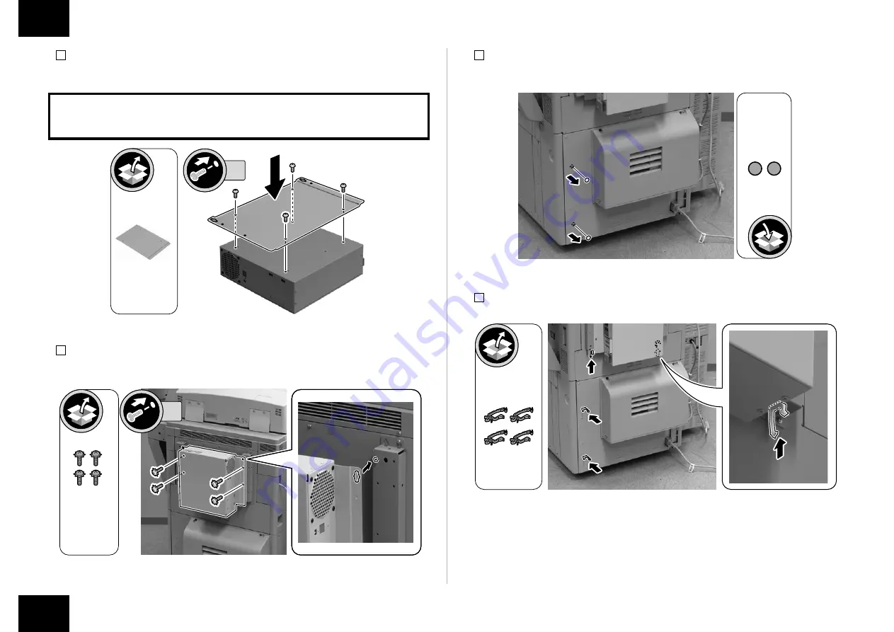
7) Install the PS Unit Fixation Plate.
•  4 Screw (Use the screws removed in steps 6.)

CAUTION:
Be sure to install it in the correction direction.

4x

8) Hook the PS Unit to the 2 Stepped Screws (M4) tightened in step 5, and install it.
•  4 Screws with Toothed Washer (Binding; M4 x 8)

Screw with 

Toothed Washer

Binding; M4x8

4x

F-1-23

F-1-24

9) Remove the 2 Face Seals of the Rear Lower Cover (the removed Face Seals will not be 

used).

10) 

Install the 4 Wire Saddles.

F-1-25

F-1-26

Содержание imagePRESS Server G100

Страница 1: ... English These procedures are different from each other Follow the procedure corresponding to the installed model Japanese The installation procedure for Japan model English The installation procedure for the other models except for Japan model この設置手順書には 和文と英文の設置手順が記載されている 和文では日本モデル用の設置手順が記載されており 英文では日本モデル以外のその他のモデル用の設 置手順が記載されている それぞれの設置手順は異なっているので モデルに応じた手順に従うこと 和文 日本モデル用設置手順 英文 日本モデル以外のその他のモデル用...

Страница 2: ...icate included in the package and obtain the license key in advance Make the setting of the EFI Controller by the Web browser in the Control Panel Register the license by the following procedure 1 Log in to the host machine as an administrator mode Factory default password is as follows System administration division ID 7654321 System administration password 7654321 CAUTION When System Manager Inf...

Страница 3: ...ent shape depending on locations Use the correct power code to match the location area of installation Make sure not to leave unused power code at the site The parts 10 to 12 and 13 to 16 are packed in single bags 10 to 12 To be used when installing the Open I F PCB 13 to 16 To be used when installing the PS Unit F 1 2 Europe X2 USA X 1 1 PS Unit X 1 3 Power Cord X 1 2 PS Unit Fixation Plate X 1 4...

Страница 4: ...he host machine Check that the main power switch is OFF 1 Turn OFF the main power switch of the host machine 2 Be sure that display in the Control Panel and the lamp of the main power supply are turned off then disconnect the power plug Check when Connecting the Power Plug to an Outlet When connecting the power plug of this equipment to an outlet be sure to use an outlet of a system different from...

Страница 5: ... Installing the Open I F PCB Installation Procedure Installing the Open I F PCB 1 Remove the Box Left Cover 4 Screws 4x F 1 6 2 Disconnect the Reader Communication Cable and release the 2 Lock Levers 1x 3 Hold the grip to remove the Main Controller PCB 2 2 Screws 2x F 1 7 F 1 8 ...

Страница 6: ...ace Cover in case it is needed in the future 2x 5 Remove the screw and replace it with the Card Spacer the removed screw will be used in step 8 1x F 1 9 F 1 10 6 Remove the Bypass PCB the removed Bypass PCB will not be used 2 Screws The removed screws will be used in step 8 1 Connector NOTE Ask the user to store the Bypass PCB in case it is needed in the future 2x 1x 7 Install the Open I F PCB Mou...

Страница 7: ...er PCB 2 with both hands until it stops CAUTION Install the Main Controller PCB 2 while paying attention not to trap cables Lock Lever F 1 13 F 1 14 10 Turn over the 2 Lock Levers and push in and secure the Main Controller PCB 2 2 Screws Install in order of bottom and top CAUTION Be sure to perform the work in the order from 1 to 5 in the figure because the connector of the Main Controller PCB 2 m...

Страница 8: ...AUTION When installing the Box Left Cover be careful not to trap cables 4x F 1 17 Installing the PS Unit 1 Remove the 2 Face Seals of the Rear Upper Cover and loosen the 2 Screws the removed Face Seals will not be used 2x 2 Hook the Support Plate to the screw right side loosened in step 1 and install it in the direction of the arrow 1 Screw TP M3 x 6 1x Screw Screw Support Plate TP M3x6 F 1 18 F 1...

Страница 9: ...ll it in the direction of the arrow 1 Screw TP M3 x 6 Screw Screw Support Plate 1x TP M3x6 4 Tighten the 2 screws loosened in step 1 Screw 2x F 1 20 5 Install the 2 Stepped Screws M4 to the Support Plate Support Plate Support Plate Stepped Screw Stepped Screw 2x Stepped Screw M4 6 Remove the 8 screws of the PS Unit the removed screw will be used in step 7 8x F 1 21 F 1 22 ...

Страница 10: ...6 CAUTION Be sure to install it in the correction direction 4x 8 Hook the PS Unit to the 2 Stepped Screws M4 tightened in step 5 and install it 4 Screws with Toothed Washer Binding M4 x 8 Screw with Toothed Washer Binding M4x8 4x F 1 23 F 1 24 9 Remove the 2 Face Seals of the Rear Lower Cover the removed Face Seals will not be used 10 Install the 4 Wire Saddles F 1 25 F 1 26 ...

Страница 11: ...1 Connect the Interface Cable to the PS Unit 2 Wire Saddles 2x 1x 12 Open the HDD Cover connect one end of the Cross Ethernet Cable to the host machine and then connect another end to the PS Unit 1x 1x F 1 27 F 1 28 13 Close the HDD Cover 14 Connect the Shield Ethernet Cable to the PS Unit 1x F 1 29 ...

Страница 12: ...ommended When using the non sealed type UTP cable it may influence the surrounding electronic equipments via network cable 2x 1x F 1 30 17 Connect the power plug to the outlet of the host machine 18 Connect the power plug to the outlet of the PS Unit CAUTION Be sure to use an outlet of a system different from that of the host machine 19 Turn ON the main power switch of the host machine 20 Turn ON ...

Страница 13: ...s in Toolbar ON Hide Address in Toolbar ON The display range of the Web browser is extended F 1 31 F 1 32 Settings after Installation 1 Select Fiery from the main menu on the host machine s LCD 2 Select Login to log in as a system administrator Input of password A password input screen is displayed at the time of installation Entering Fiery 1 in the password field displays the setting screen CAUTI...

Страница 14: ...of server network printer and PDL When making each setting the setting will not be completed unless Save Changes is pressed F 1 35 F 1 36 Example Select Server General 1 2 Check that the items in the General Setup are set and perform Save Changes even if there is no change The setting will not be completed unless Save Changes is pressed F 1 37 F 1 38 ...

Страница 15: ...rox 10 min F 1 39 F 1 40 Checking the Operation After Making the Settings Output Test Page and Configuration by the following procedure and check the connection between the host machine and this equipment as well as the settings of this equipment 1 Select Fiery from the main menu on the host machine s LCD 2 Select Login to log in as a system administrator A password input screen is displayed at th...

Страница 16: ...connect to the network make settings and output the test print Refer to Configuration and Setup in User s Manual for details of checking work Executing image Quality Adjustment Execute the image quality adjustment shown below at installation Refer to Installation in Service Manual for host machine Auto Gradation Adjustment Register Paper to Adjust Execution of Correct Shading Auto Correct Color To...

Страница 17: ... 1x 取付け 電源コード 取外し 目視確認 音確認 確認 OFF 清掃 ON 押下 電源 不要部品 F 1 1 接続前の準備 ライセンスのインストール 同梱されているライセンス証書を取出し 事前にライセンスキーを取得しておく EFI コントロー ラーの設定は 本体の操作部から Web ブラウザで行う 以下の手順でライセンスの登録を行う 1 管理者 モード で本体にログインする 工場出荷時のパスワードは下記である システム管理部門 ID 7654321 システム管理暗証番号 7654321 注意 システム管理者情報の設定 がされている時は ユーザー管理者の指示に従い管 理者としてログインする必要がある 2 設定 登録 管理設定 ライセンス その他 ライセンスの登録 を選択する 3 WEB ブラウザのライセンスキーを入力する 例 8888 7777 6666 5555 4444 3333 4...

Страница 18: ... 以上のスペースが必要である 200 mm以上 背面 本機 前面 同梱部品の確認 メモ 10 12 13 16 はそれぞれ 1 つの袋にまとめて梱包されている 10 12 Open I F PCB 取付け時に使用する 13 16 PS ユニット取付け時に使用する F 1 2 1 PSユニット X 1 3 電源コード X 1 2 PSユニッ ト固定板 X 1 4 クロスイーサネット ケーブル X 1 6 オープンI F基板 X 1 7 支持板 X 2 8 インターフェース ケーブル 1 0 m X 1 10 オープンI F基板 取付け板 X 1 11 カードスペーサー X 1 12 ビス TP M3x6 X 4 5 シールドイーサネット ケーブル 3 0 m X1 9 ライセンス証書 X 1 F 1 3 ...

Страница 19: ...2 14 歯付き座金付ビス バインド M4x8 X 4 16 ビス TP M3x6 X 6 2本使用 CD ガイド類 メディアパック クイックセットアップペラ F 1 4 本体主電源 OFF の確認事項 本体の主電源が OFF であることを確認する 1 本体の主電源スイッチを OFF する 2 操作パネルの表示と主電源ランプが消えたことを確認してから電源プラグを外す 電源接続時の確認 本機の電源プラグをコンセントに差込む場合 本体と別系統のコンセントを使用すること 取付け概略図 F 1 5 ...

Страница 20: ...プン I F 基板の取付け 設置手順 オープン I F 基板の取付け 1 ボックス左カバーを外す ビス 4 本 4x 2 リーダー通信ケーブルを外し ロックレバー 2 箇所を解除する 1x F 1 6 F 1 7 3 取っ手を持ち メインコントローラー基板 2 を外す ビス 2 本 2x 4 目隠し板を外す 外した目隠し板は使用しない ビス 2 本 外したビスは手順 8 で使用する メモ 外した目隠し板はユーザーに渡し 保管して頂くこと 2x F 1 8 F 1 9 ...

Страница 21: ...手順 8 で使用する 1x 6 バイパス基板を外す 外したバイパス基板は使用しない ビス 2 本 外したビスは手順 8 で使用する コネクタ 1 箇所 メモ 外したバイパス基板はユーザーに渡し 保管して頂くこと 2x 1x F 1 10 F 1 11 7 オープン I F 基板取付け板を取付ける ビス TP M3 x 6 1 本 1x TP M3x6 8 オープン I F 基板を取付ける コネクタ 1 箇所 ビス 5 本 手順 4 5 6 で外したビスを使用する ビス TP M3 x 6 3 本 TP M3x6 2x 6x 1x F 1 12 F 1 13 ...

Страница 22: ...ラー基板 2 を突当たるまで両 手で均等に押込む 注意 ケーブル類をはさみこまないように注意して メインコントローラー基板 2 を取付ける ロック レバー F 1 14 10 ロックレバー 2 個を倒して さらにメインコントローラー基板 2 を押込み 固定する ビス 2 本 下 上の順に取付ける 注意 メインコントローラー基板 2 のコネクタが接続されていない場合があるため 図の 1 5 の順番で確実に作業を行うこと 2x 11 リーダー通信ケーブルを取付ける 12 オープン I F 基板にインターフェースケーブルを接続する 1x F 1 15 F 1 16 ...

Страница 23: ...ーフェースケーブルをボックス左カバーの穴に通して ボックス左カバーを取付ける ビス 4 本 注意 ボックス左カバーを取付ける際は ケーブル類を挟まないように注意すること 4x F 1 17 PS ユニットの取付け 1 後上カバーの目隠しシール 2 枚を剥し ビス 2 本を緩める 剥した目隠しシールは使用し ない 2x 2 手順 1 で緩めたビス 右側 に支持板を掛けて 矢印方向に取付ける ビス TP M3 x 6 1 本 1x ビス ビス 支持板 TP M3x6 F 1 18 F 1 19 ...

Страница 24: ... ユニットの取付け 3 手順 1 で緩めたビス 左側 に支持板を掛けて 矢印方向に取付ける ビス TP M3 x 6 1 本 ビス ビス 支持板 1x TP M3x6 4 手順 1 で緩めたビス 2 本を締める ビス 2x F 1 20 F 1 21 5 支持板に段ビス M4 2 本を取付ける 支持板 支持板 段ビス 段ビス 2x 段ビス M4 6 PS ユニットのビス 8 本を外す 外したビス 4 本は手順 7 で使用する 8x F 1 22 F 1 23 ...

Страница 25: ...トの取付け 7 PS ユニット固定板を取付ける ビス 4 本 手順 6 で外したビス 注意 取付ける向きを間違えないこと 4x 8 手順 5 で取付けた段ビス M4 2 本に PS ユニットを掛けて取付ける 歯付き座金付ビス バインド M4 x 8 4 本 歯付き 座金付ビス バインド M4x8 4x F 1 24 F 1 25 9 後下カバーの目隠しシール 2 枚を剥す 剥した目隠しシールは使用しない 10 ワイヤサドル 4 個を取付ける F 1 26 F 1 27 ...

Страница 26: ...26 設置手順 PS ユニットの取付け 設置手順 PS ユニットの取付け 11 PS ユニットにインターフェースケーブルを接続する ワイヤサドル 2 箇所 2x 1x 12 HDD カバーを開き クロスイーサネットケーブルを本体と PS ユニットに接続する 1x 1x F 1 28 F 1 29 13 HDD カバーを閉める 14 シールドイーサネットケーブルを PS ユニットに接続する 1x F 1 30 ...

Страница 27: ...ケーブル の使用を推奨する ノンシールドタイプ UTP ケー ブル を使用すると ネットワークケーブルを経由して 周りの電子機器に影響を及ぼ す可能性がある 2x 1x F 1 31 17 本体の電源プラグをコンセントに差込む 18 PS ユニットの電源プラグをコンセントに差込む 注意 本体と別系統のコンセントを使用すること 19 PS ユニットの電源を ON した後 本体の主電源スイッチを ON する 20 タッチパネル上に 本体の主電源を入れ直してください と表示したら 本体の主電源ス イッチを OFF する 21 再び 本体の主電源スイッチを ON する 22 CNT TYPE の値が 454 であることを確認する サービスモード レベル 1 COPIER OPTION INT FACE CNT TYPE ...

Страница 28: ...項目を ON に設定する 最大表示モードの ON OFF ON ツールバーのボタン部の表示制限 ON ツールバーのアドレス部の表示制限 ON ウェブブラウザーの画面表示が広がる F 1 32 F 1 33 設置後の設定 1 本体の液晶表示部上のメインメニューから Fiery を選択する 2 ログイン を選択し システム管理者としてログインする パスワードの入力 設置時にパスワード入力画面が表示される パスワード欄に Fiery 1 を入力すると設定画面が表示される 注意 Fiery 1 の F は半角大文字で入力する それ以外は半角小文字で入力する F 1 34 F 1 35 ...

Страница 29: ...設定 設置手順 設置後の設定 3 ツール 設定 を選択する 4 サーバー ネットワーク プリンター PDL の設定も確認する 各設定をする場合には 変 更の保存 を行なわないと設定されたことにならない F 1 36 F 1 37 例 サーバー 一般 を選択する 1 2 一般設定内の項目が設定されていることを確認し 変更がなくても 変更の保存 を行う 変 更の保存 を行なわないと設定されたことにならない F 1 38 F 1 39 ...

Страница 30: ...後 設定終了 を押下する 6 確認画面が表示するので 今すぐリブート を選択する 7 PS ユニットが再起動される 約 10 分 F 1 40 F 1 41 設置後の動作確認 以下の手順で テストページ 設定ページを出力し 本体と本機の接続および本機の設定を 確認する 1 本体の液晶表示部上のメインメニューから Fiery を選択する 2 ログイン を選択し システム管理者としてログインする パスワード欄に Fiery 1 を入力すると設定画面が表示される F 1 42 F 1 43 ...

Страница 31: ...整の実施 3 情報 ページの印刷 PS テストページ を選択する 1 2 3 4 はい を押下する F 1 44 F 1 45 ネットワークへの接続 ネットワーク管理者にネットワークへの接続 設定およびテストプリントを依頼する 確認作業 は ユーザーマニュアルの 設定管理 を参照して行う 画質調整の実施 設置時には 以下の画質調整を行う 本体サービスマニュアル参照 自動階調補正 補正用紙登録 濃度ムラ補正 自動色調補正 イメージリーダーユニット設置時のみ ...

Страница 32: ......

Отзывы: