Canon imagePRESS Lite C270 Скачать руководство пользователя страница 603

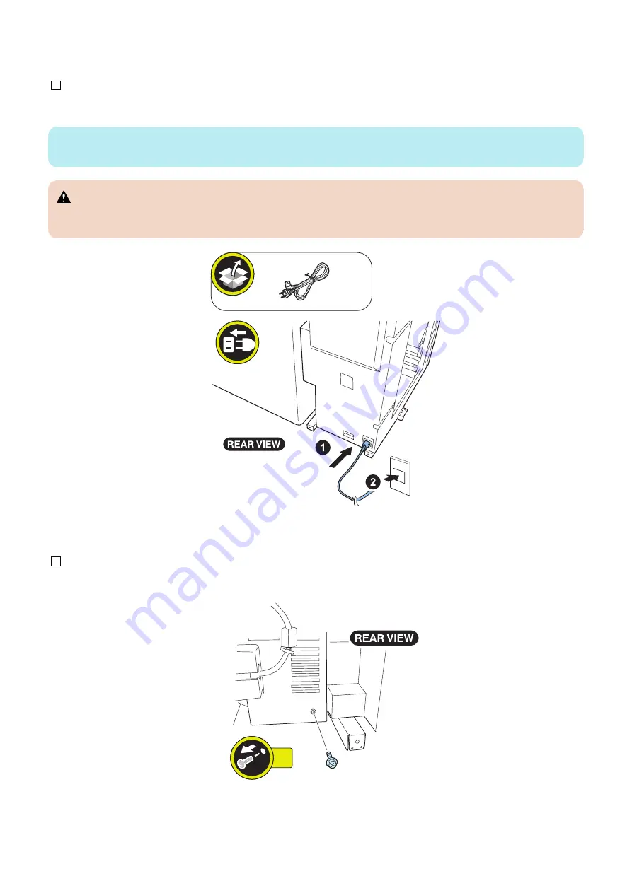
■ Connecting the Power Cord

1. Insert the Power Cord into this equipment. Connect the plug end of the Power Cord into an external power outlet.

NOTE:

Illustrations used in this procedure are those of imagePRESS C10000VP series.

 CAUTION:

Make sure that the Intermadiate power cable connects to the socket firmly. If connecting precariously, it may result in a
smoke or fire.

■ Connecting the Shunt Cable

1. Remove the screw at the rear lower position of the Buffer Pass Unit.

1x

6. Paper Output Options

594

Содержание imagePRESS Lite C270

Страница 1: ...INSTALLATION MANUAL imagePRESS Lite C270 C265 Canon September 7 2022 Rev 4 COPYRIGHT 2022 CANON INC CANON imagePRESS Lite C270 C265 Rev 4 PRINTED IN U S A ...

Страница 2: ...touch Mac OS X and Safari are trademarks of Apple Inc Microsoft Windows Windows Vista Windows Server Internet Explorer Microsoft Edge Excel and PowerPoint are either registered trademarks or trademarks of Microsoft Corporation in the United States and or other countries Google Cloud Print Google Chrome and Android are either registered trademarks or trademarks of Google Inc iHQC compression techno...

Страница 3: ...edure 1x 1x 1x Install Screw Packaged Item Remove Tighten Loosen 1x Connect Connector Disconnect Install Harness Common for Guides and Clamps Remove 1x 1x Connect Power Cord Disconnect Check visually Check the sound Check OFF Cleaning ON Push Power Unused Parts 1x 1x Important Notices ...

Страница 4: ... in the package 13 Symbols 13 Checking before Installation 14 Checking the Power Supply 14 Checking the Installation Environment 14 Points to Note at Installation 14 Points to Note When Moving This Host Machine 14 Checking the installation space 15 Installation Procedure 17 Unpacking 17 Checking the Contents 22 Installing the Scanner 24 Installing the Buffer Path Unit Only Models with the Buffer P...

Страница 5: ...utline Drawing 151 Installation Procedure 151 Operation Check 168 Reader Heater P1 169 Checking the Contents 169 Installation Outline Drawing 169 Installation Procedure 170 4 Host Machine Options 188 Connection Kit A4 for Bluetooth LE 189 Checking the Contents 189 Installation Outline Drawing 189 Installation Procedure 190 Setting after Installation 204 Numeric Keypad A2 205 Points to Note before ...

Страница 6: ...ing 264 Checking the Contents 265 Installation Procedure 266 Checking the Operation 270 Super G3 2nd Line Fax Board AX1 272 Product Name 272 Installation Outline Drawing 273 Checking the Contents 274 Installation Procedure 275 Checking the Operation 280 SSD related Option 282 Pre checks 282 TYPE 1 Option SSD 1TB 282 TYPE 2 Memory Mirroring Kit 290 imagePRESS Server M20 301 The IP addresses for com...

Страница 7: ...king before Installation 407 Unpacking 409 Checking the Contents 416 Installation Procedure 417 Removing from the Connection Equipment 464 Relocating the Machine 473 Paper Deck Path Kit B1 479 Checking before Installation 479 Unpacking 479 Checking the Contents 482 Installation Procedure 484 Checking after Installation 507 Long Sheet Tray B1 508 Points to Note at Installation 508 Checking the Cont...

Страница 8: ...tents 642 Installation Procedure 643 Adjustment 661 Checking after Installation 673 Staple Finisher AG1 Booklet Finisher AG1 675 Checking before Installation 675 Unpacking Procedure 677 Checking the Contents 681 Installation Procedure 682 Adjusting the Height 711 Connecting the LAN Cable 716 Connecting the Power Cord and Operation Check 720 Side Registration Skew Adjustment 721 Peeling and Attachi...

Страница 9: ...ste Full Sensor 818 Checking and Adjusting the Punch Hole Position 819 Finisher Jogger Kit A1 823 Checking Before Installation 823 Unpacking Procedure 823 Checking the Contents 824 Installation Procedure 825 Checking after Installation 833 Inner Booklet Trimmer A1 835 Checking before Installation 835 Checking the Supplied Parts 835 Installation Procedure 836 Operation Check 855 Booklet Trimmer G1 ...

Страница 10: ...Safety Precautions Toner Safety 2 Points to Note at Installation 2 ...

Страница 11: ...dow 3 Be sure to provide adequate ventilation of the room to keep the work environment comfortable Room odor can be bothering when running the machine for a long time in a poorly ventilated room although the ozone amount generated while running this equipment does not harm human health Points to Note Before Servicing At servicing be sure to turn OFF the power source according to the specified step...

Страница 12: ...2 The display in the Control Panel and the lamp of the main power are turned off Points to Note When Turning ON OFF the Main Power The following message is displayed 1 When a message prompting to turn OFF and then ON the main power appears turn OFF and then ON the main power switch 2 If a message prompting the user to update the version appears press Update to automatically update the version of t...

Страница 13: ...the Booklet Finisher X1 Paper Folding Unit J1 Multi Function Professional Puncher B1 Document Insertion Unit N1 Buffer Path Unit M1 Multi drawer Paper Deck C1 are installed 500 mm or more 500 mm or more 2 900 mm or more 4 900 mm or more 2 800 mm or more 500 mm or more NOTE 2 Make sure to provide at least 100 mm of space if none of the Paper Folding Unit J1 Multi Function Professional Puncher B1 Do...

Страница 14: ...r illustrations used for explanationmay differ from the actual things the procedure is the same Description on the parts included in the package The parts with a diagonal line in the contents list will not be used Safety Precautions 5 ...

Страница 15: ...Product Lineup 1 Image Reading System Options 7 Function expansion system options 8 Pickup Delivery System Options 10 ...

Страница 16: ...ess Handle A1 Product name Required options conditions etc Printer Cover H2 on page 150 Cannot be installed with the DADF ADF Access Handle A1 It is the handle to support opening and closing the Feeder Reader Heater P1 on page 169 Option for Reader Unit 1 Product Lineup 7 ...

Страница 17: ...magePRESS Server M20 Serial Interface Kit K3 Copy Control Interface Kit A1 on page 257 Required when the coin manager is connected Using with Copy Card Reader F1 and Serial Interface Kit K3 is not available Serial Interface Kit K3 Copy Control Interface Kit A1 on page 257 Required when the coin manager is connected Using with Copy Card Reader F1 and Copy Control Interface Kit A1 is not available V...

Страница 18: ...x Kit A1 IP FAX Expansion Kit B1 PCL Asian Font Set A1 PCL International Font Set A1 Barcode Printing Kit D1 Graphic Arts Package Premium Web Activate Productivity Package Web Activate Fiery Compose Fiery Impose Fiery JobExpert and PDF Processing KIT Fiery Impose and Compose Picture Login A1 imagePRESS PS Printer Kit G1 Only the USA model is a standard imagePRESS PS Printer Kit H1 Only the CN mode...

Страница 19: ...eder Attachment F1 Cassette Heater Unit 38 Accessory Interface Kit A2 Multi Function Professional Puncher C1 Buffer Pass Unit M1 Document Insertion Unit R1 Paper Folding Unit K1 Paper Deck Unit E1 Paper Deck Heater Unit A1 Copy Tray R2 Stack Bypass Alignment Tray D1 Long Sheet Tray B1 Long Sheet Tray B1 Long Sheet Tray B1 Document Insertion Folding Unit K1 Staple Finisher AC1 Booklet Finisher AC1 ...

Страница 20: ...hen a finisher is connected Using with Document Insertion Unit R1 is not available Buffer Pass Unit M1 on page 556Multi Function Professional Puncher C1 Necessary when a finisher is connected Paper Folding Unit K1 on page 639Paper Folding Unit K1 Necessary when a finisher is connected Buffer Pass Unit M1 on page 556Staple Finisher AG1 Using with Booklet Finisher AG1 is not available Buffer Pass Un...

Страница 21: ...Host Machine 2 How to Utilize This Installation Procedure 13 Checking before Installation 14 Installation Procedure 17 ...

Страница 22: ...bols The frequently performed operations are described with symbols in this procedure 1x 1x 1x Install Screw Packaged Item Remove Tighten Loosen 1x Connect Connector Disconnect Install Harness Common for Guides and Clamps Remove 1x 1x Connect Power Cord Disconnect Check visually Check the sound Check OFF Cleaning ON Push Power Unused Parts 1x 1x 2 Host Machine 13 ...

Страница 23: ...ammonium gas If the area is exposed to direct rays of the sun provide curtains to the window 3 Be sure to provide adequate ventilation of the room to keep the work environment comfortable Room odor can be bothering when running the machine for a long time in a poorly ventilated room although the ozone amount generated while running this equipment does not harm human health Points to Note at Instal...

Страница 24: ...he following options Paper Folding Unit K1 Document Insertion Unit R1 Multi Deck E1 ensure a space of 800 mm or more When attaching with Multi Deck E1 Stack Bypass Alignment Tray D1 Document Insertion Unit R1 Multi Function Professional Puncher C1 Paper Folding Unit K1 Booklet Finisher AG1 Booklet Trimmer G1 Two Knife Booklet Trimmer B1 3 324 mm or more 1 800 mm or more 1 000 mm or more 2 7 952 mm...

Страница 25: ...more 2 NOTE 2 When not installing any of the following options Paper Folding Unit K1 Document Insertion Unit R1 ensure a space of 100 mm or more 3 Install the machine in a well ventilated location In a location with a mixture of multiple host machines be sure to install the machine where the air exhausted from other machines will not directly enter the machine Do not install the machine in the imm...

Страница 26: ...cure more space for the work than shown in the figure below 1 The dimensions of the host machine and transportation container are as shown in the figure below Secure the space for unpacking before work 1 041 mm 1 150 mm 1 465 mm 2 The following space is needed when unloading from the pallet 1 Pallet 2 Slope Plate 3 Host Machine 1 2 3 2750 mm 2 Host Machine 17 ...

Страница 27: ...in the package and then lift down the box from the pallet CAUTION Be careful not to drop the box included in the package when removing the tapes 3 Pull the plastic bag all the way down 4 Hold the handles on the right side of the host machine lift the host machine and remove the pad Put the plastic bag aside in the direction of the arrow beforehand CAUTION Be careful not to lift the host machine to...

Страница 28: ...the balance will be lost Plastic Bag Pad Handle 6 Take out the 2 Slope Plates stored on the right side of the pallet and remove the 2 pins taped to the backside of the Slope Plates 7 After turning the 2 Slope Plates over and installing them as shown in the figure align the pin holes on the pallet with those on the Slope Plates and insert the 2 pins Pin Slope 2 Host Machine 19 ...

Страница 29: ...ope plates Handle Handle 9 Remove tapes on the exterior surface of the host machine 10 Open the DADF and remove the packing materials from the Reader Assembly Remove the fixing member of the DADF and Reader section by the next section Installing the optical system 11 Remove the packaging materials from the Document Pickup Tray 12 Pull out the cassette 3 13 Take out its contents and remove the tape...

Страница 30: ...14 Return the cassette 3 to the original position 15 Remove the tape and fixing member from the cassette 4 2 Host Machine 21 ...

Страница 31: ...2 14 Double sided Tape X 1 15 Wire Saddle X 1 1 Developing Assembly for Color X 3 2 Developing Assembly for Black X 1 3 Drum Unit for Color X 3 4 Noise Reduction Cover X 1 5 UFP Filter X 1 6 Ozone Filter X 1 7 ITB Inner Cover X 1 8 Handle Cover X 6 9 Service Book Holder X 1 10 Screw RS Tightening M4x8 X 2 11 Screw Binding M4x10 X 1 2 Host Machine 22 ...

Страница 32: ...ffers depending on the destination 1 Reader Left Upper Cover X 1 2 Cleaning Cloth X1 3 Paper Size Labels for Deck X 1 4 Paper Size Labels for Deck 5 Copy Prohibition Label 6 Control Panel Language Label X 1 7 Double sided Tape X 1 USA X 1 EUR X 1 USA X 1 EUR X 1 Asia X 2 8 Wire Saddle X 1 9 Rubber Cap X 1 Only for Korea Others Guides are included 2 Host Machine 23 ...

Страница 33: ... Hinge Shaft X 2 9 Screw RS Tightening M4x8 X 9 10 Screw P Tightening M4x10 X 1 11 Wire Saddle X 1 Installing the Scanner NOTE Because the Scanner Fixation Member will be needed when moving the machine be sure to keep it in a safe place When moving the machine be sure to execute following service mode Lv 2 remove the Reader Left Upper and then install the Scanner Fixation Member For details refer ...

Страница 34: ...1 Open the ADF 2 2 Host Machine 25 ...

Страница 35: ...nner Fixation Member rear side NOTE Be sure to keep the Scanner Fixation Member in a safe place for moving the machine NOTE The removed Scanner Fixation Member will be stored in step 8 4 Install the Reader Left Upper Cover 2 Host Machine 26 ...

Страница 36: ...e Scanner Fixation Member front side NOTE Be sure to keep the Scanner Fixation Member in a safe place for moving the machine NOTE The removed Scanner Fixation Member will be stored in step 10 6 Install the Rubber Cap 2 Host Machine 27 ...

Страница 37: ...7 Remove the Maintenance Cover Upper NOTE The removed Scanner Fixation Member will be stored in step 9 8 Remove the strap with a tag from the removed Scanner Fixation Member 2 Host Machine 28 ...

Страница 38: ...9 Store the Scanner Fixation Member 10 Store the Scanner Fixation Member 2 Host Machine 29 ...

Страница 39: ...11 Install the Maintenance Cover Upper 12 2 Host Machine 30 ...

Страница 40: ...13 14 CAUTION If the White Plate is pressed downward it is placed on the Index Sheet so be sure to press it upward 2 Host Machine 31 ...

Страница 41: ...between the White Plate and the Index Sheet Check that the White Plate is not placed on the Index Sheet ADF White Plate Index Sheet Reader Unit White Plate Index Sheet Reader Unit White Plate Index Sheet Reader Unit White Plate Index Sheet Reader Unit ADF ADF ADF 2 Host Machine 32 ...

Страница 42: ...ficiency Unpacking CAUTION Be sure to open the plastic bag before starting the work Holding the Buffer Path Unit without removing the plastic bag may cause slipping Do not hold the area inside the dotted line of the figure otherwise the Paper Path Guide may be deformed Be sure to hold the frame A and the frame B of the Buffer Path Unit Be sure to avoid the harness when holding the frame B otherwis...

Страница 43: ...ard and place the Buffer Path Unit with its bottom side down CAUTION Do not move it using the A part as the fulcrum nor place the unit on the floor while being tilted otherwise the A part may be deformed A 2 Remove the tapes 2 Host Machine 34 ...

Страница 44: ...the Left Lower Cover 1 the removed parts will not be used 2 Screws 2x 2 Install the Cover Support Plate Front and Rear 1 Hook each 1 Protrusion each 2 Screws RS Tightening M4x8 Hook Protrusion 2x RS Tightening M4x8 Front Rear 2 Host Machine 35 ...

Страница 45: ... on the Reverse Door Cover 3 Hooks 1 Screw P Tightening M4x10 P Tightening M4x10 1x Hook Hook CAUTION Before installing the Buffer Path Unit to the host machine check that the Jam Removal Lever is in the location indicated in the figure 2 Host Machine 36 ...

Страница 46: ...unit CAUTION Be careful not to come into contact with the Delivery Outlet Upper Guide A A B Delivery Outlet Upper Guide B 5 Move the Buffer Path Unit in the direction of the arrow and secure it while it is pushed against the Buffer Mounting Plate Front 1 Screw RS Tightening M4x8 1x RS Tightening M4x8 2 Host Machine 37 ...

Страница 47: ...6 Insert the flat blade screwdriver to remove the Connector Cover the removed Connector Cover will not be used 1 Claw 2 Protrusions Claw Protrusion 7 Connect the 3 connectors 3x 2 Host Machine 38 ...

Страница 48: ... Be careful not to trap the cables with the Connecting Harness Cover RS Tightening M4x8 2x 9 Put the Buffer Cable through the groove of the Connecting Harness Cover and install the Connecting Harness Cover to the host machine 2 Protrusions 1 Claw Protrusion Claw 2 Host Machine 39 ...

Страница 49: ...2 Hooks 4 Screws RS Tightening M4x8 NOTE When connecting to the downstream equipment secure the Shunt Cable together at the A part A 4x RS Tightening M4x8 Hook 11 Install a Wire Saddle and secure the Buffer Cable with it 1x 2 Host Machine 40 ...

Страница 50: ...the right side to allow paper feed 13 Align the 2 hinge positions of the Buffer Front Cover with those of the Buffer Path Unit and insert the hinge shafts in the direction of the arrow 14 Close the Buffer Front Cover 2 Host Machine 41 ...

Страница 51: ...the front side loosen the 2 screws A adjust the left and right positions of the Buffer Front Cover and then tighten the screws again A Installing the Fixing Feed Assembly 1 Open the Front Cover 2 Pull out the Fixing Feed Unit and remove the tape 2 Host Machine 42 ...

Страница 52: ...lease the locks and pull the Fixing Feed Unit all the way out again CAUTION Do not release the Lock Springs at both ends of the rail on the rear side to prevent the frame of the Fixing Feed Unit from coming off 4 Open the Inner Delivery Unit 2 Host Machine 43 ...

Страница 53: ...epped Screw Flat Head The removed screw will be used in step 8 1 Screw W Sems The removed screw will be used in step 8 Stepped Screw 2x W Sems 6 Remove the Stepped Screw with the tag The removed screw will not be used 1x 2 Host Machine 44 ...

Страница 54: ... 6 Fixation Members 8 Install the Fixing Upper Cover 1 Stepped Screw the screw removed in step 5 1 Screw W Sems the screw removed in step 5 2x Stepped Screw W Sems 9 Close the Inner Delivery Unit 2 Host Machine 45 ...

Страница 55: ...xing Feed Unit back in the host machine Installing the Process Unit for Color 1 Remove the Process Unit Front Cover 2 Screws NOTE It is designed that the 2 screws do not come off from the cover 2x 2 Host Machine 46 ...

Страница 56: ...ke out the Developing Assembly from the packaging box CAUTION A Developing Assembly for color use is specified with color Be sure that there is no foreign matter metal pieces in particular on your hand when touching the Developing Assembly If any foreign matters attach to the sleeve of the Developing Assembly it may cause image failure Do not tilt or strongly shake the Developing Assembly but be s...

Страница 57: ...es B after the Sleeve Seal When removing the packaging material pay attention not to allow the Sleeve Seal which is to be removed in the next step also to be removed After unpacking do not work with the Supply Mouth facing down to avoid any risk of toner spilling out A B Supply Mouth Packaging Material 6 Slowly remove the Sleeve Seal from the Developing Assembly CAUTION When removing the Sleeve Se...

Страница 58: ...Toner Blocking Sheet Inner inside the Toner Blocking Sheet Outer If it is scattered clean with dry lint free paper Toner Blocking Sheet Inner Toner Blocking Sheet Inner Toner Blocking Sheet Outer 8 Remove 3 tapes B securing the roller B 2 Host Machine 49 ...

Страница 59: ...eve in the reverse direction By rotating it in the reverse direction toner clots on the Sleeve may damage the Toner Blocking Sheet NOTE Toner clots are removed by turning the sleeve in the direction of the arrow 10 Take out the Drum Unit from the packaging box CAUTION A Drum Unit for color use is specified with color 2 Host Machine 50 ...

Страница 60: ...material CAUTION Do not touch the Photosensitive Drum During work do not remove the Protection Sheet from the Drum Unit Packaging Material Protection Sheet 12 Pull the 2 spacers in the direction of the arrow to remove them from the Drum Unit 2 Host Machine 51 ...

Страница 61: ...13 Release the lock of the Fixation Lever of the Drum Unit to lift up the Fixation Lever 14 Remove the Protection Sheet of the Drum Unit 2 Host Machine 52 ...

Страница 62: ... the Developing Assembly and the Drum Unit Turn the Fixation Lever in the direction of the arrow secure the 2 locks and assemble the Process Unit CAUTION When assembling be sure to that the color is correct When assembling be sure to place the Protection Sheet or paper 2 Host Machine 53 ...

Страница 63: ...n the figure are visible If the lock is not completely secure when the Process Unit is introduced into the host machine it may not be possible to remove it from the host machine Groove Lock 16 Secure the harness with the Harness Guides and connect the connector 2x 1x 2 Host Machine 54 ...

Страница 64: ... Unit as shown in the figure and place the left side face of the Process Unit on the guide A of the Process Unit Inner Cover Align the lower right side of the Process Unit with the guide B of the Process Unit Inner Cover and push the unit in horizontally CAUTION When inserting the Process Unit do not touch the Photosensitive Drum at the bottom B A Photosensitive Drum Photosensitive Drum 2 Host Mac...

Страница 65: ...e below shows the positions of the guides A and B A Yellow A Magenta A Cyan B Yellow B Magenta B Cyan While holding the Process Unit with both hands insert about 2 3 of it and then push the handle of the Process Unit with your finger as shown in the figure to insert all the way until it stops 19 Connect the connector 1x 2 Host Machine 56 ...

Страница 66: ... horizontal state otherwise toner scattering or image failure image loss etc may occur 2 Unpack the Developing Assembly for black and remove the packaging material CAUTION Do not remove the tape A of the Supply Mouth until just before installing it in the host machine Do not remove 3 tapes B Because the 3 tapes B secure the roller in place to prevent it from moving when the Sleeve Seal is removed ...

Страница 67: ...seal Otherwise the Toner Blocking Sheet may be caught and damaged by the crease 4 Check that there is no developer scattered on the Toner Blocking Sheet Inner inside the Toner Blocking Sheet Outer If it is scattered clean with dry lint free paper Toner Blocking Sheet Inner Toner Blocking Sheet Inner Toner Blocking Sheet Outer 2 Host Machine 58 ...

Страница 68: ...t in the direction of the arrow CAUTION Do not turn the Developing Sleeve in the reverse direction By rotating it in the reverse direction toner clots on the Sleeve may damage the Toner Blocking Sheet NOTE Toner clots are removed by turning the sleeve in the direction of the arrow 2 Host Machine 59 ...

Страница 69: ...ion 2 Pull out the Developing Assembly Pressure Lever to the front side until it stops and release the pressure 3 Turn the Developing Assembly Pressure Lever in the direction of the arrow Lock Lock Lock 8 Remove the tape A and the packaging material of the Supply Mouth CAUTION Be sure to remove the packaging material of the Supply Mouth A 2 Host Machine 60 ...

Страница 70: ...he assembly in horizontally CAUTION When sliding the Developing Assembly for black inside do not touch the Developing Sleeve Developing Sleeve Rail Rail Slot NOTE While holding the Developing Assembly for black with both hands insert about 2 3 of it and then push the handle of the Black Developing Assembly with your finger as shown in the figure to insert all the way until it stops 2 Host Machine ...

Страница 71: ... Secure the harness with the Harness Guides and connect the connector 1x 1x 11 Turn the Developing Assembly Pressure Lever in the direction of the arrow and push it in to apply pressure 2 Host Machine 62 ...

Страница 72: ... s right and left hooks to the end faces B of the Hinge Shaft Holder on the right and left sides of the host machine B A CAUTION If the Process Unit Inner Cover is pushed to the rear side without keeping the levers horizontal the 2 Stopper Plates A of the hooks run over the inside of the Hinge Shaft Holder B on the right and left sides of the host machine Furthermore if the Process Unit Inner Cove...

Страница 73: ...ocess Unit Inner Cover NOTE The 2 places of the right and left hooks of the Process Unit Inner Cover are hooked to the Hinge Shaft on the right and left sides of the host machine to lock 13 Install the Process Unit Front Cover you removed 2 Screws 2x 2 Host Machine 64 ...

Страница 74: ...over 2 Protrusions 1 Screw Binding M4x10 1x Binding M4x10 15 Align the right and left hinge holes on the Front Upper Cover with the host machine insert the hinge shaft in the direction of the arrow and rotate it and then install the Front Upper Cover 16 Close the Front Upper Cover and Front Cover 2 Host Machine 65 ...

Страница 75: ...stalling the Noise Reduction Cover CAUTION Do not open the Filters until just before installation 1 Remove the Filter Case from the Noise Reduction Cover 1 Claw Claw 2 Open the 2 Filters 2 Host Machine 66 ...

Страница 76: ...3 Install the 2 Filters to the Filter Case CAUTION Be sure that the filter is installed in the correct direction 4 Install the Filter Case to the Noise Reduction Cover 1 Claw Claw 2 Host Machine 67 ...

Страница 77: ...5 Install the Noise Reduction Cover 4 Protrusions 2 Screws RS Tightening M4x8 RS Tightening M4x8 2x 2 Host Machine 68 ...

Страница 78: ...r NOTE If they cannot be rotated by hand use a screwdriver to loosen so they can be rotated by hand 2 Move the adjusters in the direction of the arrow using a screwdriver and secure them NOTE Securing of the adjuster is not for earthquake resistance Preparing Connection of the Main Power 1 Connect the power plug of the host machine to the outlet 2 Host Machine 69 ...

Страница 79: ...Switch if the installation environment is a high humidity environment or a low temperature environment the Drum Heater is turned ON regardless of the Main Power Switch Turn ON the Cassette Heater Switch if the installation environment is a high temperature and high humidity environment Leakage Breaker For the host machine Environment Heater Switch Cassette Heater Switch 2 Host Machine 70 ...

Страница 80: ... equipment NOTE If Skip is selected a message prompting the user to update the version will appear every time the Main machine is started In the service mode Lv 2 shown below it is possible to set not to display the message prompting the user to update the version COPIER OPTION BODY VER CHNG Installing the Toner Container 1 Open the Front Upper Cover only after the toner container replacement scre...

Страница 81: ...g paper type may result in image failure soiled Fixing Assembly or paper wraparound requiring repair by a service technician Refer to Deck Settings on page 82 and Cassette Settings on page 84 for how to set papers Informing the System Administrator That Installation Is Complete When the installation is completed ask the system administrator to change the password Also ask the system administrator ...

Страница 82: ...0 g m2 Top Colour Zero 120 120 g m2 C165 Plain Heavy 1 Hammermill Premium Color Copy 28lb Bond 105 g m2 Top Colour Zero 100 100 g m2 Common Heavy 2 9 Mohawk Navajo Brilliant White 243 g m2 Top Colour Zero 250 250 g m2 Number of sheets to be used 4 sheets or more 1 Place standard type paper to be corrected in the paper source CAUTION Be sure to select the correct paper type weight as the toner and ...

Страница 83: ...sette Settings on page 84 2 Log in as a system manager Factory default password is as follows System administration division ID Administrator System administration password 7654321 CAUTION When System Manager Information Settings is set it is required to log in as a system manager in accordance with instructions from the user administrator NOTE If the mode buttons are displayed be sure to select t...

Страница 84: ...ure to use the largest size of Canon recommended paper or the largest size of paper which the user uses It is preferable to use 320 x 450 mm SRA3 or 330 x 483 mm Do not use special paper color paper coated paper texture paper etc 1 Select Settings Registration Adjustment Maintenance Adjust Image Quality Correct Shading 2 Select the method for correct shading Densitometer Correction Visual Correcti...

Страница 85: ...s of mark numbers from 0 to 8 If all mark numbers from 0 to 8 are shown on the test page make sure to gauge and enter the density values for all imprinted mark numbers If the mark numbers 0 and 8 are not shown on the test page gauge and enter the density values for all the imprinted mark numbers from 1 to 7 and make sure that the density values for the mark numbers 0 and 8 are set to 0 If you ente...

Страница 86: ... density adjustment values 3 Press Fine Adjust for the color that requires adjustment 4 Select the number that requires adjustment enter the density value and press OK 5 Press Output Test Page Start Printing Test page 2 is output 6 View the output test page 2 and confirm that there is no uneven density 7 Press Store and Finish 8 Press OK and exit the Correct Shading screen 9 Execute the Auto Grada...

Страница 87: ...mage Quality Auto Correct Color Tone Settings Register Correction Pattern and press Yes CAUTION It is required that Auto Gradation Adjustment has been executed 3 Select the destination for registration and press Next 4 Select the paper which is used by the user and press Next CAUTION Select the paper used for Auto Gradation Adjustment If paper has been registered for Auto Gradation Adjustment sele...

Страница 88: ...ohibition Label of the appropriate language at the places shown in the figure below USA X 1 EUR X 1 3 Close the DADF Storing the Cleaning Cloth 1 Place the Cleaning Cloth in the space shown in the figure 2 Host Machine 79 ...

Страница 89: ...s Handle Cover 1 Install the Handle Covers 1 Protrusion for each 1 Claw for each In the case of model with Buffer Path Unit 4 Handle Covers In the case of model without Buffer Path Unit 6 Handle Covers 2 Host Machine 80 ...

Страница 90: ...st machine Rear Lower Curtain Sheet CAUTION Be sure to install it after moving the machine to the installation site The host machine can be moved at least back and forth even after it has been installed 1 Move the host machine to the installation site 2 Clean the area to affix the Rear Lower Curtain Sheet with alcohol etc 2 Host Machine 81 ...

Страница 91: ...erent 1 Check that the setting value is 0 in the following service mode COPIER OPTION FNC SW MODEL SZ 2 Check that the setting value is 0 in the following service mode Lv 2 COPIER OPTION FNC SW SENS CNF COPIER OPTION FNC SW MODELSZ2 3 Check that the setting value is 1 in the following service mode Lv 2 COPIER OPTION FNC SW KSIZE SW 4 When having changed the setting turn OFF and then ON the main po...

Страница 92: ... the Left and Right Deck and push in the deck 5 Close the Front Cover 6 Affix Paper Size Labels for Deck according to the paper size Align the Paper Size Label with the edge of the Cassette Number Label and affix it approx 5 mm away from the Cassette Number Label 2 5 mm NOTE If Setup Guide is running skip this procedure 7 Register the type of paper loaded in the paper source 1 Select Settings Regi...

Страница 93: ...you can register it NOTE If Setup Guide is running perform the following works after Setup Guide ends 8 When the size has been changed register the paper size for the Left and Right Deck in the service mode Level 1 Right Deck COPIER OPTION CST P SZ C1 Left Deck COPIER OPTION CST P SZ C2 9 Exit service mode Cassette Settings 1 Pull out the cassette towards the front 2 Loosen the 2 Fixation Screws a...

Страница 94: ...sure to re adjust the positions of the Guide Plates even when setting a new stack of paper of the same size after the cassette has become empty or adding more paper of the same size Do not hold the Guide Plates when tightening the Fixation Screws It could cause paper jams 2x 4 Push in the cassette 5 Perform steps 1 to 4 for the other cassette in the same way NOTE The paper size settings are recogn...

Страница 95: ...ation where the paper is loaded and then press Set 3 Select the paper type same as that of the loaded paper and press OK OK NOTE If the corresponding paper type is not displayed on the simple settings screen press Detailed Settings and make a selection on the Detailed Settings screen If the type of loaded paper is not displayed on the detailed settings screen you can register it Image Position Adj...

Страница 96: ...formance is more likely to occur with them Adjustment Flow NOTE Following adjustments can be semi automatically adjusted by using the Scanner Semi automatic adjustment You can make adjustments at a time by reading a test page by the reader using a guide sheet CAUTION Execute the Left Edge Margin Adjustment 1st side and mechanical adjustments such as the Registration Alignment on Mechanical Adjustm...

Страница 97: ...al Scanning MagnificationRatio Adjustment Vertical Scanning Magnification Ratio Adjustment Leading Edge Margin Adjustment 1st side Left Edge Margin Adjustment 2nd side Software Adjustment END Write down on the Service Label Standard Values L4 Ly Lx Lx2 Lx1 L3 L1 L2 L5 Mechanical Adjustment Adjustment Items Standard Values Paper Source Paper Size Left Edge Margin 1st side L4 2 5 1 5 mm 1 2 User req...

Страница 98: ...e Margin 1st side REGIST L3 4 0 0 8 mm Left Edge Margin 2nd side ADJ REFE L4 2nd side L4 1st side 0 6 mm Adjustment Procedure CAUTION The test print used for adjustment must be magenta halftone image In the case of 2 sided output the first side is printed on the lower side and the second side is printed on the upper side In the case of halftone images delivered face down the leading edge of the fo...

Страница 99: ...djustment proceed to Leading Edge Margin Adjustment 1st side on page 128 When the Scanner is not used Manual adjustment Proceed to When the Scanner is not used Manual adjustment on page 121 Left Edge Margin Adjustment 1st sidet CAUTION Perform the mechanical adjustment for the left edge margin adjustment 1st side but do not adjust by service mode Adjustment of the Right Deck 1 Measure the left mar...

Страница 100: ...3 Pull out the Right Deck 4 Raise the handle and check the position of the scale marked above the screws Loosen the 2 screws of the Hook Support Plate 2x 2 Host Machine 91 ...

Страница 101: ...too large Moving the Hook Support Plate toward the rear makes L4 smaller L4 Ly When L4 is too small Moving the Hook Support Plate toward the front makes L4 larger L4 Ly Ly is fixed 6 Tighten the 2 screws you loosened 7 Close the Right Deck 8 Output a test print from the Right Deck and check that the value is within the specified range 2 Host Machine 92 ...

Страница 102: ...djust the position of the Right Deck Cover using the scale as reference 2 Tighten the 5 screws you loosened 2x 1x 2x Adjustment of the Left Deck 1 Measure the left margin of the image Check that the measured value is within the specified range shown below When the result is out of the specified range perform adjustment by following the following procedure Standard Values L4 2 5 1 5 mm L4 2 Host Ma...

Страница 103: ...is installed perform steps 2 and 3 2 Free the Buffer Cable from the Wire Saddle 1x 3 Remove the Buffer Left Lower Cover 4 Screws 2 Hooks Hook 4x 4 Remove the Handle Cover 1 Claw 1 Protrusion 5 Pull out the Left Deck 2 Host Machine 94 ...

Страница 104: ...6 Raise the handle and check the position of the scale marked below the screws Loosen the 2 screws of the Hook Support Plate 2x 2 Host Machine 95 ...

Страница 105: ... makes L4 smaller L4 Ly When L4 is too small Moving the Hook Support Plate toward the front makes L4 larger L4 Ly Ly is fixed 8 Tighten the loosened 2 screws 9 Close the Left Deck 10 Output a test print from the Left Deck and check that the value is within the specified range 11 Install the Handle Cover 12 Install the Buffer Left Lower Cover 4 screws When the Buffer Path Unit is installed 2 Host M...

Страница 106: ...n the 5 screws and adjust the position of the Left Deck Cover using the scale as reference 2 Tighten the 5 screws you loosened 4x 1x Adjustment of the Cassettes 3 and 4 1 Measure the left margin of the image Check that the measured value is within the specified range shown below When the result is out of the specified range perform adjustment by following the following procedure Standard Values L4...

Страница 107: ...3 Check the position of the scale of the Cassette Lock Unit Loosen the 2 screws of the Cassette Lock Unit 2x 2 Host Machine 98 ...

Страница 108: ...ssette too much otherwise it may not be able to be installed in the host machine NOTE When L4 is too large Moving the Hook Support Plate toward the rear makes L4 smaller L4 Ly When L4 is too small Moving the Hook Support Plate toward the front makes L4 larger L4 Ly Ly is fixed 5 Tighten the loosened 2 screws 6 Return the cassette to the original position 2 Host Machine 99 ...

Страница 109: ...l in Check on page 105 Adjustment of the Multi purpose Tray without Stack Bypass Alignment Tray 1 Measure the left margin of the image Check that the measured value is within the specified range shown below When the result is out of the specified range perform adjustment by following the following procedure Standard Values L4 2 5 1 5 mm L4 2 Open the Multi purpose Tray 2 Host Machine 100 ...

Страница 110: ...4 is too large Moving the tray toward the rear makes L4 smaller L4 Ly When L4 is too small Moving the tray toward the front makes L4 larger L4 Ly Ly is fixed 4 Tighten the 1 screw you loosened 5 Output a test print from the Multi purpose Tray and check that the value is within the specified range 2 Host Machine 101 ...

Страница 111: ...ow When the result is out of the specified range perform adjustment by following the following procedure Standard Values L4 2 5 1 0 mm L4 2 Remove paper from the Multi purpose Tray Auxiliary Tray 3 Loosen the 4 Fixation Screws of the Multi purpose Tray Auxiliary Tray 4x 4 Shift the Paper Guide on the rear side to loosen the 1 screw on the Multi purpose Tray 1x 2 Host Machine 102 ...

Страница 112: ...e as reference 1 scale mark 1 0 mm NOTE When L4 is too large Moving the Hook Support Plate toward the rear makes L4 smaller L4 Ly When L4 is too small Moving the Hook Support Plate toward the front makes L4 larger L4 Ly Ly is fixed 2 Host Machine 103 ...

Страница 113: ...6 Tighten the loosened screw and return the Paper Guide to its original position 1x 7 Place paper on the Multi purpose Tray and adjust the Slide Guides 2 Host Machine 104 ...

Страница 114: ...urpose Tray and check that the value is within the specified range Cassette Pull in Check 1 If the Buffer Path Unit is installed open the Buffer Front Cover 2 Pull out the cassette 200 mm or more CAUTION The pull in mechanism is activated by opening the cassette 200 mm or more 200 mm 2 Host Machine 105 ...

Страница 115: ...and the gap B between the Cassette Front Cover and other external covers are within the appropriate ranges when viewed from the left side Adjustment is not necessary The level difference A between the cassette and other covers the Front Cover and other Cassette Front Covers on the front side should be 2 mm or less The gap B from the cover on the rear side should be 4 to 5 mm A B 2 Host Machine 106...

Страница 116: ...ing the cassette in this situation a gap B is generated between the cassette and the cover on the rear side Measure and write down the gap B B Perform Adjusting the Cassette Front Cover on page 108 and then perform Adjusting the Pull in Guide on page 108 as needed Latch Not Locking The cassette has not been pulled in enough The cassette is not latched and comes out Perform Adjusting the Pull in Gu...

Страница 117: ...n the appropriate range NOTE The appropriate range of the gap is normally 4 to 5 mm but if the cover does not close properly adjust the gap to 5 mm in case the cover is halfway closed 2x 3 Tighten the 2 adjustment screws you loosened 4 Check the level difference again If the difference is still out of the appropriate range perform Adjusting the Pull in Guide on page 108 Adjusting the Pull in Guide...

Страница 118: ...2 Loosen the screw until the stopper touches the front side 1x 3 Pull out the right side A of the cassette while lifting the front side move it to the right and remove the Cassette A 2 Host Machine 109 ...

Страница 119: ...enter In the case of a semi closed cassette Move the Pull in Guide for 1 division of the scale upward toward the rear side A of the host machine so that the amount the cassette is pulled in is reduced In the case of latch not locking Move the Pull in Guide for 1 division of the scale downward toward the front side B of the host machine so that the amount the cassette is pulled in is increased 3x A...

Страница 120: ... Cassette by aligning the triangle mark of the rail on the left side with the triangle mark of the cassette and putting the roller B of the cassette in the A part of the rail on the right side A B 2 Host Machine 111 ...

Страница 121: ...ew Adjustment Mechanical Adjustment for Registration Alignment 1 Obtain the value of skew on the image leading edge Check that the measured value is within the specified range shown below When the result is out of the specified range perform adjustment by following the following procedure Standard Values L1 L2 0 6 mm L1 L2 2 Host Machine 112 ...

Страница 122: ...Lock Springs at both ends of the rail to release the locks and pull the Fixing Feed Unit all the way out again CAUTION Do not release the Lock Springs at both ends of the rail on the rear side to prevent the frame of the Fixing Feed Unit from coming off 2 Host Machine 113 ...

Страница 123: ...4 Remove the Fixing Feed Right Upper Inner Cover 1 Screw 2 Hooks 1x 5 Loosen the 4 screws 2x 2x 2 Host Machine 114 ...

Страница 124: ...just the Registration Adjustment Shaft by turning it with a screwdriver If the value of L1 L2 is turn to the side If the value of L1 L2 is turn to the side 1 scale mark of the dial 0 1 mm 2 Host Machine 115 ...

Страница 125: ...and L2 larger L3 L1 L2 When L1 is smaller than L2 Turning to the side makes L1 larger and L2 smaller L3 L1 L2 L3 is fixed Example In case of L1 L2 0 7 turn the shaft to direction by 7 scales In case of L1 L2 0 5 turn the shaft to direction by 5 scales 2 Host Machine 116 ...

Страница 126: ...that the value is within the specified range NOTE After completing mechanical adjustments proceed to following steps When the Scanner is used Semi automatic adjustment Proceed to When the Scanner is used Semi automatic Adjustment on page 118 After performing the Semi automatic Adjustment proceed to Leading Edge Margin Adjustment 1st side on page 128 When the Scanner is not used Manual adjustment P...

Страница 127: ...e skew adjustment Leading edge right angle adjustment Trapezoid adjustment When the scanner is used be sure to make adjustments by reading a test page by the reader using a guide sheet Guide sheet 1 2 3 4 Test page 2 sided Yellow Green Blue Red Front side Back side How to output a Guide Sheet CAUTION Be sure to clean the Copyboard Glass and the back side of the feeder before adjustment Print the g...

Страница 128: ...System Manager Information Settings is set it is required to log in as a system manager in accordance with instructions of the user administrator 1 Select Settings Registration Preferences Paper Settings Paper Type Management Settings 2 Select paper to use for adjustment press Duplicate and then name for adjustment and save the paper Press OK 3 Make settings of the duplicated paper for adjustment ...

Страница 129: ...reen scan the test page by setting the yellow green and red triangle marks for the second third and fourth scanning respectively CAUTION Do not change the paper settings scanned in Paper Settings or the scan results will be overwritten If settings of another paper have been configured before adjusting the image position start from step 8 to scan the test page again 12 Enter service mode SITUATION ...

Страница 130: ...er have been configured before checking the standard value scan the test page again 16 Enter service mode SITUATION Installation Image position adjustment When use the Scanner 17 Check again that the value displayed in the scan result with M at the end meets the standard Scan Result Standard Values REGIST1M 8 or less DIF REFE 6 or less MAG H 1M 20 or less MAG V 1M 20 or less SLP 1M 6 or less ANGLE...

Страница 131: ...service mode COPIER ADJUST IMG REG SLP 1 Setting range 10 to 10 0 1 mm per increment NOTE When L1 is smaller than L2 When the value is increased L1 becomes larger and L2 becomes smaller L3 L1 L2 When L1 is larger than L2 When the value is decreased L1 becomes smaller and L2 becomes larger L3 L1 L2 L3 is fixed Example When L1 2 5 and L2 1 8 enter 7 because 2 5 1 8 0 7 3 Output a test print from the...

Страница 132: ...L5 x 280 400 0 6 mm L4 L5 2 Adjust the value of the following service mode COPIER ADJUST IMG REG ANGLE 1 Setting range 10 to 10 0 1 mm per increment NOTE When L4 is smaller than L5 When the value is increased L5 becomes smaller L4 L5 When L4 is larger than L5 When the value is decreased L5 becomes larger L4 L5 L4 is fixed Example When L4 2 5 and L5 1 8 enter 7 because 2 5 1 8 0 7 3 Output a test p...

Страница 133: ...T IMG REG TRPZ 1 Setting range 10 to 10 0 1 mm per increment NOTE When Lx1 is smaller than Lx2 When the value is increased Lx1 becomes larger and Lx2 becomes smaller Lx Lx2 Lx1 When Lx1 is larger than Lx2 When the value is decreased Lx1 becomes smaller and Lx2 becomes larger Lx Lx2 Lx1 Lx is fixed Example When Lx1 412 and Lx2 411 4 enter 6 because 412 411 4 0 6 3 Output a test print from the Casse...

Страница 134: ...eck that the measured value is within the specified range shown below When the result is out of the specified range perform adjustment by following the following procedure A3 Ly 292 0 6 mm 11x17 Ly 274 4 0 5 mm Ly 2 Measure the horizontal scanning magnification ratio A3 Ly 292 1 x 100 11x17 Ly 274 4 1 x 100 2 Host Machine 125 ...

Страница 135: ...value When the value is decreased by 1 the horizontal scanning magnification ratio is decreased by 0 01 L4 Ly L4 is fixed Example in the case of A3 paper When Ly 291 291 292 1 x 100 0 342 The value is rounded off to two decimal places When the actually measured value is smaller than the nominal value 292 mm the value of the ratio becomes negative therefore the value to enter is 34 4 Output a test ...

Страница 136: ...the measured value is within the specified range shown below When the result is out of the specified range perform adjustment by following the following procedure A3 Lx 412 0 8 mm 11x17 Lx 423 8 0 8 mm Lx 2 Calculate the vertical scanning magnification ratio of the image A3 Lx 412 1 x 100 11x17 Lx 423 8 1 x 100 2 Host Machine 127 ...

Страница 137: ...aper When Lx 414 414 415 1 x 100 0 240 The value is rounded off to two decimal places When the actually measured value is smaller than the nominal value 415 mm the value of the ratio becomes negative therefore the value to enter is 24 4 Output a test print from the Cassette 3 and check that the value is within the specified range 5 Write down the new adjustment value in the service label Leading E...

Страница 138: ... 1 1 9 3 Output a test print from the Cassette 3 and check that the value is within the specified range 4 Write down the new adjustment value in the service label Left Edge Margin Adjustment 2nd side 1 Obtain the value of left edge margin of image 2nd side Check that the obtained value is within the specified range shown below When the result is out of the specified range perform adjustment by fol...

Страница 139: ...ck that the value is within the specified range 4 Write down the new adjustment value in the service label Image Position Adjustment Single Pass ADF Checking the Skew Check the image at ADF stream reading with using the Test Charts for Image Position Adjustment If any adjustments have been made perform all of the following Adjustment Procedure If it is confirmed that there is no problem proceed to...

Страница 140: ...rrected image Amount of Change per 0 01 degree FEEDER ADJUST ADJ PAR1 front side FEEDER ADJUST ADJ PAR2 back side Refer to the following Service Manual Adjustment Original Feed System Single Pass ADF Skew Adjustment at Stream Scanning of Originals Creating the Test Charts for Image Position Adjustment CAUTION Create the test charts for image position adjustment after completing adjustments on the ...

Страница 141: ... Adjustment of the White Plate 1 2 Host Machine 132 ...

Страница 142: ...2 3 CAUTION If the White Plate is pressed downward it is placed on the Index Sheet so be sure to press it upward 2 Host Machine 133 ...

Страница 143: ...the White Plate and the Index Sheet Check that the White Plate is not placed on the Index Sheet ADF White Plate Index Sheet Reader Unit White Plate Index Sheet Reader Unit White Plate Index Sheet Reader Unit White Plate Index Sheet Reader Unit ADF ADF ADF 2 Host Machine 134 ...

Страница 144: ...ze or LTR paper size Use plain paper 1 to 3 64 to 105 g m2 Paper Type Height Adjustment Checking the Height 1 Check that the 2 Height Adjustment Bosses at the left front side and the left rear side are in contact with the Stream Reading Glass 2 If they are not in contact perform the height adjustment If it cannot be visually checked perform Checking the Height of the Height Adjustment Boss 2 Host ...

Страница 145: ... Height Adjustment Boss 1 Put a sheet of paper on the place where the protrusions touch the Stream Reading Glass and check whether there is any resistance of the paper when closing the ADF The Left Front Side 2 Host Machine 136 ...

Страница 146: ... The Left Rear Side 2 If there is no resistance perform the height adjustment 2 Host Machine 137 ...

Страница 147: ...s not installed properly Turn the Left Hinge Fixation Screw counterclockwise white arrow 2 Open th ADF fully and close the ADF and then Check the height again and see if it is at an appropriate height Light intensity adjustment NOTE This mode automatically performs adjustment If NG is displayed after executing this mode check that PCB and each connector are properly connected 1 Execute the followi...

Страница 148: ...nd close the ADF CAUTION When executing the white level adjustment using paper with smaller width adjustment may not be executed properly 2 Execute the service mode item COPIER FUNCTION CCD DF WLVL1 3 Remove the blank paper from the Copyboard Glass and place it on the Document Pickup Tray of ADF 4 Execute the service mode item COPIER FUNCTION CCD DF WLVL2 5 Place the blank paper on the Copyboard G...

Страница 149: ...accuracy is guaranteed 3 Set the document tray so that the black painted portion becomes the leading edge in the feeding direction 4 Automatic Front Back Side Difference Correction Adjustment is performed in the following service mode FEEDER FUNCTION ADJ SKW NOTE If NG is displayed after executing this mode execute Right Angle Adjustment Slant Adjustment on the service manual 5 Write the adjusted ...

Страница 150: ... to execute Ping can check whether connection to the network is enabled or not Remote host address IP address of PC terminal connected running on TCP IP network environment that connects to this equipment 1 Inform the system administrator about checking of the network connection using Ping 2 Confirm the remote host address with the system administrator 3 Enter the remote host address to Ping The n...

Страница 151: ...ddress 1 Select the following Settings Registration Preferences Network TCP IP Settings IPv4 settings Ping Command and enter the IP address 127 0 0 1 with the numeric keypad and enter Execute key The network function of the Main Controller is working properly if the message say Response from the host If the message say No response from the host the network function of the Main Controller is faulty...

Страница 152: ...2 3 2 Host Machine 143 ...

Страница 153: ... sure to change the number of cushions according to the thickness of the Card Reader If it makes the Control Panel Upper Right Cover difficult to install using one or no cushions is allowed 5 2 Host Machine 144 ...

Страница 154: ...e surface with alcohol after removing the sheet If any glue remains in the peeled Surface remove it with the peeled sheet 7 NOTE Store the excess length of the cable in the position as shown in the figure 1x 1x 2 Host Machine 145 ...

Страница 155: ... When installing with the Numeric Keypad at the same time NOTE Store the excess length of the cable in the position as shown in the figure 1x 8 2 Host Machine 146 ...

Страница 156: ...9 10 11 2 Host Machine 147 ...

Страница 157: ...12 Connect the power plug to the outlet 13 Turn ON the main power switch 2 Host Machine 148 ...

Страница 158: ...Image Reading System Options 3 Printer Cover H2 150 Reader Heater P1 169 ...

Страница 159: ...ion go back to the state where copying can be performed again and perform automatic gradation correction full correction and then perform the procedure for attaching to the printer cover Set 0 for the following service mode COPIER OPTION FNC SW W SCNR COPIER FUNCTION INSTALL FAX USE Exit service mode Turn OFF the main power switch Confirm that the operation panel is displayed and the POWER lamp is...

Страница 160: ...Installation Outline Drawing Installation Procedure Removing the Covers 1 6x 3 Image Reading System Options 151 ...

Страница 161: ...2 2x 3 4 1x 3 Image Reading System Options 152 ...

Страница 162: ...5 3x 3 Image Reading System Options 153 ...

Страница 163: ... Removing the ADF 1 1x 2x 3 Image Reading System Options 154 ...

Страница 164: ...2 1x NOTE Removed parts will be used in step of Installing the Printer Cover 3 3 Image Reading System Options 155 ...

Страница 165: ...NOTE When performing following procedures using ADF in the book mode as necessary makes the work easy The book mode is released by opening the ADF 4 3 Image Reading System Options 156 ...

Страница 166: ...5 3x 6 3 Image Reading System Options 157 ...

Страница 167: ...7 CAUTION Be careful not to drop the ADF 4x 3 Image Reading System Options 158 ...

Страница 168: ... Removing the Reader Unit 1 3x 2 2x 2x 3 Image Reading System Options 159 ...

Страница 169: ...3 3x 4 4x 3 Image Reading System Options 160 ...

Страница 170: ...5 3x NOTE Removed 2 screws will be used in step of Installing the Printer Cover 6 3 Image Reading System Options 161 ...

Страница 171: ... Installing the Printer Cover 1 NOTE In order to make it easy to install the Reader Fixation Plate R untie the two parts shown in the figure and loosen the cable 2x 3 Image Reading System Options 162 ...

Страница 172: ...Printer Cover with nippers by using the edge part B as a guide Be sure not to make burrs B A 3 CAUTION When placing the Printer Cover be careful not to trap cables on the rear side of the host machine 3 Image Reading System Options 163 ...

Страница 173: ...g screws removed in step of Removing the Reader Unit CAUTION Be careful not to trap cables on the right side of the host machine at installation 3x 3x P Tightening M4x10 Binding Binding 3 Image Reading System Options 164 ...

Страница 174: ...5 CAUTION Be careful not to trap cables on the right side of the host machine at installation 3x 3x RS Tightening M4x8 P Tightening M4x10 3 Image Reading System Options 165 ...

Страница 175: ...6 NOTE Use parts removed in step of Removing the ADF CAUTION Be careful not to trap cables on the rear side of the host machine at installation 1x 7 2x 3 Image Reading System Options 166 ...

Страница 176: ... Installing the Covers 1 3x 2 1x 3 2x 3 Image Reading System Options 167 ...

Страница 177: ...fter turning ON the main power switch turn OFF and then ON the main power switch and then perform the following steps 3 The message confirming the cable connection of the Reader Unit is displayed 4 Set 0 for the following service mode COPIER OPTION FNC SW W SCNR COPIER FUNCTION INSTALL FAX USE 5 Exit service mode 6 Turn OFF and then ON the main power switch 3 Image Reading System Options 168 ...

Страница 178: ...Reader Heater P1 Checking the Contents 1x 1x 1x 2x 4x 2x Binding M4x4 2x Large 2x Large 3x Small 5x Small 1x Middle 1x Installation Outline Drawing 3 Image Reading System Options 169 ...

Страница 179: ...Installation Procedure Removing the Covers 1 6x Installing the Reader Heater 1 3 Image Reading System Options 170 ...

Страница 180: ...e and the White Plate affects reading When removing or installing the Copyboard Glass be sure not to touch the glass surface and the White Plate If soiling is attached clean it with lint free paper White Plate 3 Image Reading System Options 171 ...

Страница 181: ...4 1x NOTE When performing following procedures using ADF in the book mode as necessary makes the work easy The book mode is released by opening the ADF 3 Image Reading System Options 172 ...

Страница 182: ...5 6 3x 1x 3 Image Reading System Options 173 ...

Страница 183: ...7 1x 8 3x 3 Image Reading System Options 174 ...

Страница 184: ...9 10 11 2x 3 Image Reading System Options 175 ...

Страница 185: ...12 13 Middle 3 Image Reading System Options 176 ...

Страница 186: ...14 15 2x Binding M4x4 3 Image Reading System Options 177 ...

Страница 187: ...16 Small 17 1x 3 Image Reading System Options 178 ...

Страница 188: ...18 7x 19 2x 3 Image Reading System Options 179 ...

Страница 189: ...20 21 3x 1x 3 Image Reading System Options 180 ...

Страница 190: ...22 CAUTION Be sure to hold down the Reader Heater Harness because it may interfere with moving of the Scanner Box if it is not connected properly 3x 3 Image Reading System Options 181 ...

Страница 191: ...23 CAUTION Be sure to hold down the Reader Heater Harness because it may interfere with moving of the Scanner Box if it is not connected properly 2x 1x 24 3 Image Reading System Options 182 ...

Страница 192: ...AUTION Move the Scanner Box to the right edge and check if the underside of the Scanner Box and the HP Sensor Flag Plate do not interfere with the Reader Heater harness 3 Image Reading System Options 183 ...

Страница 193: ...25 26 3x 3 Image Reading System Options 184 ...

Страница 194: ...27 1x 1x 28 29 1x 3 Image Reading System Options 185 ...

Страница 195: ... the White Plate affects reading When removing or installing the Copyboard Glass be sure not to touch the glass surface and the White Plate If soiling is attached clean it with lint free paper White Plate 31 2x 3 Image Reading System Options 186 ...

Страница 196: ...32 Installing the Covers 1 6x 2 Turn ON the Environment Heater Switch 3 Connect the power plug to the outlet 4 Turn ON the main power switch 3 Image Reading System Options 187 ...

Страница 197: ...opy Card Reader F1 Copy Card Reader Attachment A5 222 Voice Guidance Kit G1 235 Voice Operation Kit D1 246 Serial Interface Kit K3 Copy Control Interface Kit A1 257 Super G3 FAX Board AX1 264 Super G3 2nd Line Fax Board AX1 272 SSD related Option 282 imagePRESS Server M20 301 Accessory Interface Kit A2 317 ...

Страница 198: ... NOTE mark item may not be included 17 9 mm 33 9 mm D TP M3x6 1x P Tightening M3x8 2x W Sems M3x6 1x 1x B for CN KR 1x for US 1x for TW 1x A 1x 1x 1x 1x G F 1x E 1x 1x 1x H 1x I 1x 1x J 4x 1x C 1x 1x 1x Installation Outline Drawing 4 Host Machine Options 189 ...

Страница 199: ...Installation Procedure 1 2 4 Host Machine Options 190 ...

Страница 200: ...3 4 5x 4 Host Machine Options 191 ...

Страница 201: ...5 CAUTION Do not pull the Control Panel too much to the front If so the Control Panel comes off and gives stress to the cable 6 6x 4 Host Machine Options 192 ...

Страница 202: ...7 3x 8 2x 9 4 Host Machine Options 193 ...

Страница 203: ...10 1x 11 CAUTION Connect the part number label side of the USB cable due to the possibility of wire bite TP M3x6 1x 1x 4 Host Machine Options 194 ...

Страница 204: ...12 7x 13 NOTE Remove the three cables from the reuse band that is holding the cables and cut and remove the reuse band 2x 4 Host Machine Options 195 ...

Страница 205: ...ion of a 10 mm wide white tape due to a risk of getting the wire harness bitten NOTE Secure the removed cables and the USB cable with the included new reuse band Fix the cable with a reuse band to prevent any slack 2x CAUTION 4 Host Machine Options 196 ...

Страница 206: ...15 NOTE Remove the three cables and the one cable from the reuse band that is holding the cables and cut and remove the reuse band 2x 4 Host Machine Options 197 ...

Страница 207: ...osition of a 10 mm wide white tape due to a risk of getting the wire harness bitten NOTE Secure the removed cables and the USB cable with the included new reuse band Fix the cable with a reuse band to prevent any slack 2x 4 Host Machine Options 198 ...

Страница 208: ...17 1x 1x 12x 18 3x 4 Host Machine Options 199 ...

Страница 209: ...19 1x 20 2x 21 4 Host Machine Options 200 ...

Страница 210: ...22 6x 23 5x 24 4 Host Machine Options 201 ...

Страница 211: ...25 26 4 Host Machine Options 202 ...

Страница 212: ...27 4 Host Machine Options 203 ...

Страница 213: ... in as a system manager in accordance with instructions of the user administrator 4 Select Settings Registration Preferences Network Confirm Network Connection Setting Changes and set the item ON 5 Select Settings Registration Preferences Network Bluetooth Settings Use Bluetooth ON 6 The message Perform Apply Setting Changes from Settings Registration appears in the Touch Panel Display 7 Perform A...

Страница 214: ...ic Keypad first The pictures and illustrations used may be different from the product in front of you but the procedure is the same Checking the Contents 1x 1x 2x 1x 1x 1x TP M3x6 2x TP M3x10 3x 1x P Tightening M3x8 2x Large 1x Small 1x Binding M4x16 3x TP M3x16 3x Binding Tapping M3x16 3x 2x Large 1x Installation Outline Drawing 4 Host Machine Options 205 ...

Страница 215: ...Installation Procedure 1 2 4 Host Machine Options 206 ...

Страница 216: ...3 4 5 4 Host Machine Options 207 ...

Страница 217: ...sure to check that the 2 bosses are fitted securely Installing the Control Panel Right Upper Cover while the bosses are not fitted securely will cause rattling 2x P Tightening M3x8 7 Small 4 Host Machine Options 208 ...

Страница 218: ...first core along with the white tape affixed to the Numeric Keypad cable Fold the cable as shown in the figure and attach the second core in a line symmetric position with respect to the core attached first 4 Host Machine Options 209 ...

Страница 219: ...10 3x 1x 11 Large 4 Host Machine Options 210 ...

Страница 220: ...12 1x 1x 4 Host Machine Options 211 ...

Страница 221: ...TE Store the excess length of the cable in the position as shown in the figure When installing with the IC Card Reader at the same time NOTE Store the excess length of the cable in the position as shown in the figure 1x 4 Host Machine Options 212 ...

Страница 222: ...14 TP M3x6 1x 15 CAUTION Place the Core in the position as shown in the figure 4 Host Machine Options 213 ...

Страница 223: ...16 17 Connect the power plug to the outlet 18 Turn ON the main power switch 4 Host Machine Options 214 ...

Страница 224: ...ing to Combination Table of Accessory Installation on page 9 Checking the Contents The parts using to install the keyboard 1x 1x 1x 3x 2x 5x 10x TP M4x8 Black M4x14 M4x14 M4x10 TP TP TP Installation Outline Drawing Installation Procedure 1 Remove the packing tapes from this equipment 4 Host Machine Options 215 ...

Страница 225: ...2 2x 4 Host Machine Options 216 ...

Страница 226: ...3 CAUTION To avoid damage do not pull the Utility Tray too much 4 Host Machine Options 217 ...

Страница 227: ...4 CAUTION To avoid damage do not pull the Utility Tray too much 5 1x 4 Host Machine Options 218 ...

Страница 228: ...6 CAUTION Be sure to install it by using the holes with the marks B G and P A Q R S C D E F H I J K L M N O B G P TP M4x14 3x 7 4 Host Machine Options 219 ...

Страница 229: ...8 2x 2x TP M4x10 9 4 Host Machine Options 220 ...

Страница 230: ... When Installing the USB Keyboard 4 Host Machine Options 221 ...

Страница 231: ...ode Otherwise the card cannot be recognized even though it is inserted COPIER FUNCTION INSTALL CARD When installing this equipment be sure to install it by referring to Combination Table of Accessory Installation on page 9 Although pictures or illustrations used for explanation may differ from the actual things the procedure is the same Checking the Contents Copy Card Reader F1 1x 1x RS Tightening...

Страница 232: ...rd Reader Attachment A5 TP M4x12 1x 1x 1x 1x 1x 1x TP M3x6 Binding M3x6 Binding M4x20 Binding M4x6 RS Tightening M4x8 1x 1x 1x 1x 1x 1x 1x 1x 2x 1x 1x 1x Installation Outline Drawing 4 Host Machine Options 223 ...

Страница 233: ...Installation Procedure 1 16x 4 Host Machine Options 224 ...

Страница 234: ...2 NOTE 2x NOTE Removed Screw will be used in step 6 3 1x 4 Host Machine Options 225 ...

Страница 235: ...4 4 Host Machine Options 226 ...

Страница 236: ...5 6 NOTE Use the screws removed in step 2 Steps 1 and 6 in the illustration below are required only when an SSD is installed 2x 3x Binding M3x6 3x NOTE 4 Host Machine Options 227 ...

Страница 237: ...7 16x 4 Host Machine Options 228 ...

Страница 238: ...8 4 Host Machine Options 229 ...

Страница 239: ...9 10 1x Binding M4x20 4 Host Machine Options 230 ...

Страница 240: ...11 CAUTION Connect the end of connector that does not have a ring as shown in the following figure 1x 4 Host Machine Options 231 ...

Страница 241: ...12 CAUTION Be sure to place the Harness Band of the Card Reader External Relay Harness inside of the Connector Cover 1x TP M3x6 4 Host Machine Options 232 ...

Страница 242: ...13 CAUTION Be sure to place the Harness Band of the Card Reader External Relay Harness inside of the Connector Case 1x Harness Band 4 Host Machine Options 233 ...

Страница 243: ...ed by a user 1 to 2001 COPIER FUNCTION INSTALL CARD Starting from the entered card number the number of cards set in step 4 can be used 6 Turn OFF and then ON the main power switch to enable the setting values 7 Insert a card with a card number that has been registered and check that the machine operates normally NOTE Perform the following operations to change the number of cards departments after...

Страница 244: ...n installing this equipment be sure to install it by referring to Combination Table of Accessory Installation on page 9 Although pictures or illustrations used for explanation may differ from the actual things the procedure is the same Checking the Contents 1x 1x 1x Binding M4x6 1x 1x 1x 2x 1x 3x TP M3x6 1x Binding M3x16 1x Binding M4x16 1x Binding M4x16 2x Binding M4x20 1x 6x TP M3x6 1x 1x 4 Host...

Страница 245: ...Installation Outline Drawing 4 Host Machine Options 236 ...

Страница 246: ...Installation Procedure 1 16x 4 Host Machine Options 237 ...

Страница 247: ...2 2x NOTE NOTE Removed Screw will be used in step 3 4 Host Machine Options 238 ...

Страница 248: ...3 NOTE Use the screws removed in step 2 TP M3x6 NOTE 1x 2x 2x 1x 4 Host Machine Options 239 ...

Страница 249: ...4 CAUTION When cutting off the part be sure not to make burrs 4 Host Machine Options 240 ...

Страница 250: ...5 16x 6 4 Host Machine Options 241 ...

Страница 251: ...7 2x Binding M4x20 8 1x Binding M4x6 4 Host Machine Options 242 ...

Страница 252: ...9 CAUTION Be sure to attach the Ring Cores within 50 mm from the end of the Speaker Cable 50mm 4 Host Machine Options 243 ...

Страница 253: ...10 11 1x 1x 4 Host Machine Options 244 ...

Страница 254: ...vigation Settings Use Voice Navigation and check that the setting is ON 4 Select Settings Registration Preferences Accessibility Voice Navigation Settings Voice Guide from Speakers and check that the setting is ON Operation Check NOTE Perform the following check from the Voice Recognition button on the numeric keypad When Using 1 Press the Voice Guidance Start button 2 Once the indication on the s...

Страница 255: ... When installing this equipment be sure to install it by referring to Combination Table of Accessory Installation on page 9 Although pictures or illustrations used for explanation may differ from the actual things the procedure is the same Checking the Contents 1x 1x 1x 1x 1x 3x Binding M4x14 2x 2x 2x Binding M4x20 1x 1x 1x 1x 2x 1x Binding M3x14 5x TP M3x6 TP M3x6 Others Including guides 4 Host M...

Страница 256: ...Installation Outline Drawing 4 Host Machine Options 247 ...

Страница 257: ...Installation Procedure 1 16x 4 Host Machine Options 248 ...

Страница 258: ...2 2x NOTE NOTE Removed Screw will be used in step 3 4 Host Machine Options 249 ...

Страница 259: ...3 NOTE Use the screws removed in step 2 TP M3x6 NOTE 1x 3x 1x 1x 4 Host Machine Options 250 ...

Страница 260: ...4 CAUTION When cutting off the part be sure not to make burrs 4 Host Machine Options 251 ...

Страница 261: ...5 16x 4 Host Machine Options 252 ...

Страница 262: ...6 7 2x Binding M4x20 4 Host Machine Options 253 ...

Страница 263: ...8 4 Host Machine Options 254 ...

Страница 264: ...s Voice Navigation at Startup and check that Select Mode at Startup is set 5 Select Settings Registration Preferences Accessibility Voice Navigation Settings and check that Tune Microphone is displayed Operation Check When Starting to Use 1 Press the Guidance Start button or Voice Recognition button for 3 seconds or longer 2 In Select the Voice Navigation type on the Control Panel screen select Ma...

Страница 265: ... When Stopping to Use 1 Press the Guidance Start button or Voice Recognition button for 3 seconds or longer 4 Host Machine Options 256 ...

Страница 266: ...te at Installation When installing this equipment be sure to install it by referring to Combination Table of Accessory Installation on page 9 Checking the Contents Serial Interface Kit K3 1x 1x 1x 1x 1x 2x 2x TP M3 x 6 2x 1x 1x TP M3 x 6 1x 4 Host Machine Options 257 ...

Страница 267: ... Copy Control Interface Kit A1 2x 2x 2x 1x 1x 2x 1x Installation Outline Drawing Serial Interface Kit K3 4 Host Machine Options 258 ...

Страница 268: ...Copy Control Interface Kit A1 Installation Procedure 1 16x 4 Host Machine Options 259 ...

Страница 269: ...2 2x 4 Host Machine Options 260 ...

Страница 270: ...3 Serial Interface Kit K3 1x 4 Host Machine Options 261 ...

Страница 271: ...Copy Control Interface Kit A1 1x 4 Host Machine Options 262 ...

Страница 272: ...4 16x 5 Connect the power plug to the outlet 6 Turn ON the main power switch 4 Host Machine Options 263 ...

Страница 273: ...roduct Name Safety regulations require the product s name to be registered In some regions where this product is sold the following name may be registered instead F635111 Installation Outline Drawing 4 Host Machine Options 264 ...

Страница 274: ...oval Label 1x 1x 1x 1x 1x 1x 1x 1x 2 Contact type 1x TP M3x6 6 Contact type Only for France Only for U K Only for Germany Only for Europe Only for Asia 1x Included for USA and China Others Including guides 4 Host Machine Options 265 ...

Страница 275: ...Installation Procedure 1 CAUTION Be sure not to make burrs when cutting the part 8x 4 Host Machine Options 266 ...

Страница 276: ...2 1x 1x 1x 1x 1x TP M3x6 3 Install the removed cover 4 Host Machine Options 267 ...

Страница 277: ...NOTE This procedure applies to Europe only Do not connect the telephone cords 2 core to PTT plugs PTT plugs are connected to PTT cables 6 core of the corresponding place area 1x 4 Host Machine Options 268 ...

Страница 278: ...NOTE Insert one of the telephone cords into a line modular jack LINE of the host machine and the other into a wall side modular jack 2 Contact type 6 Contact type Only for Asia 4 Host Machine Options 269 ...

Страница 279: ...munication specification of the country region 1 From the following service mode set the TYPE of country region to install this machine and then press OK FAX TYPE TYPE 2 Confirm that service mode parameter below is 0 In the case parameter is 1 change to 0 COPIER OPTION DSPLY SW SDTM DSP NOTE To change parameter to 0 makes no show below Settings Registration Preferences Time Energy Settings Auto Sh...

Страница 280: ...mber OK 2 Set Type of telephone line Settings Registration Function Settings Send Fax Settings Set Line Line 1 Select Line Type Select the line type to connect OK 3 Turn OFF ON the main power switch after setting the user telephone numbers and the type of telephone line FAX Communication Test Perform communication test to check if FAX function works correctly 1 Switch the control panel display to ...

Страница 281: ...ine Fax Board AX1 Product Name Safety regulations require the product s name to be registered In some regions where this product is sold the following name may be registered instead F635112 4 Host Machine Options 272 ...

Страница 282: ...Installation Outline Drawing 4 Host Machine Options 273 ...

Страница 283: ...e Contents NOTE These parts may be assembled as a FAX unit and included in the package 4x W Sems M3x8 1x 1x 1x 1x 1x 1x 10x W Sems M3x8 9 7 mm 22 mm 3x 9 7 mm 22 mm 5x 1x 1x 1x 1x 1x 2x 4 Host Machine Options 274 ...

Страница 284: ...Installation Procedure 1 NOTE Remove the telephone cord or the PTT Cable when removing the rear cover CAUTION Be sure not to make burrs when cutting the part 8x 4 Host Machine Options 275 ...

Страница 285: ...This step is not necessary if it is included in the package as a FAX unit CAUTION Be sure to install the Insulating sheet in the correct orientation 9 7 mm 22 mm CAUTION W Sems M3x8 4 Host Machine Options 276 ...

Страница 286: ...3 4x W Sems M3x8 4 Host Machine Options 277 ...

Страница 287: ...4 9 7 mm 22 mm 6x 4x 4 Host Machine Options 278 ...

Страница 288: ...5 5x 2x 6 3x 2x 7 Install the removed cover and telephone cord 4 Host Machine Options 279 ...

Страница 289: ...tings to match the communication specification of the country region 1 From the following service mode set the TYPE of country region to install this machine and then press OK FAX TYPE TYPE 2 Confirm that service mode parameter below is 0 In the case parameter is 1 change to 0 COPIER OPTION DSPLY SW SDTM DSP NOTE To change parameter to 0 makes no show below Settings Registration Preferences Time E...

Страница 290: ...cation Test Perform communication test to check if FAX function works correctly 1 Switch the control panel display to Fax display 2 Select the sending line Press Fax Options Select Line select the added line then press OK button 3 Send and receive a test original between the equipment and a remote unit with which a communication test can be performed and check if it can be sent and receive correct...

Страница 291: ...ial installation the SSD data needs to be backed up exported For details refer to Backup Data List in the Service Manual When installing the SSD related options the following 3 products be sure to refer to the pages described in the following table 250GB SSD A1 1TB SSD A1 Memory Mirroring Kit A1 Title Combination of products TYPE 1 TYPE 1 Option SSD 1TB on page 282 TYPE 2 TYPE 2 Memory Mirroring K...

Страница 292: ... Installation Procedure NOTE Remove the plate before using the Storage 4 Host Machine Options 283 ...

Страница 293: ...1 16x 4 Host Machine Options 284 ...

Страница 294: ...2 4 Host Machine Options 285 ...

Страница 295: ...3 1x 4 NOTE The Storage of which the plate was removed will be used in a later step 4 Host Machine Options 286 ...

Страница 296: ...5 NOTE Use the Storage of which the plate was removed in the earlier step 1x 4 Host Machine Options 287 ...

Страница 297: ...6 4 Host Machine Options 288 ...

Страница 298: ...the Installation of the System Software of Host machine 1 If both PC and the machine are on turn them off 2 Connect the PC and the host machine using an Cross Ethernet cable when SST is used 3 Turn on the PC 3 Registering the system software 1 Insert the latest System Software into the PC using the SST 2 Start the SST 3 Click Register Firmware 4 Select the drive where the system software has been ...

Страница 299: ...ost machine with download mode in safe mode 7 When the USB menu is displayed press keys on the Control Panel in the order shown below 4 Clear Format 1 Disk Format 0 OK Press any keys C Return to menu Reset Start shutdown sequence 0 OK The power of the host machine is turned OFF automatically 8 Remove the USB flash drive 9 Turn ON the main power switch Executing Auto Gradation Adjustment When the h...

Страница 300: ...the procedure for connecting the red cable is the same as that for the blue cable When connecting the cable to the Controller PCB make sure to first confirm that the sticker B is attached to the cable and then connect the cable to the Controller PCB SSD Cable 2 Red TP M3x6 2x TP M3x8 2x SSD Cable 2 Blue 1x 1x Others Guides are included 4 Host Machine Options 291 ...

Страница 301: ... Installation Procedure NOTE Remove the plate before using the Storage 4 Host Machine Options 292 ...

Страница 302: ...1 16x 4 Host Machine Options 293 ...

Страница 303: ...2 1x 4 Host Machine Options 294 ...

Страница 304: ...3 NOTE The Storage of which the plate was removed will be used in a later step 4 NOTE Use the Storage of which the plate was removed in the earlier step 1x SSDケーブル2 青 4 Host Machine Options 295 ...

Страница 305: ...5 4 Host Machine Options 296 ...

Страница 306: ...6 1x 4 Host Machine Options 297 ...

Страница 307: ...7 1x 2x 4x 4 Host Machine Options 298 ...

Страница 308: ... power of the host machine to enable the setting value 3 Make sure that the UI screen is activated correctly 4 Open the Cover and make sure that the LED blinks NOTE Rebuilding starts approximately after 60 seconds after turning OFF and then ON the power SSD 1 Slot 1 The green LED blinks SSD 2 Slot 2 The green and red LEDs blink 4 Host Machine Options 299 ...

Страница 309: ...process with the following procedure 1 Check that the lighting red LED is SSD2 2 Select 0 for the following service mode COPIER OPTION FNC SW W RAID 3 To enable the setting value turn OFF ON the Main Power Supply Switch of the host machine 4 Select 1 for the following service mode COPIER OPTION FNC SW W RAID 5 To enable the setting value turn OFF ON the Main Power Supply Switch of the host machine...

Страница 310: ...t of the host machine 2 Be sure to install this equipment near an outlet so that the power plug can be disconnected right away in case of emergency and do not put anything around the power plug Checking the Contents 9 7 mm 22 mm Stepped Screw M4x9 2x Stepped Screw M3x9 6 2x Toothed Washer Screw Binding M4x8 4x Toothed Washer 4x 2x TP M3x8 4x TP M3x6 2x 1x 1x 1x 1x 1x 1x 1x 2x 2x Power Cord The con...

Страница 311: ...Installation Procedure 1 CAUTION Be sure not to make burrs when cutting the part 8x 4 Host Machine Options 302 ...

Страница 312: ...2 NOTE If screws and a face cover are attached remove them 4 Host Machine Options 303 ...

Страница 313: ...3 2x 2x 2x 9 7 mm 22 mm TP M3x6 4 CAUTION Be sure to remove the sheet 4 Host Machine Options 304 ...

Страница 314: ...5 8x 4 Host Machine Options 305 ...

Страница 315: ...6 CAUTION Install vertically so that the plate does not tilt Stepped Screw M4x9 Stepped Screw M3x9 6 Toothed Washer TP M3x8 8x 4 Host Machine Options 306 ...

Страница 316: ...7 4x 8x 4 Host Machine Options 307 ...

Страница 317: ...8 Toothed Washer Screw Binding M4x8 4x 4 Host Machine Options 308 ...

Страница 318: ...9 4x 4 Host Machine Options 309 ...

Страница 319: ...e correct power cord to match the location area of installation Make sure not to leave unused power cord at the site 2x 11 Connect the power plug to the outlet of the host machine 12 Connect the power plug to the outlet of the imagePRESS CAUTION Be sure to use an outlet of a system different from that of the host machine 13 Turn ON the power switch of the imagePRESS 14 Turn ON the main power switc...

Страница 320: ...e first time when it is connected It takes about approx 5 minutes until it is ready for use Do not press the buttons on the imagePRESS until it is ready for use 16 Check that the value of the following service mode is 485 COPIER OPTION INT FACE CNT TYPE 17 Exit from Service Mode Settings After Installation Settings After Installation 1 Select Fiery from the main menu on the host machine s LCD NOTE...

Страница 321: ...uration page look for ID in the BIOS Setup section The alphanumeric characters in the ID field is the default password Print the Configuration page Press the Fiery logo then press Info Print Pages Configuration 3 Select Tools Setup 4 Check the settings of server network printer and PDL and press Save Changes even if there is no change At that time the setting will not be completed unless Save Chan...

Страница 322: ...hat the items in the General Setup are set and perform Save Changes even if there is no change The setting will not be completed unless Save Changes is pressed 5 Press Exit Setup after all settings are completed 4 Host Machine Options 313 ...

Страница 323: ...0 min Checking the Operation After Making the Settings Output Test Page and Configuration by the following procedure and check the connection between the host machine and this equipment as well as the settings of this equipment 1 Select Fiery from the main menu on the host machine s LCD 4 Host Machine Options 314 ...

Страница 324: ...een NOTE On the Fiery Server Configuration page look for ID in the BIOS Setup section The alphanumeric characters in the ID field is the default password Print the Configuration page Press the Fiery logo then press Info Print Pages Configuration 3 Select Info Print Pages PS Test Page 4 Press Yes 4 Host Machine Options 315 ...

Страница 325: ...he test print Refer to Settings Management in User s Manual for details of checking work Executing image Quality Adjustment Execute the image quality adjustment shown below at installation Refer to Installation in Service Manual for host machine Auto Adjust Gradation Full Adjustment 4 Host Machine Options 316 ...

Страница 326: ...t the customer s network cable to the port where the connection prohibition label is affixed Checking the contents M3x6 2x 1x 1x 1x 1x 1x 1x 1 2 1x 1x 1 This is affixed when the host machine Buffer Path Unit and Staple Finisher Booklet Finisher are directly connected Refer to Installation Procedure of Staple Finisher Booklet Finisher for steps 2 Use when Multi drawer Paper Deck is installed Instal...

Страница 327: ...Installation Procedure 1 6x 2 3x 4 Host Machine Options 318 ...

Страница 328: ...3 1x 4 4x 4x 4 Host Machine Options 319 ...

Страница 329: ...5 2x M3x6 6 4 Host Machine Options 320 ...

Страница 330: ...he Multi Deck to the DC controller PCB Therefore follow the procedure up to step 2 of Installation procedure Connecting the synchronous line of the Multi drawer Paper Deck E1 installation steps After connection resume from this step After completion perform the installation steps of the Multi Deck 8 1x 4 Host Machine Options 321 ...

Страница 331: ...9 3x 10 4x 4 Host Machine Options 322 ...

Страница 332: ... Plate of the Box Left Cover 12 CAUTION In accordance with the option to connect cut the upper Face Plate for the delivery option and lower Face Plate for the pickup option Be sure not to make burrs when cutting the part D 4 Host Machine Options 323 ...

Страница 333: ...13 2x 4 Host Machine Options 324 ...

Страница 334: ...area indicated in the figure Be sure not to affix to the curved surface of Cover Be sure that it does not protrude to the upper surface of Cover 15 Connect the power plug of the host machine to the outlet 16 Turn ON the main power switch 4 Host Machine Options 325 ...

Страница 335: ...e Heater Unit 38 327 Paper Deck Unit E1 336 Paper Deck Heater Unit A1 364 POD Deck Lite C1 380 Multi drawer Paper Deck E1 407 Paper Deck Path Kit B1 479 Long Sheet Tray B1 508 Stack Bypass Alignment Tray D1 522 Stack Bypass D1 535 ...

Страница 336: ...e registered In some regions where this product is sold the following name may be registered instead F276801 Checking the Contents 1 Cassette Heater Unit x 1 2 Screw RS Tightening M4x8 x 2 Installation Outline Drawing Installation Procedure 1 Open the Front Cover 5 Paper Feed Options 327 ...

Страница 337: ...ft Deck to remove 2 Screws 2x 3 Put the 2 Rails in 4 Pull out the Right Deck to remove the Left Deck in the same way 5 Put the 2 Rails in 6 Pull the Open Close Lever and pull out the Cassette 3 5 Paper Feed Options 328 ...

Страница 338: ... the screw and move the stopper to the front until it stops 1x 8 Pull out the right side A of the cassette while lifting the front side move it to the right and remove the Cassette 3 A 5 Paper Feed Options 329 ...

Страница 339: ...Cover 1 Claw 2 Protrusions Protrusion Claw 10 Remove tapes on the Cassette Heater Unit 11 Fit the protrusions of the Cassette Heater Unit into the holes of the Host Machine Protrusion Protrusion Hole 5 Paper Feed Options 330 ...

Страница 340: ...fitting the Cassette Heater Unit with the bosses be sure to support the bottom side with your hand otherwise the Unit could fall if protrusions come out of the holes Hole Hole Boss Boss 13 Install the Cassette Heater Unit 2 Screws RS Tightening M4x8 2x RS Tightening M4x8 5 Paper Feed Options 331 ...

Страница 341: ...14 Install the Connector 1x 15 Install the Connector Cover 5 Paper Feed Options 332 ...

Страница 342: ...e 3 align the triangle mark of the rail on the left side with the triangle mark of the cassette Place the roller B of the cassette onto the A part of the rail on the right side to install the Cassette 3 A B 5 Paper Feed Options 333 ...

Страница 343: ...crew loosened in step 7 1x 18 Pull out the Rails at the installation area of the Right Deck Fit the 4 pins on the Rails with the grooves of the Right Deck to place the Right Deck over the Rails 5 Paper Feed Options 334 ...

Страница 344: ...rews close the Right Deck 20 Install the Left Deck in the same way as the Right Deck 21 Close the Front Cover 22 Turn on the Environment Heater Switch 23 Connect the power plug to the outlet 24 Turn ON the main power switch 5 Paper Feed Options 335 ...

Страница 345: ... to handle a heavy load in each country In addition be sure to keep the machine leveled when lifting it 2 When moving this equipment after having unpacked it be careful by placing a plate etc on areas with steps to prevent the casters from hitting those steps If the casters hit a step the casters or the base plate may be deformed Product Name Safety regulations require the product s name to be reg...

Страница 346: ...Remove the Paper Deck from the palette holding the parts as shown in the figure 3 Remove the packaging tapes and the cushioning materials Checking the Contents Check that none of the included parts is missing 5 Paper Feed Options 337 ...

Страница 347: ... M3x8 x1 The parts 5 6 are not used Others Other bundled items such as Installation Procedure leaflets etc Installation Procedure CAUTION Check that the main power switch is OFF and the power plug is disconnected from the outlet NOTE Keep the removed fixing materials as they are used to transport for relocation 5 Paper Feed Options 338 ...

Страница 348: ... Preparation of the Paper Deck Unit 1 Remove the screw from the base stay unit 1 Screw 1x 5 Paper Feed Options 339 ...

Страница 349: ... then attach the screw removed at procedure 2 as shown in the figure CAUTION Do not attach the screw removed at procedure 1 to the original position 1x NOTE The screw is used to fix the base stay unit when the Paper Deck Unit is transported for relocation 5 Paper Feed Options 340 ...

Страница 350: ...ws NOTE The fixing plate is removed at procedure 6 Preparation of the Paper Deck Unit 3x 4 Remove the fixing plate from bottom right side of the compartment the removed screw is used at procedure 4 Preparation of the Host Machine 1 Screw NOTE The fixing plate is removed at procedure 7 Preparation of the Paper Deck Unit 1x 5 Paper Feed Options 341 ...

Страница 351: ...mpartment and then release the lever to open it 6 Remove the fixing plate and the cushioning material from bottom left side of the compartment the removed screws are not used 2 Screws NOTE Do not forget to remove the cushioning material 2x 5 Paper Feed Options 342 ...

Страница 352: ...E Do not forget to remove the cushioning material 1x 8 Remove the fixing sheet fixing the lifter plate the removed screws are not used 2 Screws 2x CAUTION Do not forget to remove the fixing sheet The lifter wire may be broken without removing the above when the main power is turned ON 9 Close the compartment 5 Paper Feed Options 343 ...

Страница 353: ... Preparation of the Host Machine 1 Remove the feed cover the removed cover is not used 2 Remove the lower right cover the removed cover and the screws are not used 2 Screws 2x 5 Paper Feed Options 344 ...

Страница 354: ...3 Cut the front and rear blinded covers with a side cutter CAUTION Be sure to cut the cover properly so that no burr is formed 5 Paper Feed Options 345 ...

Страница 355: ...plates front and rear to the host machine with screws removed at procedure 3 4 Preparation of the Paper Deck Unit CAUTION Attach the 2 latch plates in the center of the hole 4x RS Tightening M4x8 5 Paper Feed Options 346 ...

Страница 356: ...5 Remove the connector cover the removed connector cover is not used 6 Remove the lower blindfold seal the removed lower blindfold seal is not used 5 Paper Feed Options 347 ...

Страница 357: ... to the host machine 1 Wire saddle Connection with the Host Machine 1 Insert the positioning pins to the holes on the host machine and then fix the base stay unit 3 Screws Binding M4x5 Binding M4x5 3x 5 Paper Feed Options 348 ...

Страница 358: ...ost machine when connecting NOTE When it is difficult to insert the rear connection pin into the rear latch hole loosen the 2 screws fixing the latch plate and then adjust the position of the latch plate to fit it Check that the latch plate is not positioned at an angle when installing 2x 2x 5 Paper Feed Options 349 ...

Страница 359: ...3 Loosen the 2 screws fixing the front bottom wheel to touch it to the floor 2 Screws 2x 5 Paper Feed Options 350 ...

Страница 360: ...4 Fasten the 2 screws loosened at procedure 3 2 Screws 2x Fasten 5 Paper Feed Options 351 ...

Страница 361: ...5 Loosen the 2 screws fixing the bottom right wheel to touch it to the floor 2 Screws 2x 5 Paper Feed Options 352 ...

Страница 362: ...sten the 2 screws loosened at procedure 5 2 Screws ࡵࡿ 2x Fasten 7 Connect the latice connector of the Paper Deck Unit to the host machine and then fix it with the wire saddle 1x 1x 5 Paper Feed Options 353 ...

Страница 363: ...a gap in 5mm from the cassette no label while aligning right edge of the labels the remaining labels are not used NOTE Keep the paper size label for use when paper size is changed 5mm 9 Turn ON the host machine 5 Paper Feed Options 354 ...

Страница 364: ... Switching of the Paper Size 1 Press the open button to open the compartment 5 Paper Feed Options 355 ...

Страница 365: ... at the specified paper size CAUTION Paper size is marked on both top and bottom of the compartment Check that the marked paper size is the specified paper size when relocating the the left right edge guide plates 2x 2x 5 Paper Feed Options 356 ...

Страница 366: ...op and bottom of the compartment Check that the marked paper size is the specified paper size when relocating the rear edge guide plate 1x 1x 4 Set sheets of paper in the compartment and close it 5 Set the paper size on the service mode Lv 1 COPIER OPTION ACC DK P 0 A4 1 B5 2 LTR 5 Paper Feed Options 357 ...

Страница 367: ...ctor Cover 1pc 9 Feed Cover 1pc 10 Lower Right Cover 1pc 11 Removed Face Cover 2pcs Paper Positioning Check Adjustment Procedure Adjusting the Left Edge Margin L1 of the Image 1 After setting the service modes level 1 as follows press the Start key and output a test print COPIER TEST PG TYPE 5 COPIER TEST PG COLOR M 1 COPIER TEST PG COLOR Y C K 0 2 Print sheets of paper from POD Deck Lite and then...

Страница 368: ...eck to open the compartment 2 Loosen the 2 screws at the latch plate on left side of the compartment 2 Screws NOTE The screws retaining the latch plate are locked with the paint to avoid loosening in transit For the adjustment loosen the paint locked screws and change the latch plate position 5 Paper Feed Options 359 ...

Страница 369: ...3 Move the latch plate toward front A or rear B 1 scale 1mm Move the latch plate to front A when L1 is large Move the latch plate to rear B when L1 is small B A B A 2x Loosen 5 Paper Feed Options 360 ...

Страница 370: ...mount of the latch plate adjustment Refer to the next item Front Cover Positioning Adjustment for detail 6 Close the compartment and connect with the host machine 7 Print sheet of paper from the Paper Deck Check that L1 is 2 5 1 5mm Re adjust L1 in case that it is out of standard 5 Paper Feed Options 361 ...

Страница 371: ...stment 1 Check that the gap between the front cover and the Paper Deck is as follows Gap between the front cover and the right cover 3 1mm Gap between the front cover and the upper cover 4 1mm 4 1m m 3 1m m 5 Paper Feed Options 362 ...

Страница 372: ...NOTE Loosen the 6 screws on the front cover and then move it to adjust the gap within the standard Loosen 6x Fasten 6x 5 Paper Feed Options 363 ...

Страница 373: ...so prepare the following parts Also use the appropriate Paper Deck Heater Unit for each country 5 9 5 1 6 3 7 11 8 12 4 2 10 5 Item Parts Name Parts Number Q ty 1 Heater unit FG6 9650 100V FG6 9651 230V 1pc 2 AC input connector FG6 1117 1pc 3 Relay harness unit FG6 2957 1pc 4 AC cable FK3 0630 100V FK3 0631 230V 1pc 5 Screw Toothed washer M4x6 XB2 7400 607 3pcs 6 Cable protection bushing WT2 5098 ...

Страница 374: ...on of the Paper Deck Unit 1 Turn OFF the main power switch of the host machine 2 Disconnect the lattice connector from the host machine and then release the cable from the wire saddle 1 Wire Saddle 1 Connector 1x 1x 3 Pull the release lever and then withdraw the Paper Deck Unit until it stops 5 Paper Feed Options 365 ...

Страница 375: ...4 Insert screwdrivers into the hole at rear left side of the compartment and then release the lever to open it 5 Remove the right cover 5 Screws 5x 5 Paper Feed Options 366 ...

Страница 376: ...6 Remove the rear cover 6 Screws 6x 7 Cut the blindfold cover from the rear cover 5 Paper Feed Options 367 ...

Страница 377: ...8 Loosen the 2 screws and then remove the upper left cover 2x Loosen 9 Remove the upper cover 3 Screws 3x 5 Paper Feed Options 368 ...

Страница 378: ...hole in the top plate and then fix the Heater Unit in the Paper Deck Unit 2 Hooks 1 Screw Toothed washer M4x6 1x Screw with toothed washer M4x6 11 Insert the connector of the Heater Unit to the panel mount part 5 Paper Feed Options 369 ...

Страница 379: ...12 Insert the AC input connector and then fix the ground cable 1 Screw Toothed washer M4x6 Screw with toothed washer M4x6 1x 5 Paper Feed Options 370 ...

Страница 380: ...de panel of the Paper Deck Unit 2 Screws RS Tightening M4x8 2 Connectors 2 Snap Fit RS Tightening M4x8 2x 2x 2x 14 Re attach the external covers Preparation of the Host Machine 1 Remove the 2 screws of the left lower cover 2x 5 Paper Feed Options 371 ...

Страница 381: ...2 Hold and remove the rear lower cover unit 4 Screws CAUTION When disassembling do not deform the grounding plate 2x 2x 5 Paper Feed Options 372 ...

Страница 382: ...3 Remove the blindfold plate 2 Screws 2x 4 Insert the AC cord into the hole of the cord mount and fix it 1 Screw Flat spring M4x10 1x Screw with flat spring M4x10 5 Paper Feed Options 373 ...

Страница 383: ...ble to the cord mount 1 Screw Toothed washer M4x6 1x Screw with toothed washer M4x6 6 Connect the AC cable to the host machine and then fix it 1 Connector 2 Screws Binding M4x4 1x 2x Binding M4x4 5 Paper Feed Options 374 ...

Страница 384: ...d the lower rear cover 4 Screws CAUTION When assembling do not deform the grounding plate When assembling be sure to insert the edge A of the left lower cover in the groove B of the rear lower cover Unit A B 2x 2x 5 Paper Feed Options 375 ...

Страница 385: ...e left lower cover 2x Connection with the Host Machine 1 Close the compartment and then connect the Paper Deck Unit with the host machine 2 Paste the power supply label on the above the AC input connector 5 Paper Feed Options 376 ...

Страница 386: ...3 Connect the AC cable to the Paper Deck Unit 4 Remove the 4 blindfold seals 5 Paper Feed Options 377 ...

Страница 387: ...5 Attach the wire saddle 3 Wire Saddles 6 Fix the cable with the wire saddles and the snap fit 3 Wire Saddles 1 Snap Fit 4x 5 Paper Feed Options 378 ...

Страница 388: ...e Saddle 1x 1x 8 Turn ON the host machine Checking after Installation Installation Procedure 1 Following disposal parts are remained after the installation procedure 1 Cable Protection Bushing 1pc 2 Screw TP M4x4 2pcs 3 Power Supply Label 1pc 4 Blindfold Cover 1pc 5 Blindfold Seal 4pcs 6 Blindfold Plate 1pc 5 Paper Feed Options 379 ...

Страница 389: ...ep the casters or the base plate may be deformed 3 The cassette heater switch is indicated by the heater symbol Heater Symbol Cassette Heater Switch Checking the Power Supply 1 Check that this equipment is connectable to the outlet independently which supplies the rated voltage within 10 15 at the specified ampere or higher 2 When connecting the power plug of this equipment to an outlet be sure to...

Страница 390: ...cessory box and cushioning materials 2 Open the plastic packing bag Remove the POD Deck Lite from the palette 3 Remove all packaging tapes Checking the Contents Check that none of the included parts is missing 5 Paper Feed Options 381 ...

Страница 391: ...x 1 7 2 3 6 21 22 17 5 4 8 14 13 15 16 18 19 20 12 11 9 10 1 Use 3 of them Screw Binding M4x5 5x Screw RS Tightening M4x8 6x 1x for USA 120V 3x for Europe Asia Australia Latin America 230V Screw P Tightening M3x8 1x 1 These are not use 5 Paper Feed Options 382 ...

Страница 392: ...rocedure leaflets etc Installation Procedure NOTE Keep the removed fixing materials as they are used to transport for relocation Preparation of the Host Machine 1 Remove the feed cover 2 Remove the lower right cover 2 Screws 2x 5 Paper Feed Options 383 ...

Страница 393: ...CAUTION Be sure to remove the face cover properly so that no burr is formed 4 Attach the 2 latch plates to the host machine 4 Screws RS tightening M4x8 CAUTION Attach the 2 latch plates in the center of the hole 4x RS Tightening M4x8 5 Paper Feed Options 384 ...

Страница 394: ...5 Remove the connector cover from rear of the host machine 6 Remove the blindfold cover from the host machine 5 Paper Feed Options 385 ...

Страница 395: ...7 Attach the wire saddle 1 Wire Saddle Preparation of the POD Deck Lite 1 Remove the fixing plate and 2 tags the removed tags fixing plate and screws are not used 2 Screws 2x 5 Paper Feed Options 386 ...

Страница 396: ...sed at step 3 1x 3 Fix the removed screw at step 2 to the original position NOTE The screw is used to fix the base stay unit when the POD Deck Lite is transported for relocation 1x Connection with the Host Machine 1 Insert screwdrivers into the hole of the rear right side and then release the lever to open the compartment 5 Paper Feed Options 387 ...

Страница 397: ...Be careful not to get your fingers caught 3 Remove the sheet and tapes from the compartment 4 Remove the stay guide Removed 1 screw and the stay guide are used at procedure 25 3 Screws 3x NOTE The removed screw is used to fix the stay guide plate when the POD Deck Lite is transported 5 Paper Feed Options 388 ...

Страница 398: ...inal position 2 Screws TP screws M3x6 2x 6 Affix the foreign language label by language over the original label as shown in the figure 7 Affix the paper size overlay label over the original label by language as shown in the figure 5 Paper Feed Options 389 ...

Страница 399: ...8 Close the compartment 9 Insert the 2 positioning pins to the holes of the host machine and then fix the base stay 3 Screws Binding screws M4x5 3x Binding M4x5 5 Paper Feed Options 390 ...

Страница 400: ...t machine when connecting NOTE When inserting the rear connection pin into the rear latch hole is difficult loosen the 2 screws fixing the latch plate and then adjust the position of the latch plate to fit it in Check that the latch plate is not positioned at an angle when installing 2x 2x 5 Paper Feed Options 391 ...

Страница 401: ...11 Loosen the 2 screws on the bottom right side wheel 2 Screws Loosen 2x 5 Paper Feed Options 392 ...

Страница 402: ... Deck Lite with the 2 adjusters Position a 2 fixing screw tapped holes middle of the POD Deck Lite Position b 2 fixing screw tapped holes middle of the bottom right side wheel b a A B Rotate to A direction Ascent Rotate to B direction Descent A B 5 Paper Feed Options 393 ...

Страница 403: ...3 Fix the bottom right side wheel with Screw A and Screw B Screw A Supplied 2 Screws RS tightening M4x8 Screw B 2 screws loosened at procedure 11 RS Tightening M4x8 2x 2x Fasten 5 Paper Feed Options 394 ...

Страница 404: ...14 Loosen the 2 screws on the 2 front bottom wheels for each and touch them to the floor 4 Screws Loosen 4x 15 Fasten the 2 screws loosened at procedure 14 4 Screws Fasten 4x 5 Paper Feed Options 395 ...

Страница 405: ... to A direction Ascent Rotate to B direction Descent 1 2 A B CAUTION In case that the gap between the top 1 and the bottom 2 is not in parallel connection may not be detected Allowance gap range is that the bottom 2 is 2mm shorter than the top 1 When relocating the POD Deck Lite re adjust the gap in parallel 2mm 1 2 5 Paper Feed Options 396 ...

Страница 406: ... 1 Wire saddle 1x 18 Attach the Interface Cable with the host machine and fix it with the wire saddle CAUTION When connecting the Interface Cable be sure to turn off the host machine and disconnect its power cable from the outlet If you do not do so electric shock can result 1x 2x 5 Paper Feed Options 397 ...

Страница 407: ... POD Deck Lite and then plug it to the external source CAUTION Make sure that the power cord is fully connected to the outlet If the connection is incomplete smoke or fire may occur 20 Check that the circuit breaker is ON 5 Paper Feed Options 398 ...

Страница 408: ...s installed turn ON the cassette heater in high humidity or low temperature environment 22 Turn ON the main power on the host machine 23 Press the open button of the POD Deck Lite to open the compartment 5 Paper Feed Options 399 ...

Страница 409: ... the lifter reaches to the bottom position 25 Fix the stay guide inside of the front frame with the screw removed at procedure 4 1 Screw TP M3x6 1x 26 Set sheets of paper in the Compartment 27 Close the Compartment 5 Paper Feed Options 400 ...

Страница 410: ...abel on the Size Plate A 3 NOTE Be sure to check with the user whether or not to affix the Paper Size Label and then affix it Keep the Paper Size Labels as they will be used when changing the paper size 30 Insert the Size Plate prepared at procedure 29 to the Media Plate Holder 5 Paper Feed Options 401 ...

Страница 411: ...JAM Label 1x 15 JAM Label 2 1x 16 Spacer 1x 17 Slope Guide 1x 18 Door Stopper 1x 19 Extraction Sensor Plate 1x 20 Feed Lower Guide Front Fixing Plate 1x 21 Feed Lower Guide Rear Fixing Plate 1x 22 Blindfold Seal 1x Paper Positioning Check Adjustment Procedure Adjusting the Left Edge Margin L1 of the Image 1 After setting the service modes level 1 as follows press the Start key and output a test pr...

Страница 412: ... it is out of standard Adjustment Procedure manual 1 Press the open button of the POD Deck Lite to open the compartment 2 Open the compartment until it stops while releasing stoppers with pressing left and right latches 5 Paper Feed Options 403 ...

Страница 413: ...crews Loosen 2x 4 Move the latch plate toward front A or rear B 1 scale 1mm and then fasten the 2 screws The adjusted value is used at procedure 6 When L1 is large move the latch plate to front A When L1 is small move the latch plate to rear B A B 2x Fasten 5 Paper Feed Options 404 ...

Страница 414: ...e 2 screws 1 scale 1mm 2x ࡵࡿ Fasten 7 Move the front cover fitting to the amount of the latch plate adjustment Refer to the next item Front Cover Positioning Adjustment for detail 8 Close the compartment 9 Print sheets of paper from the POD Deck Lite Check whether L1 is within the reference range Re adjust L1 in case that it is out of range L 2 5 1 5 mm 5 Paper Feed Options 405 ...

Страница 415: ...ent 1 Check that the gap is 4 1mm between the front cover and upper cover the front cover and right cover 4 1mm 4 1mm NOTE Loosen the 7 screws on the front cover to adjust the gap in 4 1mm Fasten 7x Loosen 7x 5 Paper Feed Options 406 ...

Страница 416: ...s equipment according to the illustrations in a wide area where there is enough space around it Slope Plate 1115 mm 990 mm 1158 mm 1275 mm 1115 mm 805 mm 2885 mm 965 mm Pallet Paper Deck Checking the Power Supply 1 The equipment must be connectable to the outlet that can supply the rated voltage 10 15 at the specified ampere or higher 2 When connecting the power plug of this equipment to an outlet...

Страница 417: ...with steps to prevent the casters from hitting those steps If the casters hit a step the casters or the base plate may be deformed 4 The label shown below is attached to locations where connection of a network cable is prohibited Do not connect the customer s network cable to the port where the connection prohibition label is affixed 5 The Heater Mark shown at the left of the Cassette Heater Switc...

Страница 418: ...TE At unpacking the 2 Slope Plates are installed as shown in the figure Be sure to secure a space to unpack and then start the installation work Long Short Long Short The device is fixed for shipment with fixing tapes and impact absorbing materials to protect from vibration and the shock in the transportation According to steps install after removing all fixing tapes and impact absorbing materials...

Страница 419: ...2 Take out the following parts Deck Left Front Cover Accessory Box Escape Tray Accessory Bag 3 Put the Plastic Cover down 5 Paper Feed Options 410 ...

Страница 420: ...om the Deck Left Front Cover 2 Retainers 5 While holding the Leaf Spring of the bundled Handle insert it in this equipment CAUTION Assure that the bent part of the Handle is hooked on the machine frame 5 Paper Feed Options 411 ...

Страница 421: ...lastic Bag to the right side in advance CAUTION When lifting the left side of this Equipment be sure to hold the indicated area to prevent the deformation 7 While holding the Handles lift the right side of this Equipment and then remove the Cushioning Material and Plastic Bag 5 Paper Feed Options 412 ...

Страница 422: ...8 Pull out the 2 Slope Plates from the palette 9 Remove the 2 Pins 5 Paper Feed Options 413 ...

Страница 423: ...the pallet with the pin holes of the slope plates to put the 2 Pins into the holes 11 While holding the right side Handles slide this Equipment on the Slope Plates to let it down from the palette 12 While pressing the Leaf Spring remove the Handles 5 Paper Feed Options 414 ...

Страница 424: ...13 Store the 2 Handles in place on the Deck Left Front Cover 2 Retainers 5 Paper Feed Options 415 ...

Страница 425: ...htening M3x8 1x 25 Screw W Sems M3x6 1x 24 1 Power Cord 3x Bundled in 230V model 28 Face Label 1x 22 Short Connecter 1x 26 Lever Fixing Plate 1x 2 Deck Left Front Cover 1x 11 LAN Cable 1x 13 Screw W Sems M4x8 2x 14 Screw RS Tightening M4x8 8x 3 Hinge Pin 2x 5 Latch Plate Upper 2x 8 Latch Unit 2x 12 Spacer 1x 1 The configuration of the connector varies depending on the country region Use the correc...

Страница 426: ...in the transportation According to steps install after removing all fixing tapes and impact absorbing materials The removed impact absorbing materials shall be stored to reuse for transportation in case of transference and the repair of this Equipment 1 Remove all the external packaging tapes and cushioning materials 2 Remove the 6 Screws RS Tightening M4x8 of the fixing plates on the Upper Deck t...

Страница 427: ...of the Upper Deck and release the lock to open the Upper Deck CAUTION Because this equipment may fall down do not open the 2 Decks or more at the same time 4 Remove the Fixing Plate of the Upper Deck 1 Screw RS Tightening M4x8 1x 5 Paper Feed Options 418 ...

Страница 428: ...fixing tapes and cushioning materials of the Middle and Lower Decks by referring to the steps from 3 to 6 8 Release the lock to open the Lower Deck 9 Remove the screw and install the Lever Fixing Plate as shown in the figure 1 Screw RS Tightening M3x8 RS Tightening M3x8 TP M3x6 1x 1x 5 Paper Feed Options 419 ...

Страница 429: ...10 Affix the Face Label over the operation label 11 Close the Lower Deck 5 Paper Feed Options 420 ...

Страница 430: ...k C and then tighten the 2 Screws temporarily Lift the Delivery Guide until it stops and then tighten the 2 Screws 2 Screws TP M3x6 CAUTION When do not change angle of the Delivery Guide it may be damaged by the host machine 2x 2x 2x 5 Paper Feed Options 421 ...

Страница 431: ...13 While removing the release paper affix the spacer along the rib A A A 14 Install the 2 Handle Covers 1 Hook each 1 Claw each 5 Paper Feed Options 422 ...

Страница 432: ...achine 1 Open the Multi purpose Tray Cover and release the Slider 1 Claw 2 Remove the Multi purpose Tray Inner Cover The removed screw is used at late procedure 1 Screw RS Tightening M4x8 2 Claws 1x 5 Paper Feed Options 423 ...

Страница 433: ...s RS Tightening M4x8 2 Connectors 1 Wire Saddle RS tightening M4x8 2x 2x 1x 4 Remove the Multi purpose Tray Cover The removed screw is used at late procedure 2 Connectors 1 Screw RS Tightening M4x8 2 Protrusions 1x 5 Paper Feed Options 424 ...

Страница 434: ...5 Remove the Cable 1 Reuse band 5 Wire Saddles 1 Connector 6x 1x 6 Remove the Multi purpose Door Unit 1 Clip 5 Paper Feed Options 425 ...

Страница 435: ... at step 2 and 4 2 Screws RS tightening M4x8 2 Protrusions 2x 8 Install the 2 Connectors as shown in the figure and then connect the Short Connector CAUTION Insert the cable in the gap as shown in the figure to avoid trapping the cable 5 Paper Feed Options 426 ...

Страница 436: ...9 Remove the Face Cover 2 Hooks 10 Cut off the 2 Face Covers CAUTION Be sure to remove the face cover properly so that no burr is formed 5 Paper Feed Options 427 ...

Страница 437: ...Latch Plates Upper 4 Screws RS Tightening M4x8 4x RS tightening M4x8 12 Remove the Lower Right Cover The removed screw is used at late procedure 2 Screws RS Tightening M4x8 2x RS tightening M4x8 5 Paper Feed Options 428 ...

Страница 438: ...ing M4x8 CAUTION Install the screws to the position shown in the figure Front side Install the screws to the hole with the mark F Rear side Install the screws to the hole with the mark R F R F R F R F R F R F R RS tightening M4x8 4x 5 Paper Feed Options 429 ...

Страница 439: ... 2 Screws TP M4x8 1 Hook NOTE When work from step 14 to step 18 is performed in the installation of the Accessory Interface Kit perform it from step 19 2x 15 Remove the Box Right Cover 2 Screws TP M3x6 2x 5 Paper Feed Options 430 ...

Страница 440: ...16 Remove the Box Upper Cover 2 Screws TP M4x8 2x 17 Open the Controller Box Unit 3 Screws RS Tightening M4x8 3x 18 Remove the DC Controller Cover 1 Screw to loosen 2 Hooks 1x 5 Paper Feed Options 431 ...

Страница 441: ...cut with side cutters 1 Screw RS Tightening M4x8 1 Hook 1x CAUTION Be sure to remove the Right Rear Cover properly so that no burr is formed 20 Remove the Upper Right Cover 2 Screws RS Tightening M4x8 4 Hooks 2x 5 Paper Feed Options 432 ...

Страница 442: ...all the Wire Saddle to the Fixing Plate 22 Put the Synchronous Communication Cable through the Wire Saddle on the Fixing Plate Insert the protrusion on the plate between A and B 1x A B 5 Paper Feed Options 433 ...

Страница 443: ...Host Machine using the screw removed in step 12 1 Screw RS tightening M4x8 1x 24 Install the Right Rear Cover 2 Screws RS tightening M4x8 3 Hooks 1x 25 Remove the Upper Right Cover 2 Screws RS tightening M4x8 2x 5 Paper Feed Options 434 ...

Страница 444: ...s shown in the figure 5 Wire Saddles NOTE Route the Synchronous Communication Cable A inside the Host Machine Cable B 5x A A B B 2 Connect the Synchronous Communication Cable and fix the Grounding Wire 2 Wire Saddles 1 Reuse Band 1 Connector 1 Screw W Sems M3 6 1x 3x 1x 5 Paper Feed Options 435 ...

Страница 445: ...move it in the direction of the arrow to take up slack of the Synchronous Communication Cable A A 4 Install the DC Controller Cover 1 Screw to tighten 2 Hooks 1x 5 Install the Controller Box Unit 3 Screws RS Tightening M4 8 3x 5 Paper Feed Options 436 ...

Страница 446: ...6 Install the Box Upper Cover 2 Screws TP M4x8 2x 7 Install the Box Right Cover 2 Screws TP M3x6 2x 5 Paper Feed Options 437 ...

Страница 447: ...ver 1 Hook 2 Screws TP M4x8 2x Connecting with the Host Machine 1 Fit the Latch Plate Upper installed to the Host Machine with the pin of this Equipment and connect the Host Machine with this Equipment 5 Paper Feed Options 438 ...

Страница 448: ...f the Hole A is not horizontal loosen the Fixing Screw and push the Latch Plate A 1x 1x 3 Loosen the Fixing Screw of Front Latch Plate once insert the Flat Blade Screwdriver to push it and hook the Latch Plate to the Latch Receiver Tighten the fixing Screw loosened CAUTION After installing the Front Latch Plate check that Hole A is horizontal If the Hole A is not horizontal loosen the Fixing Screw...

Страница 449: ...he installation place Improper height adjustment can cause paper jams frequently Check and adjust the heights using the following procedure 1 Check the differences front A and rear B in height between this Equipment and the Host Machine are within 1 5mm And check the difference between front A and rear B is within 1 5mm A B 5 Paper Feed Options 440 ...

Страница 450: ...ilt procedure In the case of the Tilt to right Lower the Right Casters Front Rear In the case of the Tilt to left Raise the Right Casters Front Rear Step Step Tilt to left Tilt to right Adjusting the Heights and Tilt Adjust the height and tilt of this Equipment at 4 Casters 5 Paper Feed Options 441 ...

Страница 451: ... Nut while fixing the Lower Nut by using the Wrench of the other options 2 Using the Wrench turn the Lower Nut on the caster to adjust the height NOTE To increase the height of this Equipment turn the Lower Nut in the direction of arrow A To decrease the height of this Equipment turn the Lower Nut in the direction of arrow B B A A B 5 Paper Feed Options 442 ...

Страница 452: ... If it is difficult to tighten the Upper Nut tighten the Upper Nut while fixing the Lower Nut by using the Wrench of the other options Securing this Equipment Secure this Equipment at 3 Adjusters 1 Using the Wrench loosen the Upper Nut on the adjuster 5 Paper Feed Options 443 ...

Страница 453: ...s to secure the adjuster CAUTION After work check that the caster near the adjuster turns lightly by hand 3 Tighten the Upper Nut NOTE Turn the Upper Nut counterclockwise to tighten If it is difficult to tighten the Upper Nut tighten the Upper Nut while fixing the Lower Nut by using the Wrench of the other options 5 Paper Feed Options 444 ...

Страница 454: ... Securing to the Host Machine 1 Turn the 2 Bolts using the Wrench and install the 2 Latch Units Rear Side 1x Front Side 1x 5 Paper Feed Options 445 ...

Страница 455: ...ved in Preparing of Host Machine 1 Screw RS Tightening M4 8 1x 3 Remove the release paper and affix the Shunt Cable on the Double sided Tape CAUTION Be careful to hold down the Shunt Cable so that it is securely fitted 5 Paper Feed Options 446 ...

Страница 456: ...e 464 2 Lift the Delivery Guide until it stops with separating this equipment from the host machine and then tighten the 2 Screws 3 Install the parts removed at the separation and connect to the host machine When installing the parts work according to this procedure manual 4 Perform from this step 5 again 2x 5 Lower the Delivery Guide until it stops and then tighten the 2 Screws 2x CAUTION When se...

Страница 457: ... Edge B of the Escape Tray under the Right Lower Cover of the host machine When tightening the screw turn the screw by pressing the Escape Tray to the host machine B 1x A CAUTION Open the Right Lower Cover of the host machine after installation check that the Escape Tray does not hit the Right Lower Cover 5 Paper Feed Options 448 ...

Страница 458: ...7 Install the Deck Front Left Cover 2 Hinge Pins 1 Slider Storing the Wrench 1 Store the Wrench 1 Screw Tapping M4x12 1x 5 Paper Feed Options 449 ...

Страница 459: ...s M4x8 2x 2 Touch the Roller Support Plate to the floor horizontally and then tighten the 2 Screws NOTE When the Height is adjusted the Roller Support Plate must be horizontally aligned with the floor Horizontal 2x CAUTION Check that the Roller is not floating When moving this equipment raise the Roller Support Plate 5 Paper Feed Options 450 ...

Страница 460: ...n OFF the host machine and disconnect the power plug from the outlet beforehand Do not connect the customer s network cable to the port where the connection prohibition label is affixed 1 Fix the Synchronous Communication Cable with the Wire Saddle 1x 5 Paper Feed Options 451 ...

Страница 461: ... the Power Cord into the equipment for 230V model only 2 Connect the Power Plugs of this Equipment to the wall outlets CAUTION Make sure that the Power Cord is fully connected to the outlet If the connection is not right an accident causing the smoke or fire may occur 3 Connect the Power Plugs of the Host Machine to the wall outlets 5 Paper Feed Options 452 ...

Страница 462: ...hine 7 If a message prompting the user to update the version appears press Update to automatically update the version of this equipment NOTE If Skip is selected a message prompting the user to update the version will appear every time the host machine is started In the service mode Level 2 shown below it is possible to set not to display the message Lv 2 COPIER OPTION FNC SW VER CHNG 5 Paper Feed ...

Страница 463: ... Press the Deck open switch to open the Upper Deck 2 Loosen the 4 knurled screws Move the Side Guide Plate and Rear Guide Plate in the direction of the arrow 4x 3 Set the paper to approximately 10 mm in height 5 Paper Feed Options 454 ...

Страница 464: ...aper size and tighten the 4 knurled screws Then adjust the position of the Rear Guide Plate to the paper size 4x 5 Set the remaining paper 6 Close the Upper Deck 7 Set the paper to be used by the user in the Middle and Lower Decks 5 Paper Feed Options 455 ...

Страница 465: ...n Plate NOTE Be sure to check with the user whether or not to affix the Paper Size Label and then affix it Keep the Paper Size Labels as they will be used when changing the paper size 2 Insert the Size Indication Plates prepared in step 1 to the media plate holder 5 Paper Feed Options 456 ...

Страница 466: ... the Power Switch ON Label 2 Affix the Cassette No Label following the cassette No of the Host Machine Checking for Operation 1 Perform pickup from each Deck to confirm if pickup is performed properly 5 Paper Feed Options 457 ...

Страница 467: ...nner Cover 1x 5 Multi purpose Door Unit 1x 1 Screw TP M3x6 1x 2 Screw RS Tightening M4x8 3x 4 Multi door Switch 1x 9 Lower Right Cover 1x 12 JAM Label 1x 7 Face Cover 1x 6 Clip 1x 11 Cassette No Label remaining label 1x Checking Image Position 1 After setting the service modes as follows press the Start key and output a test print COPIER TEST PG TYPE 5 COPIER TEST PG COLOR M 1 COPIER TEST PG COLOR...

Страница 468: ... L1 3 If it is not within the range execute the adjustment according to the procedure of Adjustment Method Adjustment Method Adjustment of the Positioning Pin 1 Separate this equipment with connecting the cables from the host machine For the separation work refer to Removing from the Connection Equipment on page 464 CAUTION Because the cables are connected do not separate too much 5 Paper Feed Opt...

Страница 469: ...stall the parts removed at the separation and connect to the host machine When installing the parts work according to this procedure manual CAUTION Take a print out of this Equipment and check that the left edge margin of the image is within the specification value 2 5 1 0mm In the case of out of specification even if the Positioning Pin is moved at the maximum adjust the Compartment Do not move t...

Страница 470: ... Adjustment of the Compartment 1 Pull out the Upper Deck to the position where the Lock Brackets Left Right are seen 5 Paper Feed Options 461 ...

Страница 471: ... the B direction 4x 4x Lock Bracket Left Lock Bracket Right Scale A B Screw A B Scale 3x 3x Screw 3 Close the compartment NOTE In case that the compartment is not closed after the left edge margin adjustment move the front cover by referring to the procedure of Gap Adjustment of the Deck Cover 4 Take a print out of this Equipment and check that the left edge margin of the image is within the speci...

Страница 472: ...f specification perform the gap adjustment for the Deck Cover as the following procedures Specification value for the gap A 3 0 1 5 mm the gap on the side of the Deck Front Cover Specification value of the alignment B 1 5 mm the alignment between the Deck Upper Left Cover and the Deck Cover A B 2 For the reference at adjustment remember the scale marked around the mounting Screw of the Deck Cover ...

Страница 473: ...g from the Connection Equipment Removing from the Connection Equipment CAUTION Remove all paper from the Deck before disconnecting it from the host machine CAUTION Do not pull out two or more decks simultaneously when this equipment is not connected to the host machine Otherwise this equipment may topple over NOTE When separating this equipment with connecting the cables it is not necessary to rem...

Страница 474: ... host machine 4 Unplug the Power Plug from this machine 5 Disconnect the LAN Cable 6 Raise the Roller Support Plate from the floor 2 Screws 2x 2x 7 Open the Deck Front Left Cover 8 Remove the Wrench 1 Screw 1x 5 Paper Feed Options 465 ...

Страница 475: ...9 Remove the Deck Front Left Cover 2 Hinge Pins 1 Slider 10 Remove the Escape Tray 1 Screw Tapping M4x12 1x 1x 5 Paper Feed Options 466 ...

Страница 476: ...ws securing the Delivery Guide lift the Delivery Guide until it stops and then tighten the Fixing Screws 2x 2x 12 Remove the Shunt Cable 1 Screw 1x 13 Remove the Front Latch Unit at the front 1 Bolt 1x 5 Paper Feed Options 467 ...

Страница 477: ...he rear 1 Bolt 1x 15 Raise the 3 Adjusters from the floor 16 Using the Wrench loosen the Upper Nut on the adjuster 17 Turn the Lower Nut on the adjuster using the Wrench to raise the adjuster from the floor 5 Paper Feed Options 468 ...

Страница 478: ...crew of the Latch Plate at the front Release the Latch Plate and tighten the Fixing Screw 1x 1x 20 Loosen the Fixing Screw of the Latch Plate at the rear Release the Latch Plate and tighten the Fixing Screw 1x 1x 21 Separate this equipment from the host machine 5 Paper Feed Options 469 ...

Страница 479: ...22 Remove the Box Left Cover 2 Screws 1 Hook 2x 23 Remove the Box Right Cover 2 Screws 2x 24 Remove the Box Upper Cover 2 Screws 2x 5 Paper Feed Options 470 ...

Страница 480: ...Screws 3x 26 Remove the DC Controller Cover 1 Screw to loosen 2 Hooks 1x 27 Remove the Synchronous Communication Cable from the DC controller 1 Screw W Sems M3 6 1 Connector 1 Reuse Band 2 Wire Saddles 1x 3x 1x 5 Paper Feed Options 471 ...

Страница 481: ... Synchronous Communication Cable from the upper part of the controller 5 Wire Saddles 5x 29 Remove the Right Rear Cover 1 Screw 1 Hook 1x 30 Remove the Upper Right Cover 2 Screws 4 Hooks 2x 5 Paper Feed Options 472 ...

Страница 482: ... the Machine Procedure NOTE When moving the machine using stairs including steps or transporting the machine to a different place using a truck proceed the steps described below 1 Remove this equipment from the host machine For the separation work refer to Removing from the Connection Equipment on page 464 5 Paper Feed Options 473 ...

Страница 483: ...k CAUTION Because this equipment may fall down do not open the 2 Decks or more at the same time 3 Install the Fixing Plate of the Upper Deck 1 Screw RS Tightening M4x8 1x 4 Close the Upper Deck 5 Install the Fixing Plates of the Middle and Lower Decks by referring to the steps from 2 to 4 5 Paper Feed Options 474 ...

Страница 484: ...6 Secure the Fixing Plates of the Upper Deck the Middle Deck and the Lower Deck 6 Screws RS Tightening M4x8 6x 7 Install the Deck Left Front Cover 2 Hinge Pins 1 Slider 5 Paper Feed Options 475 ...

Страница 485: ...djusters to full by referring to the steps from 9 to 11 9 Using the Wrench loosen the Upper Nut on the adjuster 10 Turn the Lower Nut on the adjuster using the Wrench to raise the adjuster 1x 5 Paper Feed Options 476 ...

Страница 486: ...t is difficult to tighten the Upper Nut tighten the Upper Nut while fixing the Lower Nut by using the Wrench of the other options 12 Loosen the 2 screws fix it by raising the wheel assy 2 Screws W Sems M4x8 2x 2x 13 Store the Wrench 1 Screw Tapping M4x12 1x 5 Paper Feed Options 477 ...

Страница 487: ...14 Close the Deck Left Front Cover 5 Paper Feed Options 478 ...

Страница 488: ...to handle a heavy load in each sales company follow it for operation Also make sure to lift the machine with keeping it level at operation Because the gravity center of the Through Pass Unit is in the right side lift with care Checking the Contents Unpacking Unpacking Procedure NOTE The device is fixed for shipment with fixing tapes and impact absorbing materials to protect from vibration and the ...

Страница 489: ...1 Take out the following parts Accessory Box Accessory Bag Through Pass Front Cover 2 Remove the Top Cushion Material and open the Plastic Cover 5 Paper Feed Options 480 ...

Страница 490: ...e specified parts as shown and place the Through Pass Unit on the working table When there is not a working table place it on the floor 4 Remove the Plastic Cover and Cushioning Material 5 Paper Feed Options 481 ...

Страница 491: ...Unit CAUTION Place the External Covers up not to damage it 6 Remove all the external packaging tapes attached to the Through Pass Unit Checking the Contents The installation parts of the Stack Bypass are included in the bundled parts 5 Paper Feed Options 482 ...

Страница 492: ...essory Box 11 Through Pass Front Upper Cover 1x 12 Through Pass Front Cover 1x 10 Through Pass Front Lower Cover 1x 8 Switch Unit 1x 3 Rail Front 1x 5 Open Close Lever 1x 1 Right Connection Unit 1x 2 Through Pass Unit 1x 4 Rail Rear 1x 9 Switch Cover 1x 7 Knob 2x 6 Through Pass Inner cover 1x R Parts for use when installing the Stack Bypass The installation procedure is indicated in the installati...

Страница 493: ...x8 3x 3 Db Label 1x A Other Other bundled items such as leaflets etc Installation Procedure Preparing the Through Pass Unit NOTE The removed impact absorbing materials shall be stored to reuse for transportation in case of transference and the repair of this Equipment 1 Remove the Fixing Plate 3 Screws RS Tightening M4x8 3x 5 Paper Feed Options 484 ...

Страница 494: ...2 Remove the Fixing Plate 1 Screw TP M3x6 1x 3 Remove the 2 Stepped Screws 2x 5 Paper Feed Options 485 ...

Страница 495: ...d remove the Fixing Plate 4 Screws RS Tightening M4x8 NOTE When the Through Pass Unit is put on the floor put the Fixing Plate removed in step 1 under the Through Pass Unit 4x Installing the Through Pass Unit 1 Open the Deck Left Front Cover 5 Paper Feed Options 486 ...

Страница 496: ...2 Remove the Deck Left Front Cover 1 Slider 2 Hinge Pins 3 Remove the Face Cover 1 Screw RS Tightening M4x8 1x RS Tightening M4x8 5 Paper Feed Options 487 ...

Страница 497: ...4 Release the lock to open the Middle Deck 5 Remove the Deck Right Middle Cover 2 Screws RS Tightening M4x8 3 Hooks 2x RS Tightening M4x8 5 Paper Feed Options 488 ...

Страница 498: ... Cut off the 4 Face Covers CAUTION Be sure to remove the face cover properly so that no burr is formed 7 Remove the Deck Rear Middle Cover 2 Screws RS Tightening M4x8 3 Hooks 2x 5 Paper Feed Options 489 ...

Страница 499: ...8 Remove the Through Pass Face Cover 1 Screw RS Tightening M4x8 RS Tightening M4x8 1x 5 Paper Feed Options 490 ...

Страница 500: ...Hooks 2 Flat Screws NOTE There is the carved seal for the identification of the rail Rail Front F Rail Rear R Flat 2x F R 10 Check that the JAM Guide of the Through Pass Unit is closed If it is opened close it 5 Paper Feed Options 491 ...

Страница 501: ...11 Open the Wire Saddle of the Through Pass Unit 5 Paper Feed Options 492 ...

Страница 502: ...nit in the multi drawer paper deck until it stops along with the rails Furthermore insert the Through Pass Unit until it stops while lifting the Through Pass Unit CAUTION Hold the specified parts as shown 5 Paper Feed Options 493 ...

Страница 503: ...ss Unit 2 Screws RS Tightening M4x8 NOTE When installing the rear plate align it at the center line of the scale RS Tightening M4x8 2x 14 Connect the Interface Cable 4 Connectors 1 Wire Saddle 4x 1x 5 Paper Feed Options 494 ...

Страница 504: ...15 Close the Middle Deck 16 Install the Open Close Lever 2 Screws RS Tightening M4x8 RS Tightening M4x8 2x 17 Open the JAM Guide 5 Paper Feed Options 495 ...

Страница 505: ...18 Install the Through Pass Inner cover 4 Screws TP M3x6 TP M3x6 4x 19 Close the JAM Guide 20 Install the 2 Knobs 2 Screws W Sems M3x8 W Sems M3x8 2x 5 Paper Feed Options 496 ...

Страница 506: ...the Switch Unit after routing the Cable through the hole of the frame 2 Screws RS Tightening M4x8 RS Tightening M4x8 2x 22 Connect the Cable 1 Wire Saddle 1 Reuse Band 2 Connectors 2x 2x 5 Paper Feed Options 497 ...

Страница 507: ...23 Remove the Screw RS Tightening M4x8 1x RS Tightening M4x8 24 Install the Switch Cover 2 Screw Binding M4x7 Binding M4x7 2x 5 Paper Feed Options 498 ...

Страница 508: ...25 Install the Through Pass Front Upper Cover 3 Screws RS Tightening M4x8 3x RS Tightening M4x8 26 Release the lock to open the Lower Deck 5 Paper Feed Options 499 ...

Страница 509: ...27 Install the Through Pass Front Lower Cover 1 Hook 1 Boss 2 Screws RS Tightening M4x8 2x RS Tightening M4x8 28 Close the Lower Deck 5 Paper Feed Options 500 ...

Страница 510: ...29 Install the Through Pass Front Cover 2 Hinge Pins 2 Screw Binding M4x7 2x Binding M4x7 30 Close the Through Pass Front Cover 5 Paper Feed Options 501 ...

Страница 511: ...ight Connection Unit 1 Install the Brackets Front Rear 2 Hooks 5 Screws RS Tightening M4x8 5x F R RS Tightening M4x8 2 Install the Bracket Lower 3 Screws RS Tightening M4x8 3x RS Tightening M4x8 5 Paper Feed Options 502 ...

Страница 512: ...3 Install the Right Connection Unit 3 Hooks CAUTION Hold the position as shown 5 Paper Feed Options 503 ...

Страница 513: ...x the Right Connection Unit 8 Screws RS Tightening M4x8 4 Connectors 8x 4x RS Tightening M4x8 5 Install the Connection Plate Lower 6 Screws RS Tightening M4x8 RS Tightening M4x8 6x 5 Paper Feed Options 504 ...

Страница 514: ...6 Install the Lower Cover 2 Hooks 7 Install the Deck Left Front Cover 2 Hinge Pins 1 Slider 5 Paper Feed Options 505 ...

Страница 515: ...ws RS Tightening M4x8 2x Affixing Labels NOTE This work is performed only when installing the Stack Bypass at the same time 1 Open the Through Pass Front Cover 2 Affix the Dial Position Label 3 Close the Through Pass Front Cover 5 Paper Feed Options 506 ...

Страница 516: ...1x 10 Wire Saddle 1x 7 Hinge Stopper 1x 4 Face Cover 4x 8 Gear Cover 1x 11 Spacer 1x 2 Deck Right Middle Cover 1x 12 JAM Label 1x 14 Screw RS Tightening M4x8 8x 15 Db Label 1x 3 Through Pass Face Cover 1x 6 Through Pass Right Cover 1x 5 Dial Position Label 1x 9 Latch Plate B 1x 13 Latch Plate A 1x B B A 5 Paper Feed Options 507 ...

Страница 517: ...ypass Alignment Tray If the Copy Tray is installed remove it beforehand Although pictures or illustrations used for explanationmay differ from the actual things the procedure is the same Checking the Contents 1 Extension Tray X 2 2 Long Sheet Tray Attachment F X 1 5 Long Sheet Tray Support Plate R 6 Screw Binding Round End M4x8 X 2 3 Long Sheet Tray Attachment R X 1 4 Long Sheet Tray Support Plate...

Страница 518: ... Pickup side Delivery side In the case of Staple Finisher AC1 Booklet Finisher AC1 lower tray only In the case of Staple Finisher AG1 Booklet Finisher AG1 upper tray only 5 Paper Feed Options 509 ...

Страница 519: ...f Copy Tray Installation Procedure Installing the Extension Tray Pickup side 1 Loosen the 4 Fixation Screws of the Stack Bypass Alignment Tray and close the Guide Plate to the minimum size 4x 5 Paper Feed Options 510 ...

Страница 520: ...e 2 Screws Stack Bypass Alignment Tray D1 only 2x 3 Install the Long Sheet Tray Attachment F R 2 Bosses for each 1 Screws Binding M4x8 for each 2x R F F R Binding Round End M4x8 Boss Boss 5 Paper Feed Options 511 ...

Страница 521: ... down Be sure that the tray s front and rear sides are installed to the plates in the same manner as they are bilaterally symmetric 5 Perform Loading Paper of the Stack Bypass Alignment Tray Refer to the Installation Procedure included with the Stack Bypass Alignment Tray 5 Paper Feed Options 512 ...

Страница 522: ... Installing the Extension Tray Delivery side Installing to the Staple Finisher AC1 Booklet Finisher AC1 1 Extend the finisher s Lower Delivery Tray to the maximum 5 Paper Feed Options 513 ...

Страница 523: ...all the Extension Tray CAUTION Be sure to install the Extension Tray with its ends facing down Be sure that the Extension Tray is outside the protrusions symmetrical on front and rear 5 Paper Feed Options 514 ...

Страница 524: ...part of the Extension Tray under the Delivery Tray Installing to the Staple Finisher AG1 Booklet Finisher AG1 1 Make the Delivery Tray extended approx 20 0 mm 20 0 mm 2 Install the Extension Tray 5 Paper Feed Options 515 ...

Страница 525: ...3 Extend the Upper Delivery Tray to the maximum CAUTION Be sure that the Extension Tray is outside the protrusions symmetrical on front and rear 5 Paper Feed Options 516 ...

Страница 526: ... the Copy Tray NOTE Although pictures or illustrations used for explanation may differ from the actual things the procedure is the same 1 Extend the Copy Tray s Auxiliary Tray to the maximum 5 Paper Feed Options 517 ...

Страница 527: ...Plate R CAUTION Be sure that the tray s front and rear sides are installed to the plates in the same manner as they are bilaterally symmetric Be sure to install the Extension Tray with its ends facing down Be sure that the Extension Tray is above the protrusion A A R F F R F R 5 Paper Feed Options 518 ...

Страница 528: ...mbled state should be as follows A Be sure that the Extension Tray is above the protrusion Otherwise the Extension Tray cannot be moved in the following step B Be sure that the Extension Tray is inside the rib If the tray is on the rib it cannot be installed B A Boss Boss Protrusion Protrusion P Tightening M4x8 5 Paper Feed Options 519 ...

Страница 529: ... and put it in the gap of the Long Sheet Tray Support Plates 5 Install the Copy Tray to the host machine 3 Protrusions CAUTION Be sure that the Extension Tray is installed with its ends facing down Protrusion 5 Paper Feed Options 520 ...

Страница 530: ...etting after Installation 1 Set the value of the following service mode Lv 2 to 1 COPIER OPTION USER MF LG ST 2 Set the value of the following service mode to 1 COPIER OPTION DSPLY SW IMGC ADJ 3 Turn OFF ON the main power switch to enable this setting 5 Paper Feed Options 521 ...

Страница 531: ...starting the installation work check that the user is not making a print from the Multi purpose Tray Pickup Tray When installing the Long Sheet Tray and this kit at the same time install the Long Sheet Tray before performing Procedure after Work in this document Checking the Contents 1x 1x 1x Stepped Screw M3x13 2 1x TP Round End M4x6 2x Installation Outline Drawing 5 Paper Feed Options 522 ...

Страница 532: ...Installation Procedure 1 CAUTION Keep the screw which is removed by opening the Multi purpose Tray Pickup Tray attached to the Auxiliary Tray for storage 1x 1x 5 Paper Feed Options 523 ...

Страница 533: ...2 5 Paper Feed Options 524 ...

Страница 534: ...3 CAUTION Be careful not to shave the Multi purpose Tray with the edge of the Multi purpose Tray Auxiliary Tray when installing the Multi purpose Tray Auxiliary Tray 5 Paper Feed Options 525 ...

Страница 535: ...4 5 Paper Feed Options 526 ...

Страница 536: ...ulti purpose Tray Pickup Tray A B Be sure that the 4 Separation Roller Guide screws B are not hidden by the edge A of the Multi purpose Tray Pickup Tray being lifted A B If the edge of the Multi purpose Tray Pickup Tray has been lifted push the Multi purpose Tray lightly while lifting the Auxiliary Tray a little 5 Paper Feed Options 527 ...

Страница 537: ...5 Paper Feed Options 528 ...

Страница 538: ...6 CAUTION Temporarily fix the A screws while lifting the Auxiliary Tray and tighten them in the order from 1 to 2 TP Round End M4x6 1x A 1x 1x 7 Stepped Screw M3x13 2 1x 5 Paper Feed Options 529 ...

Страница 539: ...is efficient to install it before performing the following procedure Affixing the Labels 1 NOTE Affix the Feed Print Upper Label of the language spoken adjacent to the position shown in the figure below A For Japan B Except for Japan A B Loading Paper 1 5 Paper Feed Options 530 ...

Страница 540: ...e placed on the Stack Bypass Alignment Tray 3 CAUTION Be sure that the height of the paper does not exceed the stacking limit indicated on the Stack Bypass Alignment Tray The edge of paper may be folded or damaged by the edge of paper guide when aligning the paper guide of rear side so be sure to carefully align the paper guide to the paper edge 5 Paper Feed Options 531 ...

Страница 541: ...4 4x 5 Repeat step 3 operation one or two times of step 4 and match the Slide Guide and the Paper Regulation Guide of the tray with the paper side 6 4x 5 Paper Feed Options 532 ...

Страница 542: ...re slanted loosen the 4 Fixation Screws and the screw Slide the Paper Guides in the directions of the arrows so that the gap on A will be eliminated and tighten the Fixation Screws and the screw you loosened A A 5x 5x 5 Paper Feed Options 533 ...

Страница 543: ...wing service mode If the value is not changed Size Error Jam due to the paper size difference may occur 1 Connect the power plug to the outlet 2 Turn ON the main power switch 3 Enter service mode Lv 2 and change the value to 2 COPIER OPTION USER SZCHKSW 5 Paper Feed Options 534 ...

Страница 544: ...Kit in advance NOTE Although pictures or illustrations used for explanationmay differ from the actual things the procedure is the same Checking the Contents Stack Bypass 1x 1x 1x 1x 1x 1x RS Tightening M4x8 6x 1x 1x 1x Contents of the Paper Deck Path Kit Only when installing to the Multi drawer Paper Deck 1x 1x 1x RS Tightening M4x8 5x 5 Paper Feed Options 535 ...

Страница 545: ...Installation Outline Drawing Installation Procedure When Installing to the Multi drawer Paper Deck 1 1x 2 1x 5 Paper Feed Options 536 ...

Страница 546: ...3 1x NOTE The removed part will be used in step 15 4 2x RS Tightening M4x8 5 Paper Feed Options 537 ...

Страница 547: ...5 NOTE Use the parts included in the package of the Paper Deck Path Kit 1x RS Tightening M4x8 6 2x RS Tightening M4x8 7 1x 1x 5 Paper Feed Options 538 ...

Страница 548: ...8 1x 2x 9 Remove the tape and Fixation Members from the Multi Door Unit 10 NOTE The removed part will be used in step 16 5 Paper Feed Options 539 ...

Страница 549: ...pper side is not inserted all the way downward by pushing down the Multi Door Unit with appropriate force adjust the Hinge Receptacle Member on the lower side by following steps 12 of Adjustment of the Hinge Receptacle Member If it can be installed properly proceed to step 13 12 Adjustment of Hinge Receptacle Member 12 1 5 Paper Feed Options 540 ...

Страница 550: ...12 2 2x 12 3 12 4 Route the cable so that it is not trapped and then close the Multi Door Unit 5 Paper Feed Options 541 ...

Страница 551: ...12 5 CAUTION Be sure that it is not placed on the boss 1x 12 6 12 7 5 Paper Feed Options 542 ...

Страница 552: ...sure that it is not placed on the boss 1x 12 9 Check that the Multi Door Unit can be installed properly by installing it again If it cannot be installed adjust the Hinge Receptacle Member again 5 Paper Feed Options 543 ...

Страница 553: ... B 14 CAUTION When installing the Multi Inner Cover be careful not to hit it against the PCB of the Photo Sensor of the Door Switch Unit on the front side and damage or drop the PCB NOTE Use the screws included in the package of the Paper Deck Path Kit 3x RS Tightening M4x8 5 Paper Feed Options 544 ...

Страница 554: ...15 NOTE Use the part removed in step 3 1x 16 NOTE Use the part removed in step 10 17 5 Paper Feed Options 545 ...

Страница 555: ...18 NOTE Use the parts included in the package of the Paper Deck Path Kit 1x RS Tightening M4x8 19 NOTE Use the screws of the Multi purpose Tray Pickup Unit RS Tightening M4x8 2x 5 Paper Feed Options 546 ...

Страница 556: ...20 1x 21 Connect the power plug of the host machine and Multi Deck to the outlet 22 Turn ON the main power switch of the host machine 5 Paper Feed Options 547 ...

Страница 557: ...e Registration of Paper Width NOTE A sheet of A4 size paper folded into two can be used as a substitute for a sheet of A5 size paper used in step 5 1 Open the Multi purpose Tray Pickup Tray 2 Enter the Service Mode COPIER FUNCTION CST 3 Set A4R size paper A4 portrait orientation in the Multi purpose Tray Pickup Tray Side align the Side Guide Plates and select MF A4R then press OK 4 Set A4 size pap...

Страница 558: ... the Multi drawer Paper Deck proceed to Input of Adjustment Values on the Service Label When Installing to the Multi drawer Paper Deck Input of Adjustment Values on the Service Label When Installing to the Multi drawer Paper Deck 1 Open Through Path Front Cover Enter the Service Mode and input the adjustment value on the service label Through path Alignment Width Adjustment COPIER ADJUST FEED ADJ ...

Страница 559: ...ing against to leave no gap Plain paper 80 to 105 9 g m2 Paper size A4 or LTR Number of sheets to set Approx 10 sheets 2 Execute the service mode to match the Multi purpose Tray Pickup Tray position COPIER FUNCTION CST MD MF RG 3 Open the Multi Door Unit NOTE Due to the service mode executed in the previous step the trailing edge of delivered paper is stopped at the through path inlet area A4 LTR ...

Страница 560: ... at the rear side LTR size 1 mm per scale A4 LTR 5 Remove the stopped paper and close the Multi Door Unit 6 Refer to the table below and perform the appropriate adjustment procedure When performing the adjustment procedure loosen the screw of the Multi Tray upper Reference procedure POD Deck Lite XL is not instal led Within the range No adjustment Proceed to Image Position Ad justment on page 552 ...

Страница 561: ... two long lines of the guide loosen the screw of the Multi Tray upper again and perform steps 1 and 2 COPIER FUNCTION CST MD MF RG 4 Remove the stopped paper and close the Multi Door Unit 5 After the adjustment proceed to Image Position Adjustment on page 552 Image Position Adjustment Check Procedure 1 Place the paper on the Multi purpose Pickup Tray NOTE When this equipment was installed to the M...

Страница 562: ...n installed to the Multi drawer Paper Deck write down the shift amount by moving the Multi Tray upper to front or rear 1 0 mm per scale If the value is move the Multi Tray upper to the rear If the value is move the Multi Tray upper to the front Example If the value is 30 move the Multi Tray upper to the rear by 3 mm 1x 2 Tighten the screw loosened 3 Enter the service mode and reflect the shift amo...

Страница 563: ...en installed to the host machine perform steps 1 and 2 When Installed to the Multi drawer Paper Deck perform steps 1 to 3 5 Enter the service mode value on the service label Only when installed to the Multi drawer Paper Deck NOTE After the adjustment write the adjustment value on the label attached to the Through Pass Front Cover MD CENT 6 Exit service mode 5 Paper Feed Options 554 ...

Страница 564: ...Staple Finisher AG1 Booklet Finisher AG1 675 Finisher Long Sheet Catch Tray B1 732 Puncher Unit BT1 BS1 BU1 741 Staple Finisher AC1 Booklet Finisher AC1 764 2 3 2 4 4 Hole Puncher Unit A1 800 Finisher Jogger Kit A1 823 Inner Booklet Trimmer A1 835 Booklet Trimmer G1 856 Two Knife Booklet Trimmer B1 894 Two Knife Booklet Trimmer Conveyor B1 916 ...

Страница 565: ...ntents 4 Delivery Outlet Upper Guide X 1 8 Buffer Mounting Plate Rear X 1 9 Connecting Harness Cover X 1 10 Hinge Shaft X 2 11 Screw RS Tightening M4x8 X13 12 Screw P Tightening M4x10 X 1 5 Cover Support Plate Front X 1 6 Cover Support Plate Rear X 1 7 Buffer Mounting Plate Front X 1 1 Buffer Path Unit X 1 2 Buffer Left Lower Cover X 1 3 Buffer Front Cover X 1 13 Wire Saddle X 1 6 Paper Output Opt...

Страница 566: ...ing the plastic bag may cause slipping Do not hold the area inside the dotted line of the figure otherwise the Paper Path Guide may be deformed Be sure to hold the frame A and the frame B of the Buffer Path Unit Be sure to avoid the harness when holding the frame B otherwise the harness may get damaged B A Harness 6 Paper Output Options 557 ...

Страница 567: ...nd place the Buffer Path Unit with its bottom side down CAUTION Do not move it using the A part as the fulcrum nor place the unit on the floor while being tilted otherwise the A part may be deformed A 2 Remove the tapes 6 Paper Output Options 558 ...

Страница 568: ...en 1x 1x 4 Remove the cushioning materials and install the Rear Cover 2 screws Installing the Buffer Mounting Plate 1 Remove the 2 Handle Covers The removed Handle Cover will not be used 1 Claw each 1 Protrusion each Protrusion Claw 6 Paper Output Options 559 ...

Страница 569: ...Front and Rear 2 Bosses each 4 Screws RS Tightening M4x8 Boss Boss 4x RS Tightening M4x8 Front Rear Installing the Buffer Path Unit 1 Remove the Left Lower Cover 1 the removed parts will not be used 2 Screws 2x 6 Paper Output Options 560 ...

Страница 570: ...rotrusion each 2 Screws RS Tightening M4x8 Hook Protrusion 2x RS Tightening M4x8 Front Rear 3 Install the Delivery Outlet Upper Guide to the hole on the Reverse Door Cover 3 Hooks 1 Screw P Tightening M4x10 P Tightening M4x10 1x Hook Hook 6 Paper Output Options 561 ...

Страница 571: ...n the location indicated in the figure 4 Hook the 4 shafts A of the Buffer Path Unit to the 4 U shaped grooves B of the Buffer Mounting Plate to install the unit CAUTION Be careful not to come into contact with the Delivery Outlet Upper Guide A A B Delivery Outlet Upper Guide B 6 Paper Output Options 562 ...

Страница 572: ...e it is pushed against the Buffer Mounting Plate Front 1 Screw RS Tightening M4x8 1x RS Tightening M4x8 6 Insert the flat blade screwdriver to remove the Connector Cover the removed Connector Cover will not be used 1 Claw 2 Protrusions Claw Protrusion 6 Paper Output Options 563 ...

Страница 573: ...e 3 connectors 3x 8 Secure the Connecting Harness Stopping Plate 2 Screws RS Tightening M4x8 NOTE Be careful not to trap the cables with the Connecting Harness Cover RS Tightening M4x8 2x 6 Paper Output Options 564 ...

Страница 574: ...ng Harness Cover to the host machine 2 Protrusions 1 Claw Protrusion Claw 10 Install the Buffer Left Lower Cover 2 Hooks 4 Screws RS Tightening M4x8 NOTE When connecting to the downstream equipment secure the Shunt Cable together at the A part A 4x RS Tightening M4x8 Hook 6 Paper Output Options 565 ...

Страница 575: ...with it 1x 12 Turn the Jam Removal Lever to the right side to allow paper feed 13 Align the 2 hinge positions of the Buffer Front Cover with those of the Buffer Path Unit and insert the hinge shafts in the direction of the arrow 6 Paper Output Options 566 ...

Страница 576: ...Cover 15 If the Buffer Front Cover is not aligned when viewed from the front side loosen the 2 screws A adjust the left and right positions of the Buffer Front Cover and then tighten the screws again A 6 Paper Output Options 567 ...

Страница 577: ...on of options when installing this equipment The weight of this equipment is approx 61 0 kg Be sure to work in a group of 2 persons or more When moving this equipment after having unpacked it be careful by placing a plate etc on areas with steps to prevent the casters from hitting those steps If the casters hit a step the casters or the base plate may be deformed When this equipment is moved ensur...

Страница 578: ...and other materials to protect it from vibration and impact during transit Remove all such tapes and cushioning materials as instructed below before installing the equipment Keep all fixings in a safe place for later reuse in reshipping the equipment as for relocation and repairs 1 Take out the accessory box from the cushioning materials and the labels CAUTION Don t remove 4 cushioning materials b...

Страница 579: ...t to have the equipment itself because it may cause to deform or damage the equipment This equipment is so heavy weighing approx 61 0 kg Be sure to work in a group of 3 persons or more 3 Remove the pallet and cushioning materials shown in the figure Then put the plastic cover down 6 Paper Output Options 570 ...

Страница 580: ...ront and rear side lightly to remove the cushioning materials and plastic cover Then remove all packing tapes Checking the Contents Make sure that none of the following parts are missing 6 Paper Output Options 571 ...

Страница 581: ...㻌㻿㼔㼡㼚㼠㻌㻯㼍㼎㼘㼑㻌㼤㻝 㼇㻥㼉㻌㻿㼏㼞㼑㼣㻌㻔㻮㼕㼚㼐㼕㼚㼓㻧㻌㻹㻠㼤㻝㻜㻕 㼤㻞㻌㻖㻡 䚷䚷 䚷 㼇㻢㼉㻌㻳㼞㼛㼡㼚㼐㻌㻼㼘㼍㼠㼑㻌㼤㻝 㼇㻣㼉㻌㻼㼛㼟㼕㼠㼕㼛㼚㼕㼚㼓㻌㻼㼕㼚㻌㼤㻝 㼇㻝㻟㼉㻌㻿㼠㼛㼜㼜㼑㼞㻌㻔㼒㼞㼛㼚㼠㻕㻌㼤㻝㻌㻖㻠 㼇㻝㻡㼉㻌㻼㼍㼜㼑㼞㻌㻿㼕㼦㼑㻌㻸㼍㼎㼑㼘㻌㼤㻞㻌 㼇㻝㻢㼉㻌㻼㼞㼛㼔㼕㼎㼕㼠㼕㼛㼚㻌㻼㼍㼜㼑㼞㻌㻸㼍㼎㼑㼘 㻌㻌㻌㻌㻌㻌㻌㻔㻞㻟㻜㼂㻌㼙㼛㼐㼑㼘㻌㼛㼚㼘㼥㻕㻌㼤㻝㻌 㼇㻝㻞㼉㻌㻿㼠㼛㼜㼜㼑㼞㻌㻔㼞㼑㼍㼞㻕㻌㼤㻝㻌㻖㻠 㼇㻝㻜㼉㻌㼃㼕㼞㼑㻌㻿㼍㼐㼐㼘㼑㻌㼤㻝 㼇㻝㻝㼉㻌㻵㼚㼠㼑㼞㼒㼍㼏㼑㻌㻯㼍㼎㼘㼑㻌㼤㻝㻌 㻌㻌㻌㻌㻌㻌㻌㻌㻌㻌㻌㻌㻌㻌㻌㻌㻌㻌㻌㻌㻌㻌㻌㻌㻌㻌㻌㻌㻖㻞㻌 Others Other bundled items such as leaflets etc 1 Use 6 screws 2 3 4 5 These are not used...

Страница 582: ...Installation Outline Drawing 2 2 11 14 12 13 4 15 5 2 2 2 6 7 9 8 5 1 10 3 230V 120V 16 15 Not used 6 Paper Output Options 573 ...

Страница 583: ...late along with the rear Clamp Plate in the rear side 6 Screws RS Tightening M4x8 RS Tightening M4x8 6x Installing the Inserter Option controller Kit A1 Point to Note About Installation To connect the Document Insertion Unit to Staple Finisher or Booklet Finisher this Option Controller Kit is necessary Be sure to install the Option Controller Kit to the Document Insertion before connecting the Doc...

Страница 584: ...ove the tape 5 Screw W Sems M3x6 X 4 7 LAN Wrong Connection Prevention Label X 1 6 Screw W Sems M4x8 X 4 3 LAN Connection PCB Cover X 1 4 LAN Cable X 1 1 Option Controller PCB Unit X 1 2 LAN Connection PCB Unit X 1 Others Other bundled items such as Installation Procedure leaflets etc 6 Paper Output Options 575 ...

Страница 585: ... Installation Procedure 1 Remove the Rear Upper Cover 4 Screws 4x 2 Remove the Rear Lower Cover 4 Screws 4x 6 Paper Output Options 576 ...

Страница 586: ... the connector from the Cable Guide and connect it to the Inserter Controller PCB 2x 2x 4 Free the connector from the Cable Guide and connect it to the Inserter Controller PCB 2x 1x 6 Paper Output Options 577 ...

Страница 587: ...e Option Controller PCB Unit 4 Screws W Sems M3x6 CAUTION Be sure to pay attention to the installation direction 4x M3x6 6 Install the LAN Connection PCB Unit 2 Screws W Sems M4x8 2x M4x8 6 Paper Output Options 578 ...

Страница 588: ...dle and connect it to the Option Controller PCB Unit and close the Wire Saddle 1x 1x 8 Free the 2 connectors from the Wire Saddle and connect them to the Option Controller PCB Unit and close the Wire Saddle 1x 2x 6 Paper Output Options 579 ...

Страница 589: ...9 Free the connector from the Wire Saddle and connect it to the Option Controller PCB Unit and close the Wire Saddle 1x 1x 6 Paper Output Options 580 ...

Страница 590: ...to the LAN Connection PCB Unit and close the Wire Saddle 1 Reuse Band 1 Edge Saddle 1 Wire Saddle 1x 3x 2x Edge Saddle Wire Saddle Close Reuse Band 11 Install the LAN Connection PCB Cover 2 Bosses 2 Screws W Sems M4x8 2x M4x8 Boss Boss 6 Paper Output Options 581 ...

Страница 591: ...t off the Face Plate of the Rear Lower Cover with side cutters CAUTION When cutting off the part be sure not to make burrs 13 Install the Rear Lower Cover Binding M4x6 4 Screws 4x 6 Paper Output Options 582 ...

Страница 592: ...e LAN Wrong Connection Prevention Label NOTE Affixing position Vertical direction About 1 mm below from the lower edge of the hole Horizontal direction Center of the hole CAUTION Do not connect the customer s network cable to a slot About 1 mm 6 Paper Output Options 583 ...

Страница 593: ...hange the Position of the Belt 1 Remove the Rear Upper Cover 4 Screws 4x 2 Remove the motor 1 Connector 1 Spring 2 Screws NOTE When removing the Spring loosen the 2 Screws 2x 1x 6 Paper Output Options 584 ...

Страница 594: ...position and then tilt the Motor so that the screw hole of marking B is visible While holding the motor with one hand change the position of the belt from A to B as shown in the figure Motor M6 Motor M6 A B 6 Paper Output Options 585 ...

Страница 595: ...4 Fix the motor 1 Spring 2 Screws 1 Connector NOTE When removing the Spring temporary tighten the 2 Screws 2x 1x 6 Paper Output Options 586 ...

Страница 596: ... position of the belt in the service label Checking the current position B NOTE The service label affixed to the Rear Upper Cover 6 Install the Rear Upper Cover 4 Screws Binding M4x8 4x 6 Paper Output Options 587 ...

Страница 597: ...tay left by removing a wing screw and lifting the stay up 1x 2 After stowing the overturning prevention stay left fix it with the removed wing screw 3 Removing a wing screw Then stow the overturning prevention stay right by lifting the stay up 1x 6 Paper Output Options 588 ...

Страница 598: ...4 After stowing the overturning prevention stay right fix it with the removed wing screw 1x 6 Paper Output Options 589 ...

Страница 599: ...NOTE When the High Capacity Stacker is connected to this machine fix the Binding Screw M4x10 1x Binding 0 1x 6 Paper Output Options 590 ...

Страница 600: ... the Document Insertion Unit 6 Open the front upper cover Remove 1 screw and take down the lock lever and hook it on the clamp plate Fix the lock lever with removed screw NOTE When it is hard to hook the lock lever to the clamp plate use the screw driver or a like tool 1x 1x 6 Paper Output Options 591 ...

Страница 601: ...7 Close the front upper cover Connecting Communication Cable 1 Fix the Wire Saddle to the rear lower cover 6 Paper Output Options 592 ...

Страница 602: ...onnect the supplied LAN Cable to the port of the host machine and the left port of this equipment Wind the LAN Cable as shown in the figure and fix it with the Wire Saddle 2x 1x 6 Paper Output Options 593 ...

Страница 603: ... Illustrations used in this procedure are those of imagePRESS C10000VP series CAUTION Make sure that the Intermadiate power cable connects to the socket firmly If connecting precariously it may result in a smoke or fire Connecting the Shunt Cable 1 Remove the screw at the rear lower position of the Buffer Pass Unit 1x 6 Paper Output Options 594 ...

Страница 604: ...g M4x10 1 Screw RS Tightening M4x10 removed in Step 1 NOTE When the shunt cable is fixed do not overlap it on the bosses of the mount plate 2x Binding M4x10 Labeling 1 Affix the supplied 3 labels A Paper size label 2 sheets B Prohibition Paper Label 1 sheet 230V model only 6 Paper Output Options 595 ...

Страница 605: ...inclination could result in jams frequently occurring at the paper folding unit inlet CAUTION If the height and inclination of the equipment and the connected host machine are not within their standards adjust them Height Check 1 Check whether the difference of the height between A and B is 22 3mm A Right upper surface of the inserter B Left upper surface of the Buffer Pass Unit 6 Paper Output Opt...

Страница 606: ...on Check 1 Check whether the difference of the gap between A and B is 0 2mm front side A Gap of the host machine and the inserter upper B Gap of the host machine and the inserter lower 6 Paper Output Options 597 ...

Страница 607: ...ap between A and B is 0 2mm rear side A Gap of the host machine and the inserter upper B Gap of the host machine and the inserter lower Height Adjustment 1 Open the front upper cover and remove the jam recovery map 6 Paper Output Options 598 ...

Страница 608: ... 3 Loosen the nut 1 of the caster of the front side host machine side Then turn the nut 2 to adjust the height NOTE Turn the nut 1 clockwise to loosen Turn the nut 2 counterclockwise to lower and clockwise to heighten 1 2 6 Paper Output Options 599 ...

Страница 609: ...chine side Then turn the nut 2 to adjust the height NOTE Turn the nut 1 clockwise to loosen Turn the nut 2 counterclockwise to lower and clockwise to heighten 1 2 5 After adjustment tighten the front and rear nuts 1 of the inserter 6 Paper Output Options 600 ...

Страница 610: ...t side paper ejection side Then turn the nut 2 to adjust the inclination NOTE Turn the nut 1 clockwise to loosen Turn the nut 2 counterclockwise to to lean towards the paper ejection side and clockwise to lean towards the host machine side 1 2 6 Paper Output Options 601 ...

Страница 611: ...tion NOTE Turn the nut 1 clockwise to loosen Turn the nut 2 counterclockwise to lean towards the paper ejection side and clockwise to lean towards the host machine side 1 2 3 After adjustment tighten the front and rear nuts 1 of the inserter 4 Return the wrench to the front upper cover 6 Paper Output Options 602 ...

Страница 612: ...he host machine 2 1x Screw Binding M4x10 3 1x Interface Cable 4 1x Screw W Sems M4x12 5 2x Screw RS Tightening M4x8 6 1x Stopper front 7 1x Stopper rear 8 2x Screw Flat Head Screw M3x5 9 1x Removed Face Cover Operation Checks 1 When all the installations have completed check that the Leakage Breaker is turned ON ON OFF Leakage Breaker 2 Turn ON the main power of the host machine 6 Paper Output Opt...

Страница 613: ... If Skip is selected a message prompting the user to update the version will appear every time the host machine is started In the service mode Level 2 shown below it is possible to set not to display the message Lv 2 COPIER OPTION FNC SW VER CHNG 4 Check the insertion operation from the upper and lower trays 6 Paper Output Options 604 ...

Страница 614: ...uipment is so heavy Document Insertion Unit approx 40kg Document Insertion Folding Unit approx 76kg Be sure to work in a group of 3 persons or more When moving this equipment after having unpacked it be careful by placing a plate etc on areas with steps to prevent the casters from hitting those steps If the casters hit a step the casters or the base plate may be deformed Product Name Safety regula...

Страница 615: ...reas of this equipment 2 Lift the equipment together with the pallet CAUTION Be sure not to have the equipment itself because it may cause to deform or damage the equipment Do not hold the tray of the Inserter This equipment is so heavy Document Insertion Unit approx 40kg Document Insertion Folding Unit approx 76kg Be sure to work in a group of 3 persons or more 6 Paper Output Options 606 ...

Страница 616: ...ft the front and rear side lightly to remove the cushioning materials and plastic cover 5 Remove the tapes used outside of this equipment NOTE In the case of the Document Insertion Folding Unit be sure not to remove the tapes from the Folder Unit because those are removed later 6 Paper Output Options 607 ...

Страница 617: ...ng Procedure on the Folder Unit for Document Insertion Folding Unit 1 Open the Front Upper Cover 2 Holding the Jam Removal Lever raise the Transfer Guide and pull out the Folder Unit 6 Paper Output Options 608 ...

Страница 618: ...der Unit and open the Folder Guide Plate Right fully at two levels CAUTION The 2 screws pointed by screwdrivers at the front and rear are used to adjust the Folding Roller Pressure Never loosen these screws 6 Paper Output Options 609 ...

Страница 619: ...4 Remove the 3 fixings on the front side of the folder unit CAUTION The Folder Guide Plate Right must be opened fully when removing the fixings Do not pull them out forcibly 6 Paper Output Options 610 ...

Страница 620: ...5 Remove the 3 Fixings on the rear side of the folder unit CAUTION The Folder Guide Plate Right must be opened fully when removing the Fixings Do not pull them out forcibly 6 Paper Output Options 611 ...

Страница 621: ...Close the Folder Guide Plate Right and return the Folder Unit to the original position Then holding the Jam Removal Lever lower the Transfer Guide 7 Close the Front Upper Cover 6 Paper Output Options 612 ...

Страница 622: ...0V model 3pcs for 230V model 2 10 Document Setting Label 1pc 11 Document Prohibition Label 1pc 12 Jam Removal Label 1pc 3 1 Use the part 1 when connecting this equipment and the Finisher Refer to Finisher Installation Procedure 2 The package may contain several power cords intended for use in Europe Use the correct power cord to match the location area of installation Make sure not to leave unused...

Страница 623: ...n of this Equipment 1 Remove the the Ground Plate from the Ground Plate Unit the removed screw is used at late procedure 1 Screws 1x 2 Install the metal plate removed step 1 2 Screws Binding M4x7 Binding M4x7 6 Paper Output Options 614 ...

Страница 624: ...3 Install the Rail Extension Plate 1 Screw Binding M4x7 Binding M4x7 1x 4 Mount the Ground Plate 1 Screw Binding M4x7 removed in step 1 1x 6 Paper Output Options 615 ...

Страница 625: ...nding M4x7 4x Binding M4x7 Connecting to the Host Machine for Document Insertion Folding Unit NOTE Install the Buffer Pass Unit before connecting to the Host Machine 1 Fit the pin of the Fixing Plate Front on the Host Machine in the slot on this equipment 6 Paper Output Options 616 ...

Страница 626: ...2 Open the Front Upper Cover 3 Holding the Jam Removal Lever raise the Transfer Guide and pull out the Folder Unit 6 Paper Output Options 617 ...

Страница 627: ... upper marking off line and the lower marking off line on the Fixing Plate Front NOTE If the screw hole is not positioned between the marking off lines carry out the adjustment described in Adjusting the Height and Tilt 6 Paper Output Options 618 ...

Страница 628: ...e upper marking off line and the lower marking off line on the Fixing Plate Rear NOTE If the screw hole is not positioned between the marking off lines carry out the adjustment described in Adjusting the Height and Tilt 6 Paper Output Options 619 ...

Страница 629: ...6 Fix the Fixing Plate Rear in place to this equipment 1 Screw Stepped Screw M4x5 1x Stepped Screw M4x5 6 Paper Output Options 620 ...

Страница 630: ... Front in place to this equipment 1 Screw Stepped Screw M4x5 1x Stepped Screw M4x5 8 Return the Folder Unit to the original position and then holding the Jam Removal Lever lower the Transfer Guide 6 Paper Output Options 621 ...

Страница 631: ...ower Cord into the equipment Connect the plug end of the Power Cord into an external power outlet CAUTION Make sure that the Power Cord is fully connected to the outlet If the connection is not right an accident causing the smoke or fire may occur 6 Paper Output Options 622 ...

Страница 632: ...d Document Prohibition Label 1 Affix the Document Setting Label 1 and Document Prohibition Label 2 to the Inserter 2 1 Attaching the Jam Removal Label for Document Insertion Folding Unit 1 Open the Front Upper Cover 6 Paper Output Options 623 ...

Страница 633: ...2 Holding the Jam Removal Lever raise the Transfer Guide and pull out the Folder Unit 3 Open the Transfer Guide Right and then affix the Jam Removal Label 6 Paper Output Options 624 ...

Страница 634: ...Guide 5 Close the Front Upper Cover Checking after Installation Disposal Parts 1 Following disposal parts are remained after completion of the installation work 1 Remaining Document Prohibition Label 1pc 2 Remaining Jam Removal Label 1pc for Document Insertion Folding Unit 3 Unused Power Cord 2pcs for 230V model 6 Paper Output Options 625 ...

Страница 635: ...olding C folding operation Document Insertion Folding Unit only Adjusting the Height and Tilt CAUTION Depending on the condition of the floor of the site of installation you may need to adjust the height and tilt of the equipment Carry out the following procedure to adjust the height and tilt of the equipment Removing the Wrench for Document Insertion Folding Unit If it is necessary to use the Wre...

Страница 636: ...1 Disconnect this equipment from the Host Machine 2 Open the Front Upper Cover 3 Holding the Jam Removal Lever raise the Transfer Guide and pull out the Folder Unit 6 Paper Output Options 627 ...

Страница 637: ...4 Remove the Wrench 1 Screw 1x 5 Return the Folder Unit to the original position and then holding the Jam Removal Lever lower the Transfer Guide 6 Close the Front Upper Cover 6 Paper Output Options 628 ...

Страница 638: ...ure of Adjusting the Caster Roller Height of the Folding Unit Document Insertion Folding Unit only 1 Fit the pin of the Fixing Plate Front on the Host Machine in the slot on this equipment Document Insertion Folding Unit only 2 Open the Front Upper Cover Document Insertion Folding Unit only 6 Paper Output Options 629 ...

Страница 639: ...ront side upstream equipment side Then turn the nut 2 to adjust the height NOTE Turn the nut 1 clockwise direction of arrow B to loosen Turn the nut 2 counterclockwise direction of arrow A to reduce the height of the equipment and clockwise direction of arrow B to increase the height of the equipment A B 1 2 6 Paper Output Options 630 ...

Страница 640: ...1 clockwise direction of arrow B to loosen Turn the nut 2 counterclockwise direction of arrow A to reduce the height of the equipment and clockwise direction of arrow B to increase the height of the equipment 1 2 B A 6 After adjustment tighten the front and rear nuts 1 of the Caster upstream equipment side 6 Paper Output Options 631 ...

Страница 641: ...urn the nut 2 to adjust the tilt NOTE Turn the nut 1 clockwise direction of arrow B to loosen Turn the nut 2 counterclockwise direction of arrow A to tilt toward the paper ejection side and clockwise direction of arrow B to tilt toward the upstream equipment side 1 2 B A 6 Paper Output Options 632 ...

Страница 642: ...ilt toward the paper ejection side and clockwise direction of arrow B to tilt toward the upstream equipment side 1 2 A B 3 After adjustment tighten the front and rear nuts 1 of the Caster paper ejection side Adjusting the Caster Roller Height of the Folding Unit for Document Insertion Folding Unit 1 Remove the Folder Front Cover 2 Screws 2x 2 Return the Folder Unit to the original position 6 Paper...

Страница 643: ... the nut so that the space between the Caster Roller and the floor becomes about 1 mm NOTE Turn the nut 2 counterclockwise direction of arrow A to increase the height of the Caster Roller and clockwise direction of arrow B to reduce the height of the Caster Roller A B Approx 1mm 6 Paper Output Options 634 ...

Страница 644: ...er adjustment tighten the 2 screws of the Caster Roller Tighten 2x 6 Pull out the Folder Unit and then attach the Folder Unit Cover by engaging to the hook 2 Screws Binding M4x7 2x 6 Paper Output Options 635 ...

Страница 645: ...Removal Lever lower the Transfer Guide 8 Close the Front Upper Cover Storing the Wrench for Document Insertion Folding Unit NOTE After store the wrench perform Connecting to the Host Machine procedure 1 Disconnect this equipment from the Host Machine 6 Paper Output Options 636 ...

Страница 646: ... the Front Upper Cover 3 Holding the Jam Removal Lever raise the Transfer Guide and pull out the Folder Unit 4 Store the wrench at the original position 1 Screw W Sems M4x8 1x Boss 6 Paper Output Options 637 ...

Страница 647: ...5 Return the Folder Unit to the original position and then holding the Jam Removal Lever lower the Transfer Guide 6 Close the Front Upper Cover 6 Paper Output Options 638 ...

Страница 648: ...ight of this equipment is approx 71kg Be sure to work in a group of 2 persons or more When moving this equipment after having unpacked it be careful by placing a plate etc on areas with steps to prevent the casters from hitting those steps If the casters hit a step the casters or the base plate may be deformed Product Name Safety regulations require the product s name to be registered In some regi...

Страница 649: ... it may cause to deform this equipment 2 Lift the equipment together with the pallet CAUTION Be sure not to have the equipment itself because it may cause to deform or damage the equipment This equipment is so heavy weighing approx 71 kg Be sure to work in a group of 3 persons or more 6 Paper Output Options 640 ...

Страница 650: ...he plastic cover down 4 Lift the front and rear side lightly to remove the cushioning materials and plastic cover 5 Remove the tapes used outside of this equipment NOTE Be sure not to remove the tapes from the folder unit because removing them later 6 Paper Output Options 641 ...

Страница 651: ...round Plate x1 7 Clamp Plate x2 10 Shunt Cable x1 8 Positioning Pin x1 11 Wire Saddle x1 12 Jam Handling Label x1 13 Stopper rear x1 16 Interface Cable x1 17 Screw W Sems M4x12 x1 14 Stopper front x1 3 Screw Binding M4x7 x1 5 Screw RS Tightening M4x8 x8 1 Others Other bundled items such as leaflets etc 1 The 6 screws are used 6 Paper Output Options 642 ...

Страница 652: ...5 10 5 12 7 11 9 4 3 2 1 6 8 5 16 17 5 5 Not used Installation Procedure Preparation of this Equipment NOTE Keep all fixings in a safe place for later reuse in reshipping this equipment as for relocation and repairs 6 Paper Output Options 643 ...

Страница 653: ...1 Remove each 4 fixing screws to remove 2 fixings on the front side of Folder unit 8 Screws 8x 6 Paper Output Options 644 ...

Страница 654: ...2 Remove each 4 fixing screws to remove 2 fixings on the rear side of Folder Unit 8 Screws 8x 3 Open Front Upper Cover 6 Paper Output Options 645 ...

Страница 655: ...4 While holding Jam Handling Lever open Transfer Guide 5 Pull out the folder unit 6 Paper Output Options 646 ...

Страница 656: ...der Unit and open Folder Guide Plate right fully by two steps CAUTION The 2 screws pointed by screwdrivers at the front and rear are used to adjust the folding roller pressure Never loosen these screws 6 Paper Output Options 647 ...

Страница 657: ...7 Remove the 3 fixings on the front side of Folder Unit CAUTION Folder Guide Plate right must be opened fully when removing the fixings Do not pull them out forcibly 6 Paper Output Options 648 ...

Страница 658: ...side of Folder Unit CAUTION Folder Guide Plate right must be opened fully when removing the fixings Do not pull them out forcibly 9 Close Folder Guide Plate right 10 Return Folder Unit to the original position 6 Paper Output Options 649 ...

Страница 659: ... Guide 12 Close Front Upper Cover Preparation for Installation on Upstream Machine Connecting to the Host Machine 1 Remove the 2 face covers NOTE The Buffer Pass Unit must be installed before installing this Equipment 2 Claws 6 Paper Output Options 650 ...

Страница 660: ...te in the rear side 6 Screws RS Tightening M4x8 RS Tightening M4x8 6x Connecting to Document Insertion Unit 1 Fix the 2 Latch Catches and the Positioning Pin to the Document Insertion Unit At this time fix the Ground Plate along with the Latch Catch in the rear side 6 Screws RS Tightening M4x8 6x RS Tightening M4x8 6 Paper Output Options 651 ...

Страница 661: ...Puncher At this time fix the Ground Plate along with the Latch Catch in the rear side 6 Screws RS Tightening M4x8 RS Tightening M4x8 6x Connecting to Upstream Equipment 1 Fit this equipment to the upstream equipment by inserting the Positioning Pin of the upstream equipment into the hole of this equipment 6 Paper Output Options 652 ...

Страница 662: ...and take down the lock lever and hook it on the Latch Catch Fix the lock lever with the removed screw NOTE When it is hard to hook the lock lever to the Latch Catch use screw drivers 1x 1x 3 Close the front upper cover 6 Paper Output Options 653 ...

Страница 663: ...he rear lower cover NOTE The Wire Saddle is used to stow the cable of the finisher Connecting the Intermediate Power Cable NOTE Carry out these steps after connecting this equipment and the finisher CAUTION Make sure that the Intermediate Power Cable is fully connected to the outlet Also make sure to install the plug cover If the connection is not right an accident causing the smoke or fire may oc...

Страница 664: ...on the equipment and the socket on the finisher NOTE Use the outlet of this equipment side for connecting to the finisher Paper Folding Unit Finisher 2 Install the Plug Cover on the socket of the finisher 1 Screw Binding M4x7 1x Binding M4x7 6 Paper Output Options 655 ...

Страница 665: ...of the Buffer Pass Unit 1x 2 Fix the Shunt Cable at the rear bottom of the Buffer Pass Unit and this equipment 1 Screw Binding M4x10 1 Screw RS Tightening M4x10 removed in Step1 NOTE When the shunt cable is fixed do not overlap it on the bosses of the mount plate 2x Binding M4x10 6 Paper Output Options 656 ...

Страница 666: ... fixed do not overlap it on the bosses of the mount plate 2x Binding M4x10 Connecting to Multi Function Professional Puncher 1 Fix the shunt cable to the rear bottom of this equipment and Multi Function Professional Puncher 2 Screws Binding M4 x 10 NOTE When the shunt cable is fixed do not overlap it on the bosses of the mount plate 2x Binding M4x10 6 Paper Output Options 657 ...

Страница 667: ... Attaching the Label 1 Open the front upper cover 2 While holding the jam handling lever open the transfer guide 3 Pull out the folder unit 6 Paper Output Options 658 ...

Страница 668: ... folder guide plate right fully by two steps 5 Affix the Jam Handling label fitting in the appropriate language to the notch as shown in the figure 6 Close the folder guide plate right 6 Paper Output Options 659 ...

Страница 669: ...7 Return the folder unit to the original position 8 While holding the jam handling lever open the transfer guide 9 Close the front upper cover 6 Paper Output Options 660 ...

Страница 670: ...folding unit inlet CAUTION If the height and inclination of the equipment and the connected host machine are not within their standards adjust them Height Check For Host Machine 1 Check whether the difference of the height between A and B is 22 3mm A Right upper surface of this equipment B Left upper surface of the Buffer Pass Unit 6 Paper Output Options 661 ...

Страница 671: ...er Upstream Equipment 1 Check whether the difference of the height between 1 and 2 is 0 3mm 1 Right upper surface of this equipment 2 Left upper surface of the upstream equipment 1 2 6 Paper Output Options 662 ...

Страница 672: ...heck whether the difference of the gap between 1 and 2 is 0 2mm front side 1 Gap of the upstream equipment and this equipment upper 2 Gap of the upstream equipment and this equipment lower 㹙2㹛 㹙1㹛 6 Paper Output Options 663 ...

Страница 673: ...her the difference of the gap between 1 and 2 is 0 2mm rear side 1 Gap of the upstream equipment and this equipment upper 2 Gap of the upstream equipment and this equipment lower 㹙2㹛 㹙1㹛 6 Paper Output Options 664 ...

Страница 674: ... this adjustment be sure to perform the procedure of Adjusting the Caster Roller Height of the Folder Unit 1 Open the front upper cover and remove the jam recovery map 2 Remove the wrench from the front upper cover 6 Paper Output Options 665 ...

Страница 675: ...ckwise to loosen Turn the nut 2 counterclockwise to lower and clockwise to heighten 1 2 4 Loosen the nut 1 on the caster of the rear side upstream equipment side Then turn the nut 2 to adjust the height NOTE Turn the nut 1 clockwise to loosen Turn the nut 2 counterclockwise to lower and clockwise to heighten 1 2 6 Paper Output Options 666 ...

Страница 676: ...oosen the nut 1 on the caster of the front side paper ejection side Then turn the nut 2 to adjust the inclination NOTE Turn the nut 1 clockwise to loosen Turn the nut 2 counterclockwise to incline toward the paper ejection side and clockwise to incline toward the upstream equipment side 1 2 6 Paper Output Options 667 ...

Страница 677: ...e to loosen Turn the nut 2 counterclockwise to incline toward the paper ejection side and clockwise to incline toward the upstream equipment side 1 2 3 After adjustment tighten the front and rear nuts 1 of the caster paper ejection side Adjusting the Caster Roller Height of the Folder Unit 1 Open the front upper cover 6 Paper Output Options 668 ...

Страница 678: ...ile holding the jam handling lever open the transfer guide 3 Pull out the folder unit 4 Remove the folder front cover 2 Screws 2x 5 Return the folder unit to the original position 6 Paper Output Options 669 ...

Страница 679: ...the nut so that the space between the caster roller and the floor becomes about 1mm NOTE Turn the nut counterclockwise direction of arrow A to increase the height of the caster roller and clockwise direction of arrow B to reduce the height of the caster roller A B A B Approx 1mm 6 Paper Output Options 670 ...

Страница 680: ...djustment tighten the 2 screws of the caster roller Tighten 2x 9 Pull out the folder unit Fix the folder front cover while fitting it to both side of the hook 2 Screws Binding M4x7 2x 6 Paper Output Options 671 ...

Страница 681: ...10 Return the folder unit to the original position 11 While holding the jam handling lever close the transfer guide 12 Return the wrench to the front upper cover 6 Paper Output Options 672 ...

Страница 682: ...3 Stopper front 1pc 4 Stopper rear 1pc 5 Screw Flat Head Screw M3x5 2pcs 6 Interface Cable 1pc 7 Removed face cover 1pc 8 Remaining Language Jam label 1pc When connected to the Document Insertion Unit upstream equipment 1 Stopper front 1pc 2 Stopper rear 1pc 3 Screw Flat Head Screw M3x5 2pcs 4 Removed face cover 1pc 5 Remaining Language Jam label 1pc Operation Checks 1 When all the installations h...

Страница 683: ...s equipment NOTE If Skip is selected a message prompting the user to update the version will appear every time the host machine is started In the service mode Level 2 shown below it is possible to set not to display the message Lv 2 COPIER OPTION FNC SW VER CHNG 4 Check for Z fold C fold outer threefold four fold and two fold operations 6 Paper Output Options 674 ...

Страница 684: ...own below is attached to locations where connection of a network cable is prohibited Do not connect the customer s network cable to the port where the connection prohibition label is affixed Points to Note on Installation This equipment machine weighs Staple Finisher approx 130kg Booklet Finisher approx 180kg It is recommended to lift it with 4 people or more However if there is a standard to hand...

Страница 685: ...e is needed when the equipment is lifted down from pallet Pallet Slope Plate The equipment Pallet Slope Plate Equipment 1021mm 914mm 2775mm 840mm Product Name Safety regulations require the product s name to be registered In some regions where this product is sold the following names may be registered instead F710700 6 Paper Output Options 676 ...

Страница 686: ...s and cushioning materials to be protected vibration and shock during transportation Be sure to remove all the fixing materials and the tapes before starting to install this equipment Unpacking 1 Remove the packaging box 2 Take out the included box CAUTION When unpacking do not hold the Feed Guides otherwise the equipment may be deformed or damaged depending on the holding positions Transportation...

Страница 687: ...plastic material to the bottom Plastic Material Packaging Material 4 Lift up one side to remove the packaging material at the bottom move the plastic material to one side and then slowly lower the equipment to the floor Packing Material Plastic Material 6 Paper Output Options 678 ...

Страница 688: ...astic Material Plastic Material 6 Move the equipment in the direction of the arrow A and pull out the 2 Slope Plates stored on the center of the pallet in the direction of the arrow B Slope Palette A B 7 Remove the 2 pins attached to the backside of a Slope Plate with tape 6 Paper Output Options 679 ...

Страница 689: ...ope Plates over and align the pin holes in the pallet and those in the Slope Plates to insert the 2 pins Pin 9 Move the equipment off the pallet by sliding it slowly down the Slope Plates 6 Paper Output Options 680 ...

Страница 690: ...Receiver Front 1x 3 Latch Receiver Rear 1x 16 Screw P tightening M4x12 2x 17 Wire Saddle 1x 18 Saddle Staple Cartridge 2x 19 Staple Cartridge 3x 20 Blind Sheet 1x 12 Host Machine Staple Label 1x 7 Delivery Guide Up 1x 4 Positioning Pin 1x For Staple Finisher For Booklet Finisher Booklet Finisher only Booklet Finisher only Booklet Finisher Included in USA Included in Europe Asia Oceania only 21 LED...

Страница 691: ...it when installing to the Buffer Pass Unit Parts of Accessory Interface Kit A2 1 Rear Gap Sheet X 1 NOTE 1 Use it when installing to the Buffer Pass Unit Other Other bundled items such as leaflets etc Installation Procedure Preparing the Finisher for Installation 1 Remove all tapes attached to the equipment and packaging materials from the equipment 2 Open the Finisher Front Cover 3 Remove the pac...

Страница 692: ...king tapes Packing Tape Packing Tape Handle 6 Reinsert the Saddle Unit 7 Remove the screw on the Latch Receiver Front the removed screw will be used when connecting the upstream equipment 1x 6 Paper Output Options 683 ...

Страница 693: ...ver 1 Screw 2 Hooks Hook 1x 9 Remove the screw on the Latch Receiver Rear and then pull the Latch Receiver down toward the front the removed screw will be used when connecting the upstream equipment 1x 6 Paper Output Options 684 ...

Страница 694: ...ht side of the Finisher Do not use the removed Cover Spacers 11 Affix the Rear Gap Sheet supplied in the Accessory Interface Kit A2 to the step of the frame Connecting to the Buffer Pass Unit CAUTION Check that the power of the host machine is OFF and the power plug is disconnected from the outlet 6 Paper Output Options 685 ...

Страница 695: ...ar to the Buffer Pass Unit 4 Screws RS tightening M4x10 CAUTION Be sure to check the marks on the Latch Receivers to ensure correct installation Latch Receiver Front F Latch Receiver Rear R 4x RS tightening M4x10 R F Latch Receiver Front Latch Receiver Rear 6 Paper Output Options 686 ...

Страница 696: ...he Positioning Pin 2 Screws RS tightening M4x10 2x RS tightening M4x10 4 Affix the Blind Sheet NOTE Affix the Blind Sheet while aligning it to the top surface of the Latch Receiver Rear 6 Paper Output Options 687 ...

Страница 697: ...it to the cover and align the Positioning Pin on the Buffer Pass Unit side with the hole in the Positioning Plate of the Finisher to connect the Finisher and the Buffer Pass Unit Front side Latch Base Front Rear side 6 Paper Output Options 688 ...

Страница 698: ... Preparing the Finisher for Installation 1x 7 Close the Finisher Front Cover 8 Move the Latch Receiver Rear in the direction of the arrow and slide it onto the pin to secure it 1 Screw use the screw removed in step 9 of Preparing the Finisher for Installation 1x 6 Paper Output Options 689 ...

Страница 699: ...r and the upstream equipment If the difference is out of the range adjust the height CAUTION The height difference should be within 22 2 0 mm 22 2 0 mm 10 Install the Rear Small Cover 2 Hooks 1 Screw Hook 1x 6 Paper Output Options 690 ...

Страница 700: ...the Shunt Cable 1 Screw use the screw removed in step 11 1 Screw RS tightening M4x10 2x RS tightening M4x10 Connecting to the Paper Folding Unit CAUTION Check that the power of the host machine is OFF and the power plug is disconnected from the outlet 6 Paper Output Options 691 ...

Страница 701: ...f the Paper Folding Unit 4 Screws RS tightening M4x10 CAUTION Be sure to check the marks on the Latch Receivers to ensure correct installation Latch Receiver Front F Latch Receiver Rear R RS tightening M4x10 Latch Receiver Front Latch Receiver Rear 4x 6 Paper Output Options 692 ...

Страница 702: ...2 Install the Positioning Pin 2 Screws RS tightening M4x10 2x RS tightening M4x10 3 Remove the Rear Cover 2 Screws to loosen 6 Screws 6x Loosen 2x 6 Paper Output Options 693 ...

Страница 703: ...er and align the Positioning Pin on the Paper Folding Unit side with the hole in the Positioning Plate of the Finisher to connect the Finisher and the Paper Folding Unit Front side Latch Plate Front Rear side Hole Positioning Pin 6 Paper Output Options 694 ...

Страница 704: ... side pay attention not to trap the cable 5 Lower the Latch Receiver Front to secure it 1 Screw use the screw removed in step 7 of Preparing the Finisher for Installation 1x 6 Close the Finisher Front Cover 6 Paper Output Options 695 ...

Страница 705: ...w and slide it onto the pin to secure it 1 Screw use the screw removed in step 9 of Preparing the Finisher for Installation Latch Plate Rear Screw 1x 8 Secure the cables in place 2 Reuse Bands 2 Edge Saddles 4x Reuse Band Edge Saddle 6 Paper Output Options 696 ...

Страница 706: ... 1x 2x Connector Wire Saddle 10 Check the height of the Finisher and the Paper Folding Unit CAUTION The height difference should be within 2 0 mm If the difference is more than 2 0 mm adjust the height as described in Adjusting the Height Paper Folding Unit Finisher 6 Paper Output Options 697 ...

Страница 707: ...11 Install the Rear Cover 8 Screws 6x Tighten 2x 12 Install the Rear Small Cover 2 Hooks 1 Screw Hook 1x 6 Paper Output Options 698 ...

Страница 708: ...2 Screws RS Tightening M4x10 RS tightening M4 x10 2x Connecting to the Document Insertion Unit CAUTION Check that the power of the host machine is OFF and the power plug is disconnected from the outlet 6 Paper Output Options 699 ...

Страница 709: ...he Document Insertion Unit 4 Screws RS tightening M4x10 CAUTION Be sure to check the marks on the Latch Receivers to ensure correct installation Latch Receiver Front F Latch Receiver Rear R M4 x10 Latch Receiver Front Latch Receiver Rear RS tightening 4x 6 Paper Output Options 700 ...

Страница 710: ...Raise the Latch Receiver Front to lock it to the cover and align the Positioning Pin on the Document Insertion Unit side with the hole in the Positioning Plate of the Finisher to connect the Finisher and the Document Insertion Unit Front side Latch Base Front 6 Paper Output Options 701 ...

Страница 711: ...Hole Positioning Pin 4 Lower the Latch Receiver Front to secure it 1 Screw use the screw removed in step 7 of Preparing the Finisher for Installation 1x 5 Close the Finisher Front Cover 6 Paper Output Options 702 ...

Страница 712: ...removed in step 9 of Preparing the Finisher for Installation 1x 7 Adjust the height of the Finisher and the Document Insertion Unit CAUTION The height difference should be within 2 0 mm If the difference is more than 2 0 mm adjust the height as described in Adjusting the Height Finisher Inserter 6 Paper Output Options 703 ...

Страница 713: ...nect the Shunt Cable 2 Screws RS tightening M4x10 RS tightening M4 x10 2x Connecting to the Multi Function Professional Puncher CAUTION Check that the power of the host machine is OFF and the power plug is disconnected from the outlet 6 Paper Output Options 704 ...

Страница 714: ...ront Cover and Upper Cover 2 Remove the Latch Base Cover and the screw of the Small Cover the removed screw from the Small Cover will not be used 2 Screws 2x Latch Base Cover Small Cover 6 Paper Output Options 705 ...

Страница 715: ...tch Base Cover towards the front and remove the Small Cover in the direction of the arrow 2 Hooks Hook Small Cover 4 Install the Latch Base Cover 1 Screw use the screw removed in step 2 1x 6 Paper Output Options 706 ...

Страница 716: ... Puncher 4 Screws RS tightening M4x10 CAUTION Be sure to check the marks on the Latch Receivers to ensure correct installation Latch Receiver Front F Latch Receiver Rear R R F 4x RS Tightening M4X10 6 Install the Positioning Pin 2 Screws RS tightening M4x10 2x RS tightening M4 x10 6 Paper Output Options 707 ...

Страница 717: ...over and align the Positioning Pin on the Multi Function Professional Puncher side with the hole in the Positioning Plate of the Finisher to connect the Finisher and the Multi Function Professional Puncher Front side Rear side 6 Paper Output Options 708 ...

Страница 718: ...ng the Finisher for Installation 1x 9 Close the Finisher Front Cover and Upper Cover 10 Move the Latch Receiver Rear in the direction of the arrow and slide it onto the pin to secure it 1 Screw use the screw removed in step 9 of Preparing the Finisher for Installation 1x 6 Paper Output Options 709 ...

Страница 719: ...ould be within 2 0 mm If the difference is more than 2 0 mm adjust the height as described in Adjusting the Height 2 0 mm 12 Install the Rear Small Cover 2 Hooks 1 Screw Hook 1x 13 Remove the screw of the Multi Function Professional Puncher the removed screw will be used in step 14 6 Paper Output Options 710 ...

Страница 720: ...Height Depending on the status of the floor of the installation site the height of the finisher may need to be adjusted If the height is not properly adjusted trouble such as paper frequently jamming in the Finisher Pickup Assembly may occur Follow the steps below to check the height and adjust it if necessary 6 Paper Output Options 711 ...

Страница 721: ... is within the following range the figure shows a case of connection with the Buffer Pass Unit Upstream equipment Range Buffer Pass Unit 22 2 0 mm Paper Folding Unit 0 2 0 mm Document Insertion Unit Multi Function Professional Puncher 22 2 0 mm 2 If the height difference is out of the range adjust the height NOTE Adjust the height with the 4 casters shown in the figure 6 Paper Output Options 712 ...

Страница 722: ... equipment 2 Open the Finisher Front Cover and remove the wrench 1 Screw Spanner Screw 1x 3 In the case of the Booklet Finisher remove the Saddle Inner Cover Lower 4 Screws 3 RS Tightenings 1 W Sems 1 Knob 4x Saddle Inner Cover Lower Knob 6 Paper Output Options 713 ...

Страница 723: ... Remove the 2 Caster Covers on the left side the figure shows the case of using a Booklet Finisher 2 Screws 2x 5 Remove the Rear Cover 2 Screws to loosen 6 Screws 6x Loosen 2x 6 Paper Output Options 714 ...

Страница 724: ...ion of A A Fixation Nut CAUTION When loosening the Caster Fixing Nut at the front side of the Booklet Finisher be sure to insert the wrench into the gap just below the Saddle Base Plate Saddle Base Plate Fixation Nut 8 Turn the Adjustment Bolt with the wrench Adjust the height that was measured in step 6 to be within 86 3 0 3 mm To make it higher Turn in the A direction To make it lower Turn in th...

Страница 725: ...rew 13 Return the removed covers to their original positions Front cover Saddle Inner Cover Lower 4 screws 1 knob in the case of a Booklet Finisher 2 Caster Covers 2 screws Rear Cover 8 screws Connecting the LAN Cable CAUTION When connecting the LAN Cable be sure to turn OFF the host machine and disconnect the power plug from the outlet beforehand Connection with the Host Machine CAUTION Do not co...

Страница 726: ...e Saddle on the Rear Cover of the finisher 2 Insert the LAN Cable into the host machine and this equipment and route the cable CAUTION When there are 2 ports insert it to the upper port 1x 2x 6 Paper Output Options 717 ...

Страница 727: ...nnection is for relaying between the upstream equipment and downstream equipment 2x 2x Connection with the Document Insertion Unit CAUTION Do not connect the customer s network cable to the port where the connection prohibition label is affixed 1 Install the Wire Saddle on the Rear Cover of the finisher 6 Paper Output Options 718 ...

Страница 728: ... route the cable 1x 2x Connection with the Multi Function Professional Puncher CAUTION Do not connect the customer s network cable to the port where the connection prohibition label is affixed 1 Install the Wire Saddle on the Rear Cover of the finisher 6 Paper Output Options 719 ...

Страница 729: ...nect the power cord CAUTION Be sure to use an outlet of a system different from that of the host machine Make sure that the power plug is fully connected to the outlet Also make sure to install the plug cover If the connection is not right an accident causing the smoke or fire may occur 2 Turn ON the main power switch of the host machine 6 Paper Output Options 720 ...

Страница 730: ... started In the service mode Level 2 shown below it is possible to set not to display the message Lv 2 COPIER OPTION FNC SW VER CHNG 4 Check the operation of the paper feed stapler etc Side Registration Skew Adjustment CAUTION Only when the Puncher Unit is installed to the Finisher perform this item Checking the Adjusted Value Preparation 1 Open the Finisher Front Cover and insert the Door Switch ...

Страница 731: ... Switch PCB 2 Set DIP Switch SW382 on the Switch PCB as shown in the figure 1 4 6 8 ON and press the ENTER button SW385 so that 0 flashes on LED DSP381 SW382 SW381 SW383 ENTER SW384 SW385 DSP381 3 Load a sheet of A4 or LTR paper onto the ADF or the copyboard set 3 for the copy count and then execute printing 6 Paper Output Options 722 ...

Страница 732: ...ment value rough guideline is out of the range make the adjustment described in Adjusting the Side Registration or Adjusting the Skew Side Registration Adjustment 1 Turn OFF the power switch of the host machine 2 Separate the finisher from the upstream equipment Disconnect the power plug from the outlet Disconnect the power supply cord from the finisher Disconnect the LAN Cable Disconnect the Shun...

Страница 733: ...om step 6 of Skew Adjustment Skew Adjustment 1 Remove the 3 knobs 3 Claws Claw Knob CAUTION When the One way Clutch inside the knob is removed be sure to install it in the direction where the arrow marking of the One way Clutch is visible 6 Paper Output Options 724 ...

Страница 734: ...2 Lift up the Upper Cover in the direction of the arrow and remove the Inner Cover Upper 4 Screws Upper Cover Inner Cover Upper 4x 3 Remove the Latch Base Cover 3 Screws 3x 6 Paper Output Options 725 ...

Страница 735: ...e the plate in the direction of A and then tighten the 2 screws If it was a negative value move the plate in the direction of B and then tighten the 2 screws CAUTION Perform adjustment so that the total of the shift amount scale of the Latch Bases Front and Rear is within 2 to 2 mm 2x 2x A B Screw 6 Paper Output Options 726 ...

Страница 736: ...ch Bases Front and Rear is within 2 to 2 mm 2x 2x A B Screw 6 Reconnect the finisher to the upstream equipment 7 Turn ON the main power switch 8 Check the adjusted values again If the adjustment value indicated on LED DSP381 is within the range press ENTER button SW385 to end adjustment mode If it is out of the range perform adjustment for the second time It is OK to end adjustment mode if the val...

Страница 737: ...ching the Labels 1 Open the Finisher Front Cover and remove the F label affixed inside it Do not use the removed label 2 Attach the Overall Map Label 7 Claws Claw Claw Claw Overall Map Label 6 Paper Output Options 728 ...

Страница 738: ...achine Staple Label 4 Claws Host Machine Staple Label Claw Claw NOTE Step 4 to 7 are needed to be performed only for the Booklet Finisher 4 Affix over the LED Lamp Label EUR only LED Lamp Label 6 Paper Output Options 729 ...

Страница 739: ...e Unit 6 Affix the Saddle Return Attention Label according to the location over the existing ones Saddle Return Attention Label 7 Put the Saddle Unit back 8 Close the Front Cover of the Finisher 6 Paper Output Options 730 ...

Страница 740: ...s Unit or Multi Function Professional Puncher 2x 7 Removed Cover Spacer When installing to the Buffer Pass Unit 2x 8 Face Plate When installing to the Buffer Pass Unit 2x 9 F label 1x 10 Blind Sheet When installing to other options than the Buffer Pass Unit 1x 11 Rear Gap Sheet Parts of Accessory Interface Kit A2 When installing to other options than the Buffer Pass Unit 1x 12 Removed screw When i...

Страница 741: ... the included parts is missing 2x 1 2 1x 3 4x Screw Binding M4x8 Others Other bundled items such as leaflets etc Installation Procedure CAUTION Check the following The main power switch is OFF and the power plug is disconnected from the outlet The power plug of the finisher is disconnected from the outlet 6 Paper Output Options 732 ...

Страница 742: ...ne hand use a screwdriver to release the stopper and move down tray by approximately 100mm from the Neat Stack Unit Lower CAUTION Hold the tray with one hand while releasing the stopper to avoid its free fall Delivery Tray Lower Neat Stack Unit Lower 6 Paper Output Options 733 ...

Страница 743: ...roximately 100mm from the Neat Stack Unit Upper CAUTION Hold the tray with one hand while releasing the stopper to avoid its free fall When lowering the Delivery Tray Upper be careful not hit it with the Neat Stack Unit Lower Neat Stack Unit Lower Delivery Tray Upper Neat Stack Unit Upper 3 4x 6 Paper Output Options 734 ...

Страница 744: ... Installing the Finisher Long Sheet Catch Tray 1 2 6 Paper Output Options 735 ...

Страница 745: ...3 4x Screw Binding M4x8 4x 4 Checking after Installation Disposal Parts Following disposal parts are remained after the installation procedure 4x 1x 1 2 6 Paper Output Options 736 ...

Страница 746: ...n appears press Update to automatically update the version of this equipment NOTE If Skip is selected a message prompting the user to update the version will appear every time the host machine is started In the service mode Level 2 shown below it is possible to set not to display the message Lv 2 COPIER OPTION FNC SW VER CHNG 5 Set the value of the following service mode Lv 2 to 1 Lv 2 COPIER OPTI...

Страница 747: ... setting Removing the Finisher Long Sheet Catch Tray CAUTION Check the following The main power switch is OFF and the power plug is disconnected from the outlet The power plug of the finisher is disconnected from the outlet 1 6 Paper Output Options 738 ...

Страница 748: ...rewdriver to release the stopper and move down tray by approximately 100mm from the the Neat Stack Unit Lower CAUTION Hold the tray with one hand while releasing the stopper to avoid its free fall Delivery Tray Lower Neat Stack Unit Lower 6 Paper Output Options 739 ...

Страница 749: ...by approximately 100mm from the the Neat Stack Unit Upper CAUTION Hold the tray with one hand while releasing the stopper to avoid its free fall When lowering the tray be careful not hit it with the Neat Stack Unit Lower Neat Stack Unit Lower Finisher Long Sheet Catch Tray Neat Stack Unit Upper 4 4x 6 Paper Output Options 740 ...

Страница 750: ... of adjustment prepare so that a Door Switch Tool is necessary Points to Note before Installation CAUTION Do not touch the sensor area when holding the puncher unit Product Name Safety regulations require the product s name to be registered In some regions where this product is sold the following names may be registered instead F710304 6 Paper Output Options 741 ...

Страница 751: ...st Box Unit X 1 3 Punch Dust Box Frame Unit X 1 4 A1 Label X 1 5 Screw RS tightening M4x8 X 1 Since 2 and 3 are integrated at the shipment separate them to install when unpacking Installation Procedure 1 Open the Front Cover 6 Paper Output Options 742 ...

Страница 752: ...the arrow B CAUTION Be careful not to drop the bearing inside the knob Bearing A B Claw Knobs CAUTION If the bearing fell off from the knob reattach it A bearing has the orientation so make sure to install it in the correct direction No inscription With inscription 6 Paper Output Options 743 ...

Страница 753: ...the Inner Cover upper 4 Screws 4x Inner Cover Upper Upper Cover 4 Remove tapes from Punch dust box unit 5 Separate the Puncher Dust Box Frame Unit and Puncher Dust Box Unit and remove the tape Punch Dust Box Unit Punch Dust Box Frame Unit 6 Paper Output Options 744 ...

Страница 754: ...TION When tightening screws press down with the finger to prevent the Puncher Dust Box Frame Unit from moving If the Puncher Dust Box Frame Unit is installed at an angle it will be difficult to install the Puncher Dust Box Unit due to the interference M4x8 1x Hole Punch Box Frame Unit Punch Box Frame Unit Punch Box Frame Unit Positioning Pin 6 Paper Output Options 745 ...

Страница 755: ...7 Remove the Rear Cover 2 Screws Loosen 6 Screws 6x 2x 6 Paper Output Options 746 ...

Страница 756: ...of the arrow removed guide will not be used 2 Screws removed screws are used in step 10 Guide Screw Screw 2x CAUTION Do not touch the sensor area when holding the puncher unit 9 Removed the tape of the punch unit 6 Paper Output Options 747 ...

Страница 757: ... step 8 CAUTION When inserting the Punch Unit avoid catching the belt with the Guide Plate NOTE Align the Guide Plate of the Finisher with the groove of the Punch Unit 2x Punch Unit Guide Plate Groove Belt 11 Connect the cable Short for the Punch Unit 1 Connector 6 Paper Output Options 748 ...

Страница 758: ...remaining length of the cable Long should be left to slack at the Controller PCB B side A B 3x 2x Connector Edge Saddle Cable Long Cable Short Cable Guide 13 Cut the 2 Face Covers of the Inner Cover upper with nippers CAUTION Be sure to remove the Face Covers thoroughly so that no bur is remained Face Covers Nipper 14 Install the Inner Cover upper and the 3 knobs 4 Screws 6 Paper Output Options 74...

Страница 759: ...ust Box Unit 16 Close the Upper Cover 17 Close the Front Cover 18 Install the Rear Cover 6 Screws 2 Screws Tighten 8x 19 Connect the host Machine with the Finisher referring to Installation Procedure of the Finisher Affixing the A1 Labels 1 Open the Front Cover 6 Paper Output Options 750 ...

Страница 760: ... Close the Front Cover Adjustments Punching Operation Settings NOTE Depending on the Punch Unit to install you may need to make settings of the DIP Switch on the switch PCB found in the Finisher Preparations 1 Open the Front Cover to remove the Switch Cover 1 Screw 1x Screw Switch Cover 6 Paper Output Options 751 ...

Страница 761: ... SW383 ENTER SW384 SW385 DSP381 DIP Switch SW381 ON 1 2 3 4 5 6 7 8 ON 1 2 3 4 5 6 7 8 ON 1 2 3 4 5 6 7 8 ON 1 2 3 4 5 6 7 8 Puncher not used SW381 for Puncher Unit BS1 2 3 hole punch unit for Puncher Unit BU1 4 hole punch unit for Puncher Unit BT1 2 4 hole punch unit 2 Install the Switch Cover 1 Screw and close the Front Cover 6 Paper Output Options 752 ...

Страница 762: ...onfirm whether to execute punching operation Punch Blade Home Position Adjustment CAUTION When set it up for the Finisher perform this adjustment Because a Punch Blade Home Position Adjustment is not controlled normally unless adjust it be careful 1 Open the Front Cover to remove the Switch Cover 1 Screw 1x Screw Switch Cover 2 Open the Front Cover and put the Door Switch Tool into the door switch...

Страница 763: ...tate of Step 3 Side Registration Skew Adjustment Checking Adjustment Value 1 Write down the setting of DIP Switch SW382 whose state is before being adjusted 2 Set DIP switch SW 382 on the Switch PCB as shown in the figure 1 4 6 8 ON and press ENTER button SW 385 resulting in 0 blinks on the LED SW382 SW381 SW383 ENTER SW384 SW385 DSP381 3 Place a sheet of A4 or LTR paper and set in ADF or the copy...

Страница 764: ...re the DIP Switch setting to the state of Step 1 and install the Switch Cover with a screw removed in the previous step 7 Remove the door switch tool 8 Close the Front Cover 9 If the adjustment value estimated value is out of the range execute Side registration adjustment or Skew adjustment Side Registration Adjustment 1 Execute shutdown sequence and then turn OFF the power of the host machine and...

Страница 765: ...direction and tighten the 2 screws If the value obtained at Checking Adjustment Value is negative move it in B direction and tighten the 2 screws B A 2x 2x Screw Skew Adjustment CAUTION If the skew adjustment value is within the range start from step 8 6 Paper Output Options 756 ...

Страница 766: ...the arrow B CAUTION Be careful not to drop the bearing inside the knob Bearing A B Claw Knobs CAUTION If the bearing fell off from the knob reattach it A bearing has the orientation so make sure to install it in the correct direction No inscription With inscription 6 Paper Output Options 757 ...

Страница 767: ...r in the direction of the arrow and remove the Inner Cover upper 4 Screws 4x Inner Cover Upper Upper Cover 3 Remove the Latch Base Cover 3 Screws 3x 4 Loosen the 2 screws on the Latch Plate Front 6 Paper Output Options 758 ...

Страница 768: ...Checking Adjustment Value is negative move it in B direction and tighten the 2 screws CAUTION Perform adjustment so that the total of the shifting amount scale of the Latch Plate Front Rear is within 2 to 2 mm 2x 2x A B Screw 6 Remove the Rear Small Cover 1 Screw 1x 7 Loosen the 2 screws on the Latch Plate Rear 6 Paper Output Options 759 ...

Страница 769: ...t machine 11 Check the adjustment value again If the adjustment value indicated on the LED is within the range press ENTER button SW385 to complete the adjustment mode If the adjustment value indicated on the LED is out of the range execute adjustment for the second time Adjustment can be considered OK to complete if the value gets closer to the adjustment range estimated value 12 Put the DIP swit...

Страница 770: ...Stop position of paper Stopper 1 Open the Front Cover and insert the door switch tool into the door switch 6 Paper Output Options 761 ...

Страница 771: ...own in the figure below 1 5 6 8 ON Once pressing the ENTER SW 385 button the LED shows 0 SW382 SW381 SW383 ENTER SW384 SW385 DSP381 LED DIP Switch SW382 ENTER SW385 Button 4 When executing punching operation in this condition the paper stops without switchback and holes are punched 6 Paper Output Options 762 ...

Страница 772: ...mm or less A A Paper Stop Position Adjustment value SW 384 Increase One press 0 4 mm SW 383 Decrease 6 Perform punching operation again to verify the paper stop position If the measured value is beyond the adjustment value rnge Repeat adjustment until the measured value is within the adjustment value range If the measured value is within the adjustment value rnge Press the ENTER button to terminat...

Страница 773: ...ng to the illustrations in a wide area where there is enough space around it 2 500mm 1 300mm 740mm 750mm Essential Items to Be Performed Before Installation Turn OFF the main power of the host machine and disconnect the power plug from the outlet WARNING If performing work without disconnecting the power plug of the host machine it may cause electrical shock If disconnecting the power plug without...

Страница 774: ...casters from hitting those steps If the casters hit a step the casters or the base plate may be deformed CAUTION When tightening the screws do not tighten them too tightly Otherwise there is a risk of damage and deformation of screw holes Order of Installation of Options 1 Buffer Pass Unit 1 2 Document Insertion Unit or Document Insertion Folding Unit 3 Puncher Unit 4 Jogger Kit 5 Staple Finisher ...

Страница 775: ... Staple Finisher approx 36 kg Booklet Finisher approx 60 kg NOTE This equipment is packed using tapes fixings and cushioning materials to be protected against vibration and shock during transportation Be sure to remove them before starting to install this equipment It is a good idea to store away the removed fixings and cushioning materials for possible relocation of this equipment e g to a new si...

Страница 776: ...CAUTION Hold the specified parts as shown and do not hold the other parts to lift up the finisher For Staple Finisher For Booklet Finisher CAUTION Hold the metal part as shown and do not hold the other tray parts Number of tray differs depending on the model type of finisher 6 Paper Output Options 767 ...

Страница 777: ...4 Remove all the tapes and cushioning materials outside this equipment 5 6 Checking the Contents Check that none of the included parts is missing 6 Paper Output Options 768 ...

Страница 778: ...4x8 2x Screw P Tightening M4x12 17 15 1x 16 NOTE 1 Booklet Finisher only 2 These are not used Others Other bundled items such as Installation Procedure leaflets etc Installation Procedure CAUTION Check that the main power switch is OFF and the power plug is disconnected from the outlet 6 Paper Output Options 769 ...

Страница 779: ... Connecting to the Host Machine 1 4x Binding M4x8 2 1x 1x 6 Paper Output Options 770 ...

Страница 780: ...3 TP M3x6 A B C 2x NOTE Install the Ground rail to the position A Connecting to the Document Insertion Folding Unit or Document Insertion Unit 1 Binding M4x8 4x 6 Paper Output Options 771 ...

Страница 781: ...2 TP M3x6 A B C 2x NOTE Install the Ground rail to the position C 3 3x 6 Paper Output Options 772 ...

Страница 782: ...4 Install the Relay Connector supplied with the Document Insertion Folding Unit to the Finisher 5x 2x 5 3x 6 Paper Output Options 773 ...

Страница 783: ...achine 1 Check the height of the upstream connection machine and the Finisher Check that the hole of the connection plate is positioned between the marking off lines of the Finisher NOTE If the hole is not positioned between the marking off lines carry out the adjustment described in Adjusting the Height 6 Paper Output Options 774 ...

Страница 784: ...2 3 TP M3x6 1x 6 Paper Output Options 775 ...

Страница 785: ...4 Pull out the saddle unit Booklet Finisher only 6 Paper Output Options 776 ...

Страница 786: ...5 Loosen two screws and then fix the saddle unit auxiliary caster so that its caster can touch floor Booklet Finisher only 2x 2x 6 Paper Output Options 777 ...

Страница 787: ...Booklet Finisher only 7 8 CAUTION When connecting the interface cable be sure to turn off the host machine and disconnect its power cable from the outlet If you do not do so electric shock can result 1x 6 Paper Output Options 778 ...

Страница 788: ...Affixing the Labels Affixing the Jam Label Saddle Caution Label Booklet Finisher only 1 2 Affix the label in the appropriate language 6 Paper Output Options 779 ...

Страница 789: ...3 Affix the label in the appropriate language 4 Affix the label in the appropriate language 6 Paper Output Options 780 ...

Страница 790: ...5 Affixing the Tray Labels 1 Affix the Tray labels which is specified by user 6 Paper Output Options 781 ...

Страница 791: ... Finisher and the host machine need to be adjusted depending on the installation site floor condition If the height or tilt is not adjusted properly problems can occur for example a paper jam can occur frequently at the paper supply section of the Finisher Check the height and tilt and adjust it as required Be sure to adjust as necessary 6 Paper Output Options 782 ...

Страница 792: ...sitioned between the marking off lines of the Finisher 2 When the adjustment of height is necessary make adjustment by referring the Adjusting the Height NOTE When the adjustment of height is not necessary proceed to the Checking the Difference in Tilt 6 Paper Output Options 783 ...

Страница 793: ...eam connection machine it is detached by approx 150 mm CAUTION Be careful with the interface cable when detaching 1x NOTE Disconnect the Relay connector when detaching the Finisher from the Document Insertion Folding Unit 1x 1x 6 Paper Output Options 784 ...

Страница 794: ...Caster covers front rear 3 Turn the adjustment dial of the caster in the direction of the arrow by lifting the dial upward a little to adjust the height NOTE Adjust the height at 4 casters 6 Paper Output Options 785 ...

Страница 795: ... direction of arrow B A full turn of the adjustment dial changes the height of the Finisher by approx 2 0 mm NOTE If the adjustment dial keeps lifting upward lower the adjustment dial by releasing three claws And be sure to insert the three pins of the adjustment dial to the hole of the caster support plate Claw Claw Claw 6 Paper Output Options 786 ...

Страница 796: ...Caster covers Front Rear 5 Install the Finisher to the upstream connection machine NOTE Connect the Relay connector when installing the Finisher to the Document Insertion Folding Unit 1x 1x 6 Paper Output Options 787 ...

Страница 797: ...eam connection machine Make sure that the gap between the right side of the Finisher and the left side of the upstream connection machine is within the standard shown in the figure In the case the gaps are within the specification this adjustment is not required Connecting to the Host Machine 5 0 1 5 mm 5 0 1 5 mm 6 Paper Output Options 788 ...

Страница 798: ...5 0 1 5 mm 5 0 1 5 mm Connecting to the Document Insertion Folding Unit 6 7 1 5mm 8 5 1 5mm 6 Paper Output Options 789 ...

Страница 799: ...6 7 1 5 mm 10 1 1 5 mm 6 Paper Output Options 790 ...

Страница 800: ...am connection machine it is detached by approx 150 mm CAUTION Be careful with the interface cable when detaching 1x NOTE Disconnect the Relay connector when detaching the Finisher from the Document Insertion Folding Unit 1x 1x 6 Paper Output Options 791 ...

Страница 801: ...2 Remove the Caster Covers Front Rear 6 Paper Output Options 792 ...

Страница 802: ...he tilt NOTE Adjust the tilt at 2 left casters A A B B To tilt the Finisher to the right turn the dial in the direction of arrow A To tilt the Finisher to the left turn the dial in the direction of arrow B A full turn of the adjustment dial changes the height of the Finisher by approx 2 0 mm 6 Paper Output Options 793 ...

Страница 803: ...ng upward lower the adjustment dial by releasing three claws And be sure to insert the three pins of the adjustment dial to the hole of the caster support plate Claw Claw Claw 4 Install the Caster covers Front Rear 6 Paper Output Options 794 ...

Страница 804: ...5 Install the upstream connection machine NOTE Connect the Relay connector when installing the Finisher to the Document Insertion Folding Unit 1x 1x 6 Paper Output Options 795 ...

Страница 805: ...nstallation Work Disposal Parts Check Following disposal parts are remained after completion of the installation work 1 1x Puncher Label When Puncher Unit is not installed 2 1x Upper Delivery Guide 3 1x Lower Delivery Guide 4 2x Screw P Tightening M4x12 6 Paper Output Options 796 ...

Страница 806: ... to update the version appears press Update to automatically update the version of this equipment NOTE If Skip is selected a message prompting the user to update the version will appear every time the host machine is started In the service mode Level 2 shown below it is possible to set not to display the message Lv 2 COPIER OPTION FNC SW VER CHNG 6 Paper Output Options 797 ...

Страница 807: ...e To avoid the above make copies in the following condition after the installation of the finisher and correct the position of the staple free binding unit Staple mode Stapling at rear corner Paper size LTR or A4 Number of sheet 2 Copy quantity 1 NOTE Mechanical drive of the staple free binding unit is engaged with the stapler unit Making copies in the above condition will have the stapler unit re...

Страница 808: ...terface Cable be sure to turn off the host machine and disconnect its power cable from the outlet 1x 3 Disconnect the Relay connector when detaching the Finisher from the Document Insertion Folding Unit 1x 1x 4 6 Paper Output Options 799 ...

Страница 809: ... Connection Machine Product Name Safety regulations require the product s name to be registered In some regions where this product is sold the following name may be registered instead F281060 Installation Outline Drawing Unpacking Procedure 1 Open the container box and then take out the Punch Unit and the contents 2 Remove all cushioning materials and tapes from outside of the Punch Unit 6 Paper O...

Страница 810: ...3 Remove the 2 fixtures 3 Screws NOTE Removed screws are used in latter steps 3x 6 Paper Output Options 801 ...

Страница 811: ...de x1 6 Punch Unit Fixing Pin x1 9 Face Seal x1 10 Rear Inner Cover small x1 11 Screw W Sems M3x6 x1 12 Punch Front Cover x1 Part 12 is not used for installation Others Other bundled items such as Installation Procedure leaflets etc Installation Procedure CAUTION Make sure that the main power switch of the host machine is turned off and the power plug is disconnected from the outlet 6 Paper Output...

Страница 812: ... Installing the Punch Unit 1 Open the Front Cover of the Finisher 2 Remove the Rear Cover of the Finisher 3 Screws 3 Claws 3x 6 Paper Output Options 803 ...

Страница 813: ...3 Remove the Rear Inner Cover 1 Screw NOTE Removed screw is used in the purocedure later 1x 6 Paper Output Options 804 ...

Страница 814: ...4 Remove the Inlet Feed Guide 1 Screw 1 Connector 1 Wire saddle 2 Harness guides TP M3x6 1x 1x 3x 6 Paper Output Options 805 ...

Страница 815: ...5 Install the Punch Unit Fixing Pin Holder 1 Screw TP M3x6 NOTE Use the screw removed in Unpacking Procedure 1x 6 Paper Output Options 806 ...

Страница 816: ...6 Remove the Magnet Unit 1 Screw NOTE Removed screw is used in the purocedure later 1x 7 Remove a Screw NOTE Removed screw is used in the purocedure later 1x 6 Paper Output Options 807 ...

Страница 817: ...8 Install the Punch Unit Open Close Guide 2 Screws TP M3x6 1 Boss NOTE Use screws removed in steps 6 and 7 2x Boss 6 Paper Output Options 808 ...

Страница 818: ...9 Install the Punch Waste Full Sensor Unit 3 Hooks Sensor Cover 1 Screw TP M3x6 NOTE Use the screw removed in Unpacking Procedure 1x 6 Paper Output Options 809 ...

Страница 819: ...10 Cut out the face cover of the Inner Cover by using the side cutters CAUTION Be sure to remove the face cover properly so that no burr is formed 6 Paper Output Options 810 ...

Страница 820: ...stall the Punch Unit Positioning Guide so that the right edge of the guide can match the center of scale 1 Screw TP M3x6 NOTE Use the screw removed in Unpacking Procedure 1x Scale 6 Paper Output Options 811 ...

Страница 821: ...12 Affix the Face Seal to the Punch Unit 6 Paper Output Options 812 ...

Страница 822: ...13 Install the Punch Unit from the back of the Finisher as shown in the figure CAUTION When having the Punch Unit be careful not to have the PCB unit and its surrounding area 6 Paper Output Options 813 ...

Страница 823: ...nstall the Punch Unit Fixing Pin 1 Screw W Sems M3x6 W Sems M3x6 1x 15 Connect the connector of the Punch Waste Full Sensor Unit to the Punch Unit 4 Cable guides 1 Connector 4x 1x 6 Paper Output Options 814 ...

Страница 824: ...16 Connect the Relay Harness as shown in the figure 2 Connectors 1 Reuse band 4 Wire saddles 2x 4x 6 Paper Output Options 815 ...

Страница 825: ...nstall the Rear Inner Cover small 1 Screw TP M3x6 2 Bosses NOTE Use the screw removed in step 3 1x Boss 18 Insert the Punch Waste Tray in the direction of the arrow from the front 6 Paper Output Options 816 ...

Страница 826: ...all the Finisher in the Upstream Connection Machine Disposal Parts Check 1 Following disposal parts are remained after completion of the installation work 1 Inlet Feed Guide 1pc 2 Rear Inner Cover 1pc 3 Magnet Unit 1pc 4 Screw TP M3x6 1pc 5 Punch Cover Front 1pc 6 Face Cover 1pc Operation Check 1 Turn ON the main power of the Host Machine 6 Paper Output Options 817 ...

Страница 827: ...to be adjusted go to the Checking and Adjusting the Punch Hole Position Adjusting the Output Level of the Punch Waste Full Sensor After installing this Equipment adjust the output level of the Punch Waste Full Sensor as follows 1 Select the following item in the Service Mode and then press the OK button on the screen Service Mode Level1 SORTER FUNCTION FN SENS2 2 When completing the output level a...

Страница 828: ...ake a print with the punch mode and check whether the skew and side registration and the paper stop position are within the standard L3 L1 L2 2 Hole feed direction front rear 4 Hole L1 L2 L3 feed direction front rear 3 Hole L1 L2 L3 feed direction front rear 6 Paper Output Options 819 ...

Страница 829: ... 99 7 1 5 mm 11 x17 LTR 4 holes 28 5 1 5 mm A3 A4 19 7 1 5 mm 11 x17 LTR 4 Hole Puncher Unit L1 L2 12 1 5 mm L3 92 5 1 5 mm A3 A4 83 7 1 5 mm 11 x17 LTR Skew Adjustment Mechanical adjustment When the punch hole position is skew when L1 is not equal to L2 make the adjustment according to the following procedure Adjustment Procedure 1 Open the Front Cover of the Finisher 6 Paper Output Options 820 ...

Страница 830: ...f the Finisher Side Registration Adjustment Service mode adjustment When the side registration is not within the standard when L3 is not within the standard make the adjustment according to the following procedure 1 Enter the following service mode to adjust the side registration Service Mode Level 1 SORTER ADJUST PNCH Y NOTE When the setting value is increased by 1 L3 increases by 0 1mm L3 increa...

Страница 831: ...UST PNCH X NOTE When the setting value is increased by 1 L1 and L2 increase by 0 1mm L1 and L2 increase The punch holes shift to the delivery direction L1 and L2 decrease The punch holes shift to the inlet direction Settings Registration menu Adjustment Maintence Adjust Action Switch Finisher Puncher Mode 2 Exit the service mode 6 Paper Output Options 822 ...

Страница 832: ...with the other options first install the host machine and then install options in the following order 1 Puncher Unit 2 Jogger Kit This equipment 3 Staple Finisher Booklet Finisher 4 Long Sheet Tray 3 1 4 2 Product Name Safety regulations require the product s name to be registered In some regions where this product is sold the following names may be registered instead F281370 Unpacking Procedure N...

Страница 833: ...1 2 Remove all the tapes and cushioning materials outside this equipment Checking the Contents Check that none of the included parts is missing 6 Paper Output Options 824 ...

Страница 834: ... 7x Screw TP M3x6 Others Other bundled items such as Installation Procedure leaflets etc Installation Procedure CAUTION Check that the main power switch is OFF and the power plug is disconnected from the outlet 6 Paper Output Options 825 ...

Страница 835: ...n 1 3x 2 Disengage the ratchet gear to lower the Stack Tray by approx 150mm for securing the room for the Jogger Kit CAUTION Hold the Stacking Tray by hand while disengaging the ratchet gear to avoid its free fall 6 Paper Output Options 826 ...

Страница 836: ...3 NOTE The removed face cover is stored in Rear Cover in a later step 4 NOTE The removed face cover is stored in Rear Cover in a later step 6 Paper Output Options 827 ...

Страница 837: ...5 Store the removed face covers 2 pcs in the Rear Cover Installation Procedure 1 1x TP M3x6 1x R U 6 Paper Output Options 828 ...

Страница 838: ...2 1x TP M3x6 R L 1x 3 2x TP M3x6 F 2x 6 Paper Output Options 829 ...

Страница 839: ...4 Place the Jogger Kit on Finisher 5 3x TP M3x6 3x 6 Paper Output Options 830 ...

Страница 840: ...6 7 1x 6 Paper Output Options 831 ...

Страница 841: ...8 2x 9 1x 6 Paper Output Options 832 ...

Страница 842: ...3x Checking after Installation Disposal Parts Check There are no parts left after installation work Operation Check 1 Install the Finisher 2 Turn ON the main power of the host machine 6 Paper Output Options 833 ...

Страница 843: ...t NOTE If Skip is selected a message prompting the user to update the version will appear every time the host machine is started In the service mode Level 2 shown below it is possible to set not to display the message Lv 2 COPIER OPTION FNC SW VER CHNG 4 Perform function checks for jogging operation etc 6 Paper Output Options 834 ...

Страница 844: ...king the Supplied Parts Checking the Supplied Parts 1 2 2 3 4 7 6 5 8 9 2 2 10 2 1 Upper cover 1 pc 2 Screw bind head M4 x 6 7 pcs 3 Cutter unit 1 pc 4 Drive belt 1 pc 5 Dust box retainer 1 pc 6 Screw P tightening M4 x 6 1 pc 7 Trimmer unit frame 1 pc 8 Accride rail 1 pc 9 Stepped screw M4 x 6 2 pcs 10 Metal plate 1 pc CAUTION The weight of cutter unit is approximately 16 0 kg Be careful enough of...

Страница 845: ...hioning materials before installing the equipment 1 Before installing this equipment picku up the plastic tab and peel off the sponge from the saddle delivery block of the finisher CAUTION Peel off the sponge together with the plastic sheet completely in such a manner that the double stick tape does not remain on the finisher surface If you forget to peel off the sponge or the double stick tape is...

Страница 846: ...3 Remove the resin ring 4 Remove the front door of the finisher in the direction of the arrow 6 Paper Output Options 837 ...

Страница 847: ...ne screw and then remove the jam dial lower 1x 6 Remove three screws and then remove the inner cover 3x 7 Using a nipper cut out the face part of the waste paper box on the inner cover 8 Draw out the saddle unit 6 Paper Output Options 838 ...

Страница 848: ...f the saddle unit pull out one connector and then remove the harness from the harness guide And then close the five harness guides The closed five harness guides are no longer required 5x 1x 6 Paper Output Options 839 ...

Страница 849: ...e move the pully to the front and remove the belt The removed screw metal plate are attached again at the rear step The belt is no longer required 1x 11 Remove two screws and then remove the feed unit The feed unit the two screws are no longer required 2x 6 Paper Output Options 840 ...

Страница 850: ...12 Remove three screws and then remove the static eliminator unit The removed screw is used next step The static eliminator the two screws are no longer required 3x 6 Paper Output Options 841 ...

Страница 851: ...hole at the back side of the finisher Install the accride rail the screw removed in step 12 discussed in Making Preparations for Installing the Finisher When there are screw holes A and B in the rail plate use the A hole for fixing screw Do not use the B holes 1x A B B 6 Paper Output Options 842 ...

Страница 852: ...pped screws M4 x 6 2x 3 Draw out the Accride rail installed in step 1 until it stops 4 Hang the trimmer unit frame on the stepped screws installed in step 2 NOTE Hold the trimmer unit frame as shown below 6 Paper Output Options 843 ...

Страница 853: ...5 Using the two supplied screws bind head M4 x 6 secure the trimmer unit frame to the accride rail 2x 6 Paper Output Options 844 ...

Страница 854: ...he cutter unit on the trimmer unit frame NOTE Hold the cutter unit as shown below NOTE Align the hole at the back of the cutter unit with the pin at the back of the trimmer unit frame 6 Paper Output Options 845 ...

Страница 855: ...7 Remove the harness from the harness guide and then connect one connector 1x 1x 6 Paper Output Options 846 ...

Страница 856: ... one connector and then put the harness in three wire saddles 3x 1x 9 Push both stopper of the accride rail in the direction of the arrow to draw out the saddle unit as far as possible 6 Paper Output Options 847 ...

Страница 857: ...6 Paper Output Options 848 ...

Страница 858: ...onnect two connectors 3x 2x 11 At the trimmer unit remove one resin ring and one bushing not to drop the pin inside the gear At the saddle unit remove one resin ring and one resin washer The resin washer is no longer required 6 Paper Output Options 849 ...

Страница 859: ...d the supplied metal platte Then attach the bushing and two resin rings removed in step11 Install the metal plate removed in step 10 discussed in Making Preparations for Installing the Finisher using one screw 1x 6 Paper Output Options 850 ...

Страница 860: ...13 Attach the supplied upper cover using the supplied five screws bind head M4 x 6 5x 6 Paper Output Options 851 ...

Страница 861: ...14 Lift up the joint part of the saddle unit fi nisher communication cable and then install the saddle unit at the original position 6 Paper Output Options 852 ...

Страница 862: ...the cable guide may tense which interferes housing the saddle unit In such the case the cable guide may break at its joint if the saddle unit is forcibly slid in the finisher 15 Install the inner cover using three screws 16 Install the jam dial lower using one screw Then install the jam dial upper 17 Attach the front door of the finisher 18 Secure the front door of the finisher with one resin ring...

Страница 863: ...ne screw 1x 20 Close the front door of the finisher 21 The following parts will be no longer needed once the inner trimmer has been installed Belt Four screws RS tightening Resin washer Static eliminator Feed unit 6 Paper Output Options 854 ...

Страница 864: ...Operation Check 1 After completion of installation cut the fore edge by operating the console panel to see whether the trimmer unit operates normally 6 Paper Output Options 855 ...

Страница 865: ... it from the side to which paper is delivered Do not push it from the side to which the finisher is connected Selecting Installation Site To confirm the space required for the maintenance operation refer to the installation manual Checking the installation space Safety Precautions Points to Note at Installation Checking Installation Space CAUTION For emergency shutdown be sure to secure 1 000 mm o...

Страница 866: ...k than shown in the figure below 1 When unpacking in a room the following space is required to remove the packaging box 965mm 1530mm 1220mm 2575mm 1355mm 2 The following space is needed when the equipment is unloaded from the pallet Pallet Slope Plate This machine Pallet Slope Plate This equipment 1530 mm 1465 mm 4195 mm 1200 mm 6 Paper Output Options 857 ...

Страница 867: ...ddition it is recommended to keep the removed cushioning materials as they will be used to transport this equipment for relocation or repair 1 Remove the packaging box 2 Cut the band and bring down the included box from the pallet 3 Pull down the plastic bag and the plastic wrap 4 Lift the positions on the rear side as shown in the figure remove the packaging materials to move the plastic bag towa...

Страница 868: ...attached to the front 6 Remove the waste box 7 Lift the positions on the front side as shown in the figure remove the packaging materials and the plastic bag and then slowly bring down the equipment 6 Paper Output Options 859 ...

Страница 869: ... are taped to the pallet 10 Align the pin holes in the pallet with those in the Slope Plates to insert the 2 pins 11 Place the 2 reinforcement blocks under the Slope Plates 12 While supporting the equipment from its front side slowly move it down on the Slope Plate 6 Paper Output Options 860 ...

Страница 870: ...d remove the tapes 15 Cut the Harness Band securing the lever 16 Open the lever and remove the packaging materials 17 Return the lever to the original position 18 Close the Front Cover 19 Open the Upper Cover and remove the tapes 6 Paper Output Options 861 ...

Страница 871: ...20 Close the Upper Cover 21 Pull out the cable and remove the plastic material 22 Open the Slide Cover and cut the Harness Band securing the lever 23 Close the Slide Cover 6 Paper Output Options 862 ...

Страница 872: ...are taped to the Receiver Unit 1 Booklet Trimmer X 1 2 Receiver Unit Conveyer Base X 1 5 Positioning Fixture B X 1 6 Plug Cover X 1 9 Screw RS Tightening M4x8 X 14 10 Screw Binding M4x8 X 1 13 L wrench 6 mm X 1 3 Conveyer Stack Retainer Unit X 1 4 Positioning Fixture A X 1 7 Caster Cover X 1 8 Wire Saddle X 2 11 Power Supply Cord X 1 12 Spanner 13 mm X 1 6 Paper Output Options 863 ...

Страница 873: ...llation Procedure Preparing for Installation on the Booklet Trimmer Side 1 Remove the Rear Left Cover 4 Screws 4x 2 Remove the packaging material of the Receiver Unit Conveyer Base 6 Paper Output Options 864 ...

Страница 874: ...eceiver Unit from the Conveyer Base NOTE The Conveyer Base is not used when the Two Knife Booklet Trimmer is installed at the same time The Conveyer Base is used in Installing the Saddle Delivery Tray Unit when the Two Knife Booklet Trimmer is not installed Receiver Unit Conveyer Base 6 Paper Output Options 865 ...

Страница 875: ...5 Remove the tapes securing the 2 screws from the Receiver Unit 6 Remove all the tapes securing the cables and the Protection Sheets 6 Paper Output Options 866 ...

Страница 876: ...7 Mount the Receiver Unit onto the Booklet Trimmer secure the cables in place using the 2 Wire Saddles and then put them through the hole on the side Hole Wire Saddle 6 Paper Output Options 867 ...

Страница 877: ...r Unit 2 Screws RS Tightening M4x8 CAUTION When installing the Receiver Unit be sure to align the right edge of the A part on the Booklet Trimmer s base plate with the edge of the Receiver Unit A 6 Paper Output Options 868 ...

Страница 878: ...2x 9 Connect the 3 connectors 3x 10 Open the Slide Cover 6 Paper Output Options 869 ...

Страница 879: ...over 2 Pins 2x Pin Preparing for Installation on the Finisher Side 1 Remove the 2 Caster Covers The removed parts will not be used 2 Screws 2 Hooks each 2x Hook 2 Remove the 2 screws and pull out the Saddle Delivery Tray Unit 6 Paper Output Options 870 ...

Страница 880: ...y Tray Unit 2x 1x 4 Install the Positioning Fixture A and the Positioning Fixture B 4 Screws RS Tightening M4x8 to temporarily tighten NOTE Fully tighten the 4 screws after Securing the Booklet Trimmer Checking the Slant A B 4x A B 6 Paper Output Options 871 ...

Страница 881: ... the finisher in a way such that the Booklet Trimmer s Receiver Unit is over the base plate of the finisher CAUTION Be sure to move the Booklet Trimmer closer to the finisher while ensuring that the base plate of the Booklet Trimmer does not hit the base plate of the finisher and that the side of the Booklet Trimmer does not hit the Positioning Fixture When hitting with each other be sure to raise...

Страница 882: ...ront and the rear to see whether the gap between the base plates of the Booklet Trimmer and the finisher is between 5 0 mm and 5 5 mm 5 0 5 5 mm A 3 Remove the Front Cover Left Lower 2 Screws 2 Pins Pin 2x 6 Paper Output Options 873 ...

Страница 883: ...er Left Lower and then perform Securing the Booklet Trimmer Checking the Slant on page 878 If the height needs to be adjusted perform Adjusting the Height Adjusting the Height When the height difference between the base plate of the Booklet Trimmer and the frame of the finisher is not between 5 0 mm and 5 5 mm or when the Booklet Trimmer is not level follow the procedure below to perform adjustmen...

Страница 884: ...1 Open the Finisher Front Cover and remove the wrench 24 mm 1 Screw 1x 2 Remove the Rear Cover 4 Screws 4x 6 Paper Output Options 875 ...

Страница 885: ...sher loosen the 2 Lock Nuts each of the 4 casters on the front and rear of the Booklet Trimmer 4 Using the wrench 10 mm turn the hexagonal shaft of the caster to adjust the height of the Booklet Trimmer Down Up 6 Paper Output Options 876 ...

Страница 886: ... the height difference between the Booklet Trimmer and the finisher is within the specified range If not perform adjustment again 7 Install the Rear Cover 4 Screws 4x 8 Install the Front Cover Left Lower 2 Pins 2 Screws 2x Pin 6 Paper Output Options 877 ...

Страница 887: ...klet Trimmer Checking the Slant 1 While lifting the Stack Retainer Guide connect the Booklet Trimmer by fitting it along the inner sides of the 2 Positioning Fixtures installed to the finisher 6 Paper Output Options 878 ...

Страница 888: ...oning Fixture A and the Positioning Fixture B 4 Screws to tighten 4 Screws RS Tightening M4x8 2x 2x 2x 2x Tighten Install Tighten Install 3 Install the Front Right Cover and tighten the 2 screws 6 Paper Output Options 879 ...

Страница 889: ...easure the gap between the externals of the Booklet Trimmer and the finisher and check that the gap from top to bottom is almost the same parallel 2 Check that the Front Covers of the Booklet Trimmer and the finisher are level when viewed from the left side 6 Paper Output Options 880 ...

Страница 890: ...e position where adjustment is required and adjust the gap by the 4 casters on the front and the rear refer to Adjusting the Height on page 874 for the procedure 6 Install the Rear Left Cover 4 Screws 4x 7 Put the waste box back 6 Paper Output Options 881 ...

Страница 891: ... 1 Screw 1x 9 Loosen the Lock Nut turn the adjuster by hand until the adjuster reaches the floor and then tighten the Lock Nut NOTE Securing of the adjuster is not for earthquake resistance Lock Nut Adjuster 10 Put the wrench back in the finisher and close the Finisher Front Cover 1 Screw 1x 6 Paper Output Options 882 ...

Страница 892: ...let Trimmer Proceed to Installing the Saddle Delivery Tray Unit Installing the Saddle Delivery Tray Unit NOTE This procedure is not performed when the Two Knife Booklet Trimmer is installed at the same time 1 Remove the Lower Cover of the Conveyer Base 4 Screws to loosen 4x 2 Loosen the 4 screws of the Booklet Trimmer 4x 6 Paper Output Options 883 ...

Страница 893: ... screws to install it 4 Screws to tighten 1 Screw RS Tightening M4x8 4x 1x 4 Disconnect the cable of the Saddle Delivery Tray Unit close the Wire Saddle and the Edge Saddles 1 Wire Saddle 3 Edge Saddles 4x Wire Saddle 6 Paper Output Options 884 ...

Страница 894: ...cable of the Saddle Delivery Tray Unit through the hole of the Conveyer Base 6 Install the Saddle Delivery Tray Unit 2 Screws RS Tightening M4x8 NOTE Be careful not to trap the cable 2x 6 Paper Output Options 885 ...

Страница 895: ...ivery Tray Unit to the Booklet Trimmer CAUTION Do not forget to connect the cable as no error will occur even if the cable is disconnected 1x 8 Install the Lower Cover of the Conveyer Base 4 Screws to tighten 4x 6 Paper Output Options 886 ...

Страница 896: ...9 Loosen the 2 screws of the Conveyer Stack Retainer Unit and hook them on the holes of the Booklet Trimmer 2x 10 Open the Upper Cover and raise the Trim Feed Upper Unit 6 Paper Output Options 887 ...

Страница 897: ...en the 2 screws of the Conveyer Stack Retainer Unit 2x 12 Lower the Trim Feed Upper Unit and close the Upper Cover Connecting the Cable 1 Disconnect the LAN Cable 1 Wire Saddle 1x 1x 6 Paper Output Options 888 ...

Страница 898: ...he Rear Cover of the finisher 6 Screws to remove 2 Screws to loosen 6x 2x Loosen 3 Remove the Face Plate The removed Face Plate will not be used 2 Screws They will be used in step 5 2x 6 Paper Output Options 889 ...

Страница 899: ...ace Plate was removed 5 Install the Fixation Plate of the Signal Cable 2 Screws The screws removed in step 3 2x 6 Connect the connector of the Signal Cable to J113 of the Finisher Controller PCB and secure it in place using the 2 Wire Saddles 2x 1x 6 Paper Output Options 890 ...

Страница 900: ...l the Rear Cover of the finisher 6 Screws to install 2 Screws to loosen 6x 2x Tighten 8 Connect the LAN Cable 1 Wire Saddle 1x 1x 9 Install the Caster Cover 1 Screw RS Tightening M4x8 6 Paper Output Options 891 ...

Страница 901: ...Cord to the Booklet Trimmer and the finisher CAUTION Check that the Power Supply Cord connector is securely inserted all the way into the outlet In addition ensure that the Plug Cover is securely installed If it is not connected properly smoke fire or other accident may occur 6 Paper Output Options 892 ...

Страница 902: ...the host machine and options to the outlets 14 Turn ON the main power switch of the host machine 15 Confirm that the firmware combination of the host machine and the Booklet Trimmer is appropriate 16 Check the operations such as paper feed and trimming 6 Paper Output Options 893 ...

Страница 903: ...o use with the Fore edge Booklet Trimmer Check that software of the following machines support two knife booklet trimmer A1 Printer Finisher Fore edge Booklet Trimmer If the combination of software version is not correct all the machines cannot be booted correctly Points to Note When Moving This Equipment When moving this equipment after having unpacked it be careful by placing a plate etc on area...

Страница 904: ...chine Center of Gravity 1 Open the top of the plastic bag 1 and remove 2 accessory boxes 2 wooden blocks 3 and pins 4 1 2 3 4 2 Remove the polystyrene 2 while lifting the carrying handles 1 up At this time pass the plastic bag 3 to the other side 3 2 1 6 Paper Output Options 895 ...

Страница 905: ...ime remove the plastic bag together 2 1 4 Push the slopes 1 up from the space between the wooden pallet then pull out the slopes to the direction shown in the illustration below 1 5 Lock the slopes 2 using accessory pins 1 Place 2 wooden blocks 3 under the slopes 2 3 1 6 Paper Output Options 896 ...

Страница 906: ...stallation site CAUTION When moving this machine check that the stopper on the rear side is raised Make sure that the transport path is flat and free from obstacles 7 Remove protection film 1 and pieces of orange tape shown by arrow 1 8 Open top cover 1 and remove 3 paddings shown by arrow 1 6 Paper Output Options 897 ...

Страница 907: ...e which holds signal cables of the machine shown by arrow 10 Remove pieces of tape shown by arrow Remove the four carrying handles 1 Fit the bolt caps 2 into the 2 holes on the left machine viewed from the front 1 1 1 2 6 Paper Output Options 898 ...

Страница 908: ...he Conveyor RS Tightening Round End M4 x 8 mm X 2 6 Screws for Locking the Two Knife Booklet Trimmer M5 x 10 mm X 2 7 Ground wire X 1 4 Trimming Booklet Waste Box X 1 Installation Procedure Preparing the Two Knife Booklet Trimmer 1 Open the Top Cover 3 remove the 2 screws RS Tightening Round End 2 of the Front Cover 1 and then remove the Front Cover Close the Top Cover 3 1 2 3 6 Paper Output Optio...

Страница 909: ...1 1 2 Preparing the Upstream Booklet Trimmer When the conveyor is already installed to the upstream Booklet Trimmer NOTE If the Booklet Trimmer is not connected with a conveyer preparation for installation is not necessary 1 Open the Upper Cover and raise the Trim Feed Upper Unit 6 Paper Output Options 900 ...

Страница 910: ...of the Conveyer Stack Retainer Unit 2x 3 Remove the Conveyer Stack Retainer Unit The removed Conveyer Stack Retainer Unit will not be used 4 Lower the Trim Feed Upper Unit and close the Upper Cover 6 Paper Output Options 901 ...

Страница 911: ...Base The removed Lower Cover will not be used 4 Screws to loosen 4x 6 Disconnect the connector of the Saddle Delivery Tray Unit 1x 7 Remove the Saddle Delivery Tray Unit The removed parts will not be used 2 Screws 2x 6 Paper Output Options 902 ...

Страница 912: ...let Trimmer CAUTION Check that the power switch on the host machine is turned off and its power plug is unplugged from the outlet 1 Install the Two Knife Booklet Trimmer 2 by inserting the positioning pin 1 on the trimmer to the middle slot 3 on the upstream Booklet Trimmer 1 2 3 6 Paper Output Options 903 ...

Страница 913: ...er from the booklet trimmer side with the 2 screws for locking the trimmer M5 x 10 mm 1 Close the Top Cover 1 1 Checking Height and Tilt CAUTION If the Two Knife Booklet Trimmer is installed on an uneven floor you must adjust its height and tilt If height and tilt are not adjusted properly this may cause problems such as sheet jams Follow the instructions below to check height and tilt Make adjust...

Страница 914: ...oklet Trimmer is within the range 0 2 mm 0 07 Measure the height difference at near side operator side and far side The height difference between these points should be 1 5 mm 0 05 or less The height difference must be 0 2 mm 0 07 The height difference must be within 1 5 mm 0 05 6 Paper Output Options 905 ...

Страница 915: ...nstallation After Check Adjustment and finish installation If height and tilt of the machine must be adjusted go to the Adjusting Height and Tilt Adjustment Adjusting Height and Tilt CAUTION If the difference in height and slant of the Two Knife Booklet Trimmer and the Booklet Trimmer are not within the specified range perform the following procedure to adjust them When making adjustments be sure ...

Страница 916: ...the caster at front of the machine 1 1 3 Using a 24 mm wrench loosen 2 lock nuts 1 of the caster at rear of the machine 1 Adjusting Height and Tilt NOTE Adjust height using 4 casters 1 on the Two Knife Booklet Trimmer 1 1 6 Paper Output Options 907 ...

Страница 917: ...nce and tilt between the Two Knife Booklet Trimmer and the upstream Booklet Trimmer meet the specifications If not adjust the height and tilt again 2 When the adjustment is complete open the Top Cover 2 of the Booklet Trimmer fully tighten the 2 screws for locking the trimmer M5 x 10 mm 1 from the Booklet Trimmer side and then close the Top Cover 2 1 2 6 Paper Output Options 908 ...

Страница 918: ...the machine from moving unexpectedly tighten the lock 2 nut completely 4 See Installation After Check Adjustment and finish installation Installation After Check Adjustment 1 Open the Top Cover 1 insert the Front Cover 2 in the 2 protrusions 3 and then install it with the 2 screws RS Tightening Round End 4 Close the Top Cover 1 2 4 3 1 6 Paper Output Options 909 ...

Страница 919: ...ews for installing the conveyer 4 Screws W Sems M4 x 12 use the screws for installing the Stack Retainer Sheet 3 Attach 4 screws W Sems Round End 2 temporarily which are removed from the upstream Booklet Trimmer Install the conveyor 1 and tighten 4 screws W Sems Round End 2 Then install 2 screws RS Tightening Round End M4 x 8mm 3 CAUTION Lift the conveyor when tightening screws 1 2 3 6 Paper Outpu...

Страница 920: ...nobs 1 Insert the delivery tray 2 from upward and tighten locking knobs 1 to fix the tray 2 1 6 Connect the cable 1 of the conveyor to the socket 2 and turn the end of the cable 3 in the direction of the arrow to secure it in place CAUTION The socket 2 is NON LPS 1 2 3 6 Paper Output Options 911 ...

Страница 921: ... machine and unplug the power cable from the outlet 8 Connect the 2 signal cables 1 and turn the ends 2 in the direction of the arrow to secure them in place Connect the cable which comes from right side of the Two Knife Booklet Trimmer to the lower connector on the upstream Booklet Trimmer Connect the cable which comes from left side to upper connector 1 2 2 6 Paper Output Options 912 ...

Страница 922: ... Power Consumption 440W or less Rated Current 2 3A CAUTION Do not bundle the extra length of the power cord to prevent heat generation Do not sandwich the extra length of the power cord with products or objects 1 10 Install the trimming booklet waste box 1 1 11 Connect the power plugs of the host machine and options to the outlets 12 Turn on the power of the host machine 6 Paper Output Options 913...

Страница 923: ...Knife Booklet Trimmer and returning only to the configuration of the Booklet Trimmer be sure to press the SW4 button 4 and return the Service Maintenance Panel display from S03 5 to S01 1 2 3 S03 SW1SW2SW3SW4 VXX XX Test TrimMode Start Trim SYS 4 5 14 Install the Connector cover 4 screws 15 Turn on the power of the host machine NOTE Then turn OFF power to enable the settings when power is turned O...

Страница 924: ...o Knife Booklet Trimmer Conveyor as shown in the figure below 17 Turn on the power of the host machine 18 Confirm that the firmware combination of the host machine and the Two Knife Booklet Trimmer is appropriate 19 Check the operations such as paper feed and trimming 6 Paper Output Options 915 ...

Страница 925: ...e is not required For the procedure for installing the conveyer refer to steps 3 to 5 of Installation After Check Adjustment in the Two Knife Booklet Trimmer Installation Procedure The pictures and illustrations used may differ from the actual one but the procedures are the same Checking the Contents 1 Conveyor X 1 2 Delivery Tray X 1 5 Screw W Sems M4x8 X 6 6 Screw W Sems M4x12 X 4 3 Booklet Hold...

Страница 926: ...of the Conveyer Stack Retainer Unit 2x 3 Remove the Conveyer Stack Retainer Unit The removed Conveyer Stack Retainer Unit will not be used 4 Lower the Trim Feed Upper Unit and close the Upper Cover 6 Paper Output Options 917 ...

Страница 927: ...ase The removed Lower Cover will not be used 4 Screws to tighten 4x 6 Disconnect the connector of the Saddle Delivery Tray Unit 1x 7 Remove the Saddle Delivery Tray Unit The removed parts will not be used 2 Screws 2x 6 Paper Output Options 918 ...

Страница 928: ...moved parts will not be used 5 Screws 5x NOTE For the procedure for installing the conveyer refer to steps 3 to 5 of Installation After Check Adjustment in the Two Knife Booklet Trimmer Installation Procedure 6 Paper Output Options 919 ...

Страница 929: ...t for Multi drawer Paper Deck E1 6 Paper Output Options Added Finisher Long Sheet Catch Tray B1 Finisher Long Sheet Catch Tray B1 on page 732 3 0 4 Host Machine Options Modified imagePRESS Server M20 imagePRESS Server M20 on page 301 4 0 4 Host Machine Options Modified Super G3 2nd Line Fax Board AX1 Super G3 2nd Line Fax Board AX1 on page 272 4 Host Machine Options Modified imagePRESS Server M20 ...

Отзывы: