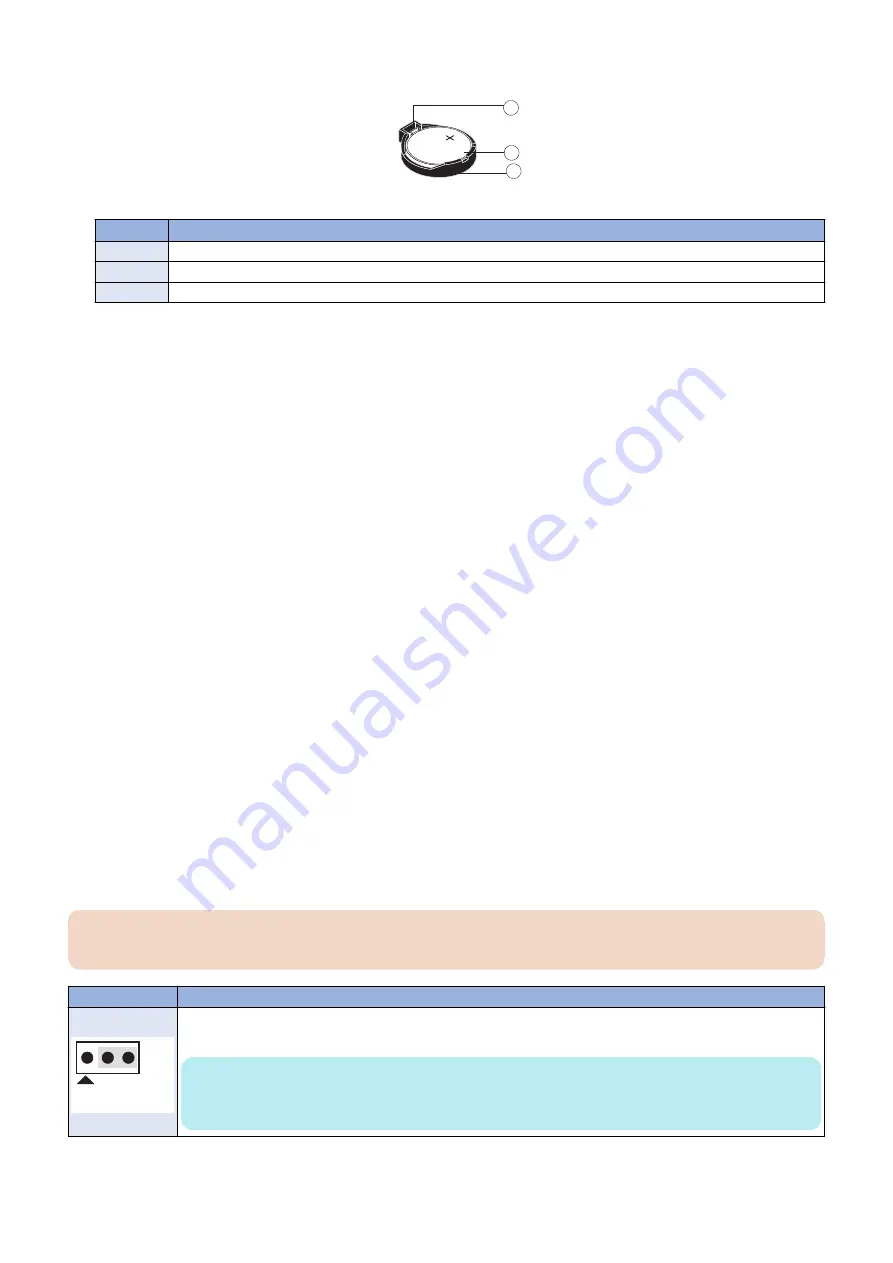
3. Carefully push the clip away from the battery until the socket ejects the battery.
1
2
3
Figure 12: Motherboard battery
No.
Name
1
Clip
2
Battery
3
Socket
4. Slide the battery out of its socket.
5. Wait two minutes to allow the motherboard electrical components to fully discharge.
6. To insert a new battery, slide it into the socket so that the positive (+) side of the battery faces front.
7. Press the battery down into the socket until it snaps into place.
Make sure that the battery is securely installed in the socket.
8. Reassemble the
imagePASS
and verify functionality (see
“Restoring imagePASS functionality after service” on page
).
9. Configure the date and time in Setup (see
“To configure the system date and time” on page 25
To configure the system date and time
1. Access WebTools.
1. On a client computer that is connected to the same network as the
imagePASS
, open a Web browser window.
2. In the URL field of the browser, type the IP address or DNS name of the
imagePASS
, and press Enter. The IP address
is listed under the Network Setup section of the
imagePASS
Configuration page.
2. In WebTools, click the Configure tab.
3. Type the administrator account in User name and the corresponding password in Password, then click Log In.
You can enter “Administrator” or “admin” for the administrator account name.
On the Fiery Server Configuration page,
look for ID in the BIOS Setup section. The alphanumeric characters in the ID field is the default
password.(Print the Configuration page: Press the Fiery logo, then press [Info] > [Print Pages] >
[Configuration].)
“How to obtain the Fiery password” on page 9
) However, the site administrator may have
configured a new password for the
imagePASS
.
4. Select Fiery Server > Regional Settings and specify the current date and time, and click Save.
5. Click Log Out to exit Configure.
■ Motherboard jumpers
IMPORTANT:
Jumper configuration should not be changed.
Jumper
Description
J17
Pin 1
J17 is the Clear CMOS and Password jumper.
Default configuration: jumper cap installed on pins 2 and 3.
NOTE:
Because the jumper cap is very small, it is not necessary—and could introduce an error—to remove the
jumper cap in order to clear the CMOS settings
3. REPLACING PARTS
25
Содержание imagePASS-R1
Страница 6: ...Introduction 1 Introduction 2 Specifications 7 ...
Страница 15: ...Using the imagePASS 2 Using the imagePASS 11 ...
Страница 19: ...REPLACING PARTS 3 Replacing Parts 15 ...
Страница 51: ...INSTALLING SYSTEM SOFTWARE 4 Installing System Software 47 ...
Страница 73: ...TROUBLESHOOTI NG 5 Troubleshooting 69 ...


