


Chapter 7
7-10
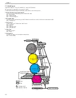
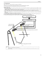
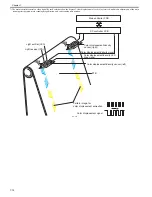
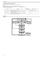
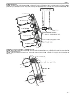
A pattern image for image gradation correction
Image gradation correction pattern is formed on the position away from ETB center to right and left in the following order.
ETB 1st round
1) Pattern image for adjustment of LED light intensity
Y, C, M pattern is printed on the left side only.
This pattern is to adjust the light intensity of the LED for the color displacement/image density sensor (left).
2) Pattern for timing reference
Bk pattern is printed on the same position at right and left.
This pattern is to measure the timing of step 3), 4) and 5).
3) ETB base
The machine measures the ETB base condition of the same position with the halftone patch that is measured at the 2nd round of ETB.
This is to measure the density of halftone patch accurately. The timing is determined with using the pattern printed at step 2).
ETB 2nd round
4) Pattern for density condition
Halftone patch of Bk, Y, C, M is printed on the left side only.
Measures the density condition of each color. The timing is determined with using the pattern printed at step 2).
5) Pattern for turn-on density detection
Halftone patch of Bk, Y, C, M is printed on the right side only.
This is to detect the turn-on density of each color (the printable minimum density). The timing is determined with using the pattern printed at step 2).
F-7-15
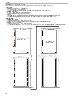
Vertical synchronous
signal position
Vertical synchronous
signal position
1) Pattern image for adjustment
of LED light intensity
2) Pattern for timing reference
3) ETB base
ETB 1st round
ETB 2nd round
4) Pattern for
density condition
5) Pattern for turn-on
density detection
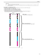
The pattern printed
at ETB 1st round
Содержание imageCLASS MF9170c
Страница 16: ...Chapter 1 Introduction ...
Страница 55: ...Chapter 2 Basic Operation ...
Страница 61: ...Chapter 3 Main Controller ...
Страница 75: ...Chapter 4 Original Exposure System ...
Страница 88: ...Chapter 5 Original Feeding System ...
Страница 105: ...Chapter 6 Laser Exposure ...
Страница 113: ...Chapter 7 Image Formation ...
Страница 150: ...Chapter 8 Pickup and Feed System ...
Страница 184: ...Chapter 9 Fixing System ...
Страница 200: ...Chapter 10 External and Controls ...
Страница 230: ...Chapter 11 Maintenance and Inspection ...
Страница 233: ...Chapter 12 Measurement and Adjustments ...
Страница 237: ...Chapter 13 Correcting Faulty Images ...
Страница 251: ...Chapter 13 13 13 13 3 5 PCBs 13 3 5 1 PCBs 0019 5065 imageCLASS MF9170c imageCLASS MF9150c imageCLASS MF8450c ...
Страница 256: ...Chapter 13 13 18 F 13 19 21 22 28 29 30 31 24 14 15 16 23 26 25 32 27 20 19 18 17 2 13 6 10 33 1 8 4 3 12 11 5 7 9 ...
Страница 260: ...Chapter 14 Error Code ...
Страница 272: ...Chapter 15 Special Management Mode ...
Страница 280: ...Chapter 16 Service Mode ...
Страница 322: ...Chapter 17 Upgrading ...
Страница 327: ...Chapter 17 17 4 3 Click Next F 17 4 4 Select a USB connected device and click Next F 17 5 ...
Страница 328: ...Chapter 17 17 5 5 Click Start F 17 6 6 Click Yes F 17 7 Download will be started F 17 8 ...
Страница 330: ...Chapter 18 Service Tools ...
Страница 334: ...Appendix ...
Страница 349: ......


